Courses by Software
Courses by Semester
Courses by Domain
Tool-focused Courses
Machine learning
POPULAR COURSES
Success Stories
Week 9 - Parametric study on Gate valve.
Introduction The gate valve is the fluid valve that opens by lifting the barrier gate from the path of the fluid flowing thriugh a pipeline. Gate valves require generally very less space and are and can be fitted along the pipe axis and they hardly restict any fluid flow when they are fully opened. The schematic of the…
Athiyaman R
updated on 06 Sep 2021
Introduction
The gate valve is the fluid valve that opens by lifting the barrier gate from the path of the fluid flowing thriugh a pipeline. Gate valves require generally very less space and are and can be fitted along the pipe axis and they hardly restict any fluid flow when they are fully opened. The schematic of the gate valve can be seen below:

Gate valves are generally used to shut off the fluid flow inside a pipe line and also to control the fluid flow. When they are fuly opened they hardly restrict any fluid flow, thus offering very low flow resistance when fully opened. Gate valves are generally used for the pipe of diameters larger that that of 2" to the largest pipes. They are simpler to construct in large sizes. The gate can vibrate if it is in partially open state.
Genewrally in pipelines with high pressure the gate valve opening can be quiet difficult due to the high force exerted on the gate. So trhey are generally connected with a smaller bypass valve to release the pressure and then trhay are operated.
Modeling
The mode for the gate valve can be prepared in any CAD software and thus can be imported in Ansys Space Claim.

The model once imported is checked for any incoming errors such as extra edges and others. Once the errors are repaired the flanges on both the sides of the gate valve are pulled by 800mm to simulate the proper flow while defining the inlet and the outlet for the fluent. It can be seen below:

Further the gate disc is moved by 10mm towards the handwheel and the valve is then parameterised by cling the 'P' button and the group is then created. Volume is then extraced using the volume extract command and the volume is updated in context to update the valume as the parameter changes.

MESHING
Details:
- Element Size: 5.5 mm
- no of Elements: 547178
- no of Nodes: 107029

Setting Up Physics:
First of all the mesh is set up and the solver is defined as below:
Solver Type: Pressure Based Solver
Gravity: -9.81 (in negative z direction)
Solver: Steady State
Model: k-epsilon model (realizable with scalable wall function)
Material: Water
Cell Zone: Fluid(water)
Inlet Boundary Condition : Pressure Inlet (10Pa)
Outlet Boundary Condition: Pressure Outlet
The model will be initialised with standard initialisation and the data will be computed from inlet.

For different gate valve lift values, the output of mass flow rate is as shown in table below:

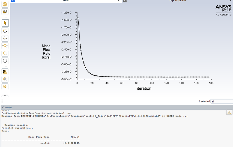
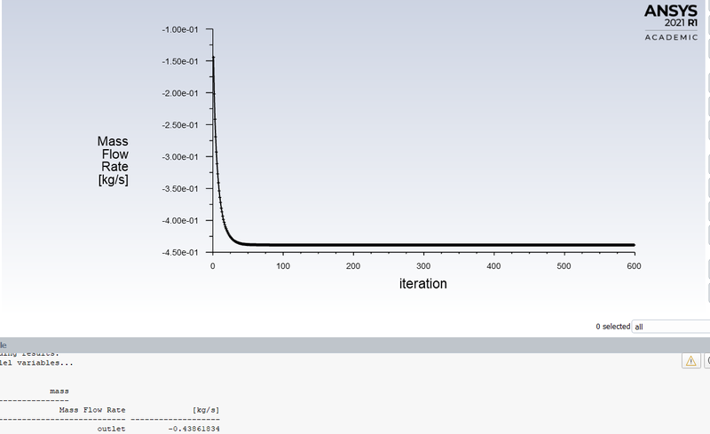
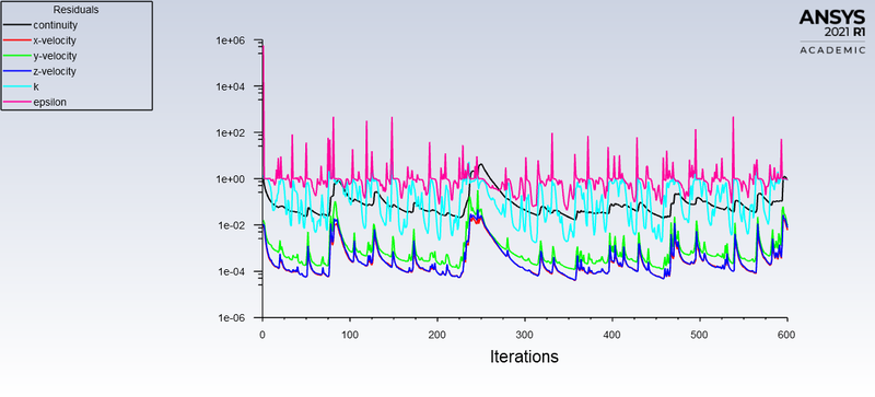
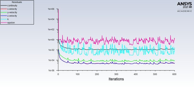
The below graphs are of residuals and of mass flow rate at the outlet respectively. The solution reaches convergence at around 190 iterations.
The mass flow rate at outlet is for the gate rise of 10% is -0.22801 kg/s. Simlilarly till 80% of the gate lift, the values for mass flow rate are displayed in the above table.
Images for only one value of gate rise are shown. All the other values of gate rise are parameterized and the mass flow rate values are obtained directly. This saves computational time.
Flow Factor(Kv):
Flow factor is the flow coefficient in the metric units. It is basically defined as the flow rate in cubic meters per hour for water at the constantr temperature of 16 degree celcius with the pressure drop of 1bar across teh valve.
Flow Coefficient (Cv):
Cv is the flow coefficient in the imperial units. It is basically defined as the flow rate in US Gallons per minute of water at a constant temperature of 60 degree farenheitand a pressure drop of 1 psi across teh vavle. It is used to determine the flow for various conditions and to select the proper valve for the various applications.
The flow coefficient can be defined as :
where,
k= flow coefficient in Kv or Cv
Q= flow rate
Sg = specific gravity (1 for water)
ΔPCv=0.1418⋅(110)12=0.044= Total Pressure Drop
Kv = 0.862 * Cv
RESULTS:
CASE _1: Gate Disc Lift = 10 mm

RESIDUALS:

Mass flow Rate

Velocity Contour:

Cv = 0.044
Kv=0.865 x Cv = 0.865 * 0.044 = 0.038
Kv=0.038
Gate Disc Lift = 20 mm
Residuals:

Mass flow rate:

VELOCITY CONTOURS:

Cv = 0.072
Kv=0.865 x Cv
Kv=0.062
Gate Disc Lift = 30 mm
RESIDUALS:

MASS FLOW RATE:
VELOCITY CONTOURS:

Cv = 0.105
Kv=0.105*0.865
Kv=0.091
Gate Disc Lift = 40 mm
RESIDUALS:

Mass flow rate:
Velocity contour:

Cv = 0.138
Cv=0.524⋅(110)12=0.165
Kv=0.119
Gate Disc Lift = 50 mm:
Residuals:

Mass flow rate:

Velocity contour:

Cv = 0.165
Cv=0.693⋅(110)12=0.219
Kv=0.143
Gate Disc Lift = 60 mm
Residuals:
Mass flow rate:

Velocity contour: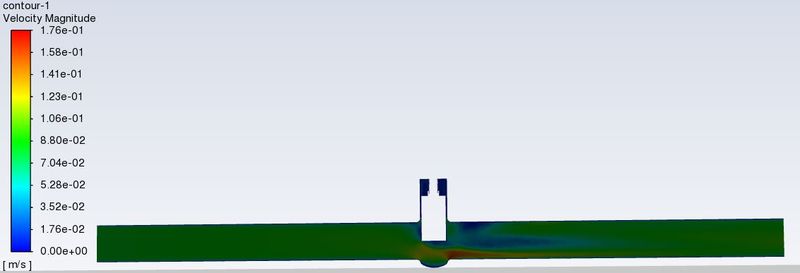
Cv = 0.182
Kv=0.157
Gate Disc Lift = 70 mm:
Residuals:
Mass flow rate:

Velocity contours:

Cv = 0.219
Kv=0.219*0.865
Kv = 0.189
Gate Disc Lift = 80 mm:
Residuals:

Mass flow rate:

velocity contours:

Cv = 0.244
Kv=0.244*0.865
kv = 0.211
TABULATION:
| Case | Mass flow rate | Gate disc lift (mm) | Flow coefficient | Flow factor |
| 1 | 0.1418 | 10 | 0.044 | 0.038 |
| 2 | 0.22801 | 20 | 0.072 | 0.062 |
| 3 | 0.34324 | 30 | 0.105 | 0.091 |
| 4 | 0.43862 | 40 | 0.138 | 0.119 |
| 5 | 0.52456 | 50 | 0.165 | 0.143 |
| 6 | 0.57718 | 60 | 0.182 | 0.157 |
| 7 | 0.69389 | 70 | 0.219 | 0.189 |
| 8 | 0.77307 | 80 | 0.244 | 0.211 |
From above table we can observe that
As the opening of the Gate Valve or Lift of the Gate Disc increases, Mass Flow Rate increases. With Increases in Mass Flow Rate, there is an increment in Flow Coefficient. Also Increases in Flow Factor is observes at each Design Point from 10 to 80 mm Lift. So, Graph of Mass Flow Rate, Flow Coefficient and Flow Factor go linearly with Gate Disc Opening.
CONCLUSION:
- The mass flow rate is increasing with the increment in gate valve lift.
- Similarly, since the flow coefficient is proportional to the mass flow rate as it can be seen from the formulae, the values of the flow coefficient increase with respect to the increase in gate valve lift.
- The velocity contour also shows that the flow velocity is more when the opening displacement is more.
- When the valve is fully open, Mass Flow rate and Flow Coefficient and Flow Factor becomes maximum. Thus, parametric study helps to analyze the different positions of valve opening and gives the benefit to get easily and quick results.
Leave a comment
Thanks for choosing to leave a comment. Please keep in mind that all the comments are moderated as per our comment policy, and your email will not be published for privacy reasons. Please leave a personal & meaningful conversation.
Other comments...
Be the first to add a comment
Read more Projects by Athiyaman R (16)
Week 10 - Simulating Combustion of Natural Gas.
Theory of Combustion: It is a high-temperature exothermic reaction (redox) between a fuel (reductant ) and an oxidant or the oxidizer to release a large amount of chemically bound energy. A flame is a characteristic indicator of the combustion reaction.lt is a sequence of elementary radical reactions. Solid fuels undergo…
23 Sep 2021 08:31 AM IST
Week 9 - Parametric study on Gate valve.
Introduction The gate valve is the fluid valve that opens by lifting the barrier gate from the path of the fluid flowing thriugh a pipeline. Gate valves require generally very less space and are and can be fitted along the pipe axis and they hardly restict any fluid flow when they are fully opened. The schematic of the…
06 Sep 2021 05:19 AM IST
Week 8 - Simulating Cyclone separator with Discrete Phase Modelling
Empirical models for Cyclone Separator Efficiency: Iozia and Leith Model: Iozia and Leith logistic Model is a modified version of Barth (1956) model which is developed based on force balance. The model assumes that a particle carried by the vortex endures the influence of two forces: a centrifugal force Z, and flow resistance,…
26 Aug 2021 01:44 PM IST
Week 6 - CHT Analysis on a Graphics card
Conjugate Heat Transfer (CHT) Conjugate heat transfer is defined as the heat transfer between two domains by exchange of thermal energy. For a system the thermal energy available is defined by its temperature and the movement of thermal energy is defined by its heat flux through the outer walls. Heat transfer in…
02 Jul 2021 05:34 PM IST
Related Courses

Skill-Lync offers industry relevant advanced engineering courses for engineering students by partnering with industry experts.
Our Company
4th Floor, BLOCK-B, Velachery - Tambaram Main Rd, Ram Nagar South, Madipakkam, Chennai, Tamil Nadu 600042.
Top Individual Courses
Top PG Programs
Skill-Lync Plus
Trending Blogs
© 2025 Skill-Lync Inc. All Rights Reserved.


