Week 8 - Challenge 4 - Coin Holder Design
AIM:-
To create a Door arm rest from the given A class surface by adding athickness of 2.5 mm to it and also carry out the ceating the toolingaxis and performing the draft analysis of the component.
TOOLING AXIS:-
The purpose of toolin axis is basically the direction that the mold opens. The mold is built in two separate pieces, these are core and cavity. The Core and cavity moves along the Tooling Direction. There are different methods to find out the tooling direction. Here we are using bisecting method to find out tooling direction. We can use any method. but our main aim is to reduce the cost of manufacturing by reducing the complicity in manufacturing the component.
PROCEDURE:-
Here i am using bisect method to find out the tooling axis for fan cover. then we perform the draft analysis on the fan cover.
CREATING THE TOOLING AXIS USING BISECT METHOD:-
- The first thing to do is finding out the possible tooling direction by visually checking the part. Rotate the part in all direction and find out the possible direction for tooling axis. Here in this case viewing from Z direction we can clear the face in tooling.
- Then we create a point on the surface of the part, we can create the point anywhere on the surface.
- most of the cases we create the point in holes and pocket of the part.because the holes and pockets is to create a problems when we do the draft analysis.so we create a point in mid of the hole. to create a line on this point along z direction.
- in this case the tooling axis can clear the all faces of the coin holder.
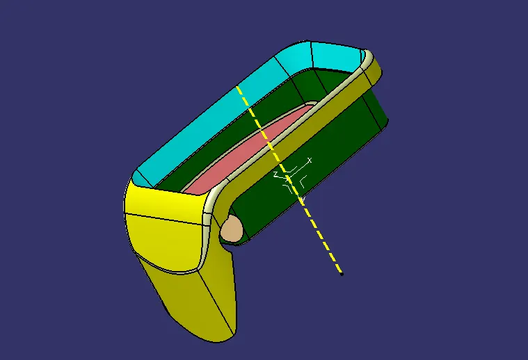
and then publish the tooling axis.
Class B surface creation:
for the class b surface we need to extract the all surfaces of the class a surface. for the class b we divided into base top walls,side wlls, and outer flange.
for the base all the surfaces for the inclined portion of the base plate.Then these surfaces are first untrimmed to get the intersection for surfaces so that a replica can be created.If the surfaces are not intersected, then extrapolate by point continuity propagation is used to make these surfaces have an intersection between them Lastly, the surface trim is used to get the replica for the inclined surface. Now, the thickness of the final component is 2.5mm so this obtained surface is offset below by 2.5mm.
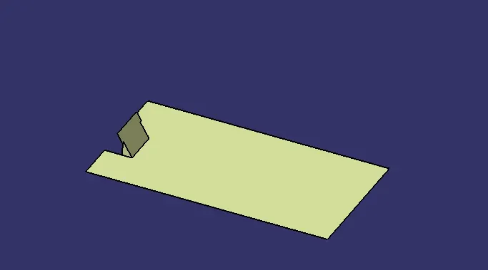
then create the walls for that extract the class a surface. If the surfaces are not intersected, then extrapolate by point continuity propagation is used to make these surfaces have an intersection between them Lastly, the surface trim is used to get the replica for the inclined surface. Now, the thickness of the final component is 2.5mm so this obtained surface is offset below by 2.5mm.
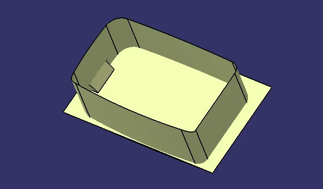
then create the top walls for that extract the class a surface. If the surfaces are not intersected, then extrapolate by point continuity propagation is used to make these surfaces have an intersection between them Lastly, the surface trim is used to get the replica for the inclined surface. Now, the thickness of the final component is 2.5mm so this obtained surface is offset below by 2.5mm.
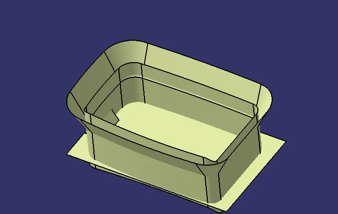
then create the outer flange for that extract the class a surface. If the surfaces are not intersected, then extrapolate by point continuity propagation is used to make these surfaces have an intersection between them Lastly, the surface trim is used to get the replica for the inclined surface. Now, the thickness of the final component is 2.5mm so this obtained surface is offset below by 2.5mm.
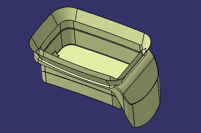
and then give the fillets to the all surfaces and trim these all surfaces to form a class b surface.
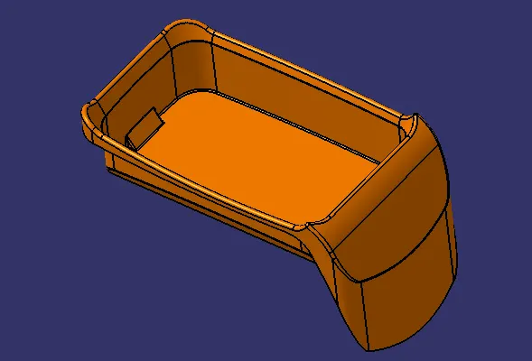
CLASS C SURFACE CREATION:
The C class surface will be created using the sweep command and for that, the Boundary lines are obtained from the A-class surface.ThE curve part is then smooth by some value for ease in sweeping. Then, all boundary lines are sweep with draft direction since all the surfaces must have a draft angle of 3 degrees. Also, the tooling axis is used as the direction of the sweep.
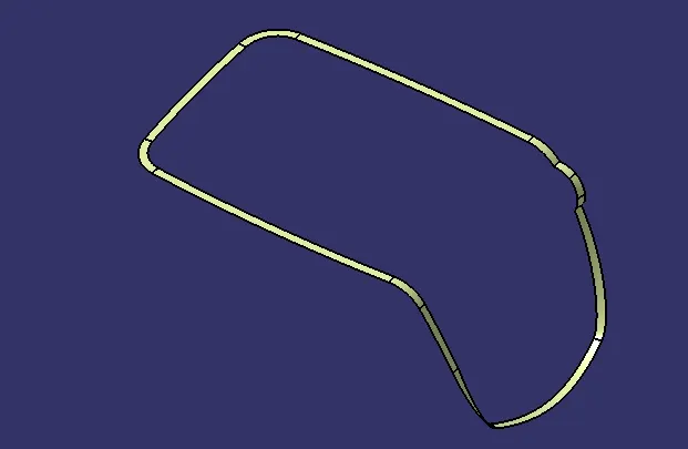
Next, the swept surfaces are joined with the A-class to form a complete A and C surface.(note merging distance is kept at 0.003mm to avoid any gaps)
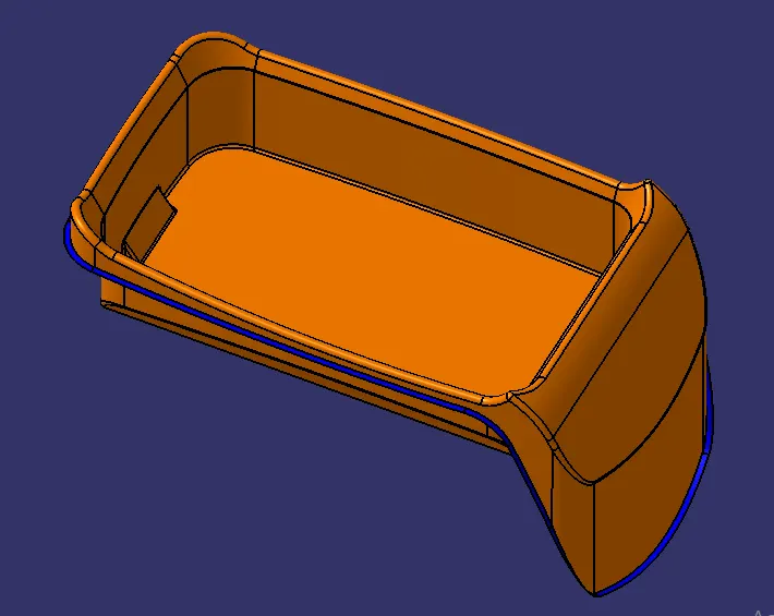
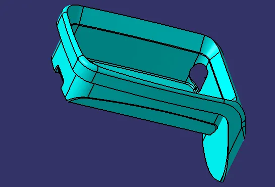
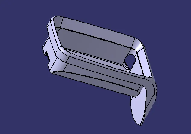
Lastly, the A and C is trimmed with the B surface to get the final component. This obtained surface is then thickened in part design.
surface body
part body
DRAFT ANALYSIS:-
The Draft Analysis command enables to detect if the part you drafted will be easily removed from the core and cavity. This type of analysis is performed based on color ranges identifying zones on the analyzed element where the deviation from the draft direction at any point, corresponds to specified values.In Draft Analysis, the Class C surface side walls are checked for draft. A minimum 3 degrees draft is expected on the component to make it manufacturable without any damage to the product. and it is eaisily withdrawl from the core and cavity after manfacturing.the draft analysis gave a report whether the tooling axis can clear the all faces of the parts.some times it cant cler the all faces due to complexity of the part. so side tooling axis are used to clear that face.for that a side cores are used to manfacturing the compopnent.
PROCEDURE:-
- To perform the draft analysis the view parameters are first set to material mode.
- Then go to Insert >>analysis>>feature draft analysis.the fallowing window will be appread
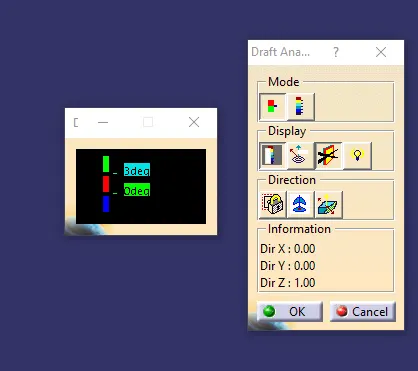
- First, select the axis system and drag the axis system to the tooling axis and lock the orientation. This axis system defines the draft direction according to the tooling axis.
- Switch on the color scale and set the draft value 3° using colour scale. and it will be displayed in green color. Any draft angle below 3 degrees will be shown in red color.
- Here, the compass direction is rotated to have the positive direction in the maximum portion of the part. Then the compass is locked in the orientation and a new tooling axis is created using the compass as the direction.
- Now select the running point tool to measure the draft angle at the various locations and then if all surfaces pass the draft analysis switch on the light effect that will show the component in green color if the component has the required draft angle.
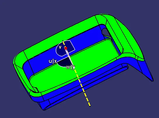
RESULT:
The Class b and c surafces are created from the class and trimmed these surfaces to form a part bodt body having 2.5 mm thick. and the draft analysis also done for the final component.