Week 8:- 3D Finishing Challenge 2
AIM:
- Perform 3D finish for all units of Assembly design.
- Create Roug
3D-FINISHING:
3d Finish is a process where the design is being completely finish and to be ready for final simulation and 2d detailing.
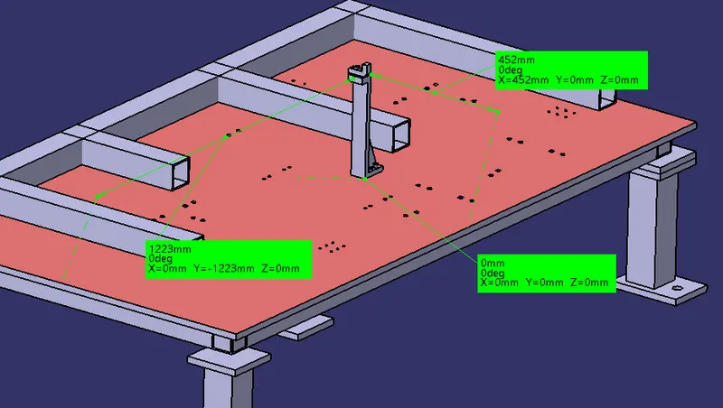
- While finishing the design the nominality is checked which ensures the easy assembly of all the units.
- The hole concentricity and holes sizes are checked which ensures the assembly of different parts.
- The gaps between the different units are checked to ensure the proper individual working of different units.
- Design the rough locators, which helps to loading a panel in correction orientation.
- Design the pneumatic lay outing for pneumatic connection.
- Gun study is major and most important part in 3d finishing.
- Selection of sensors, Solenoid valves as per the requirement and implementing in design.
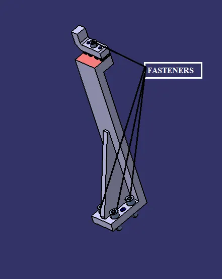
- Fasteners are implemented as per the hole size and the standard colour codes as per the customer requirement are applied to differentiate the type of hole whether its dowel hole, Threaded hole or clearance hole.
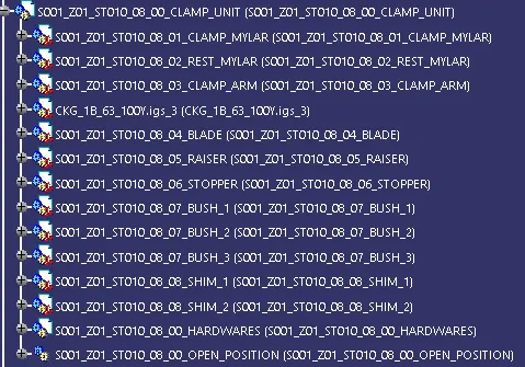
- Renaming of the assembly and the part is done to give every part a different identity so everyone can identify in which assembly this part is going to be fit.
- After doing all these things the model is sent for simulation and 2d detailing.
Points Need to Be Taken Care of While Finishing the Design:
The following are the points taken into consideration while finishing the design.
- Hole Concentricity and Hole Sizes:
All part holes concentricity and hole sizes are checked for easy assembly while finishing the parts.
- Machining Area:
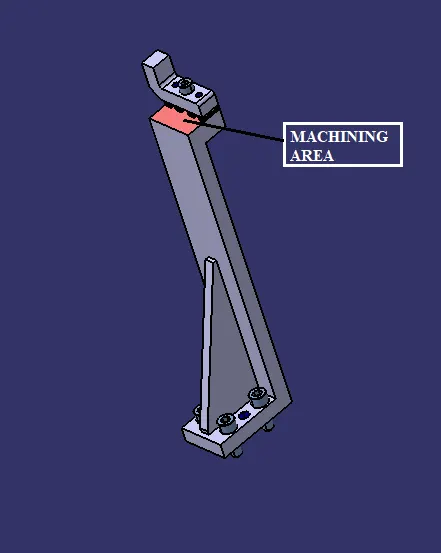
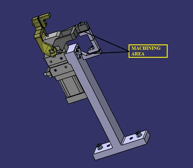
The machining area in every part should be defined and the machining area should be highlighted by using standard colour code. Machining is to be done on parts to properly Mount with mating parts. Machining only on desired faces reduces cost and save time. And also Machining increases accuracy of dimension. So before going to simulation or detailing machining area should be defined.
- Nominality:
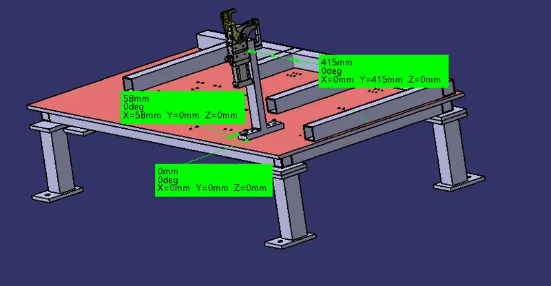
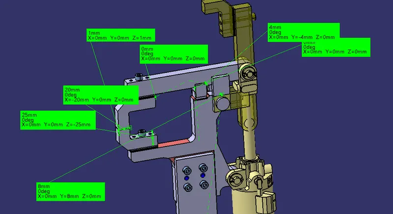
All unit’s dimension should be maintained nominal to facilitate easy assembly of the unit.
- Holes Colouring Standard:
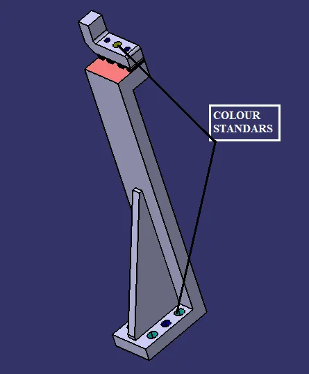
In a 3D finish hole colouring should be done because it helps to identify what type of hole it is. It depends on customer standards. Customer specific colour like:
Dowel hole should be given blue colour.
Threaded hole should be coloured with yellow.
Counter bore, open hole should be given cyan blue colour.
- Pneumatic Lay outing:
Pneumatic lay outing is collection of different pneumatic pipes which work as a inlet to the pneumatic cylinder. It should be done properly for proper functioning of the units.
- Gaps Checking:
The gaps between the different units are checked to ensure the proper individual working of different units.
- Fasteners Implementation:
Fast should be implemented in all the units as per the requirement and load on the part.
- Avoiding Clash Between Different Parts:
Proper gap should be maintained between units to avoid the clashes between the different units.
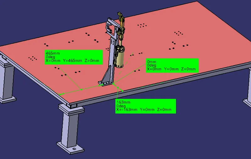
- Mylar Splitting as Per Panel Profile:
Mylar splitting as for panel profile should be confirmed while finishing the design.
- Proper Renaming of Parts or Assemblies as Per the Standards:
Proper renaming of parts and assembly should be done while finishing the design and hence we can identify each and every part easily with Unique Identification.
ROUGH LOCATORS:
- A rough locator is a part designed to guide the panel, to locate the car panel on to the pins accordingly. A rough locator can be of standard part or a make part.
- Rough locators also work as Poka yoke. Poka yoke is a Japanese concept used for mistake proofing.
- Rough locators are also used to help to locate the work pieces in the automation process. Locating refers to the desired location where you want the workpiece to be when it is getting worked on either by a person or a team or a robot.
- The accuracy of the locating components directly affects the consistency and how the final product will come out. This is why these components are essential to our setup.
- It can be also called as fool proofing method. Because without rough locator the part cannot be loaded in correct position.
- The rough locators are set accordingly to the angle of the respective panel and hence the part can be loaded in a defined direction and orientation only.
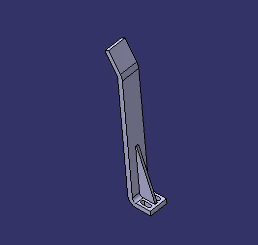
FIG:rough locator
Points Needed to Consider While Designing A Rough Locator:
The following are the points needed to be considered while designing the rough locator.
- Rough locator should be placed at the edges of the car panel, which it has to guide.
- Applicator has to be placed in the same angle of the car part edge with a minimum distance of 2-5 mm from the edge of the car part.
- Prof locator should guide the panel in pin arresting direction.
- Rough locator should start guiding the panel before 10 to 15mm to the start of the pin engagement.
- Applicator should be designed with entry angle for the car panel. Generally, it ranges between 30-45 degree.
- Rough locator should be designed with two slots to mount the easy adjustment.
- The slot should be in the direction of car part guiding.
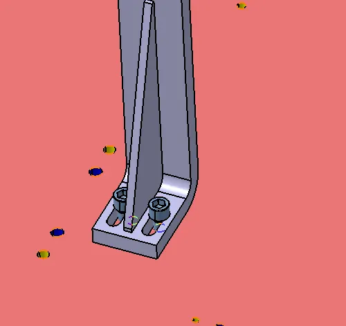
FIG: slot given to rough locator to adjust the position
Positioning of rough Locators on the Base Plate:
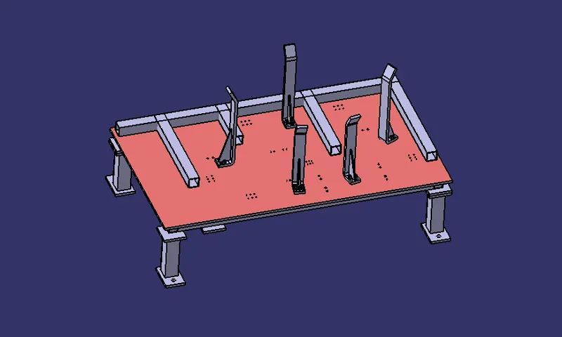
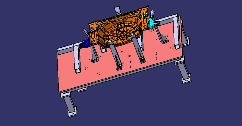
GUN STUDY:
Welding is predominantly used in automobile industries and requirements for fixtures that ease the welding process is a continuous development task in any industry. Car Body-In-White (BIW) is a complicated steel-structure including 300~500 sheets with complex shape and are assembled by means of welding in a high rhythm through 55~75 robotic work-stations. The foremost step taken before starting the design of welding fixture is to arrive at the spot weld locations. The location and orientation of other critical units of the fixture including clamps, locators etc., are decided based on the weld spot distribution. The weld spots for Front door inner panel Side bracket assembly are located as shown in Table 1 with respect to the body line of car. It includes the study of the weld gun (A portable device for semiautomatic welding of parts of various articles) which is going to be used for the operation depending on the size of the part, Thickness of the part etc. It includes the study of the weld matrix & the weld point positions. There are two types in weld point one is geo weld points which ensures the geometry of the assembly & second is the Re spot weld points which adds strength to the already welded part.
The device used to make spot welding on the panel is called Gun. The Gun may differ depending upon the application. Fixtures will be designed by considering the weld spots on the panel. After designing the Fixture, the CAD file of the gun be placed on the weld spots to check whether the Gun is clearances with the Fixture. After adjusting the Fixtures, the coordinates of the welds be taken for further operations of Weld Gun.
Points needed to consider during gun study:
Weld gun study is very time-consuming process, the entire welding cycle time study depends on the no. of spots & weld gun study.
Following are the points need to consider during gun study.
- The axis of weld spot along welding direction must be normal to the weld surface.
- The no. of weld spots for the panel, the time required to spot each weld & the total time required to complete all weld spots.
- If we have one or more device models & we want to program, the behaviour of each model in the work cell can be simulated over time. Instructions for each device are coded by giving sequences. The sequence defines the motion, manipulation & action of the devices. Based on the distance of each tag point from home position, motion type, speed & acceleration one can obtain cycle time for each device assigned with sequences. This way robot cycle time is precisely calculated.
- After sequencing all the devices, a simulation is run with “collision check” ON & made sure that the welding operation is collision free.
FIXTURE ASSEMBLY:
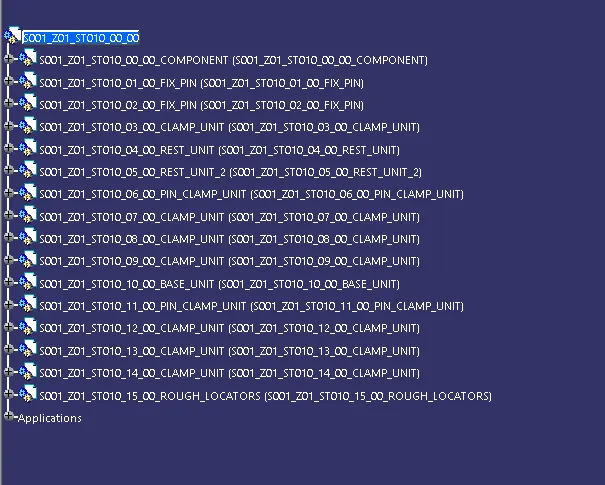
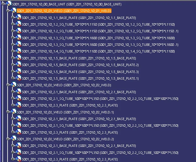
Renaming and structuring of the design tree:
Renaming of the design tree is done. and structuring design tree in way that its simple to identify the units. some units use multiple time those are easy to identify by its name.
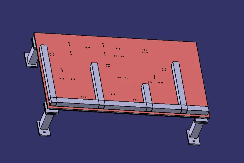
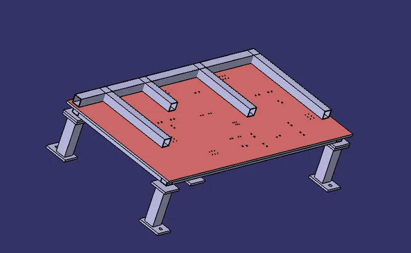
BASE UNIT:
INTRODUCTION & THEORY -
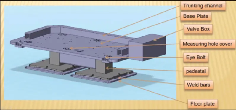
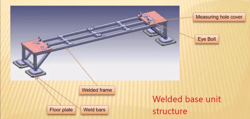
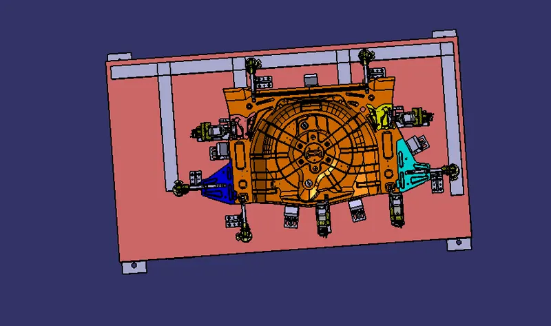
- A base unit is a unit on which all other units of the tool and other necessary parts of the tools like trunking channel , valvebox , eyebolt etc are assembled .
- Holes will be drilled on the base plate to mount all the necessary units of the tool on it .
- Base unit is an important unit in fixture assembly as it mounts all the units on it , so the base unit should be designed such that it can take up the load and absorb all the vibrations during the welding operation .
Parts of base unit -
a) Base plate -
- A base plate is a machined plate with thickness of 20 - 40 mm thickness .
- A base plate has holes drilled on it so that all the units can be mounted on it .
b) Pedestal -
- Pedestal is a part which connects base plate to the floor plate .
- It is a standard part in general and in some cases it can be welded frame integrated with base plate.
- A standard pedestal can be of different height and size.
- Depending on size of base plate , the number of pedestal varies for load distribution .
c) Trunking channel -
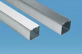
- It is a duct which accomodates all the electrical and pneumatic hoses and wires for the unit of tool .
- Trunking channel is available in different thickness and different sizes .
d) Valve box -
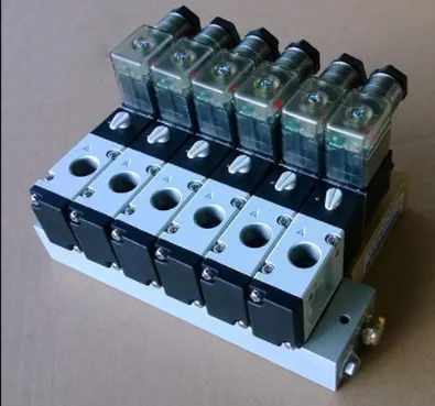
- It is a standard part which contains all the valves for the units.
- It supplies air to the pneumatic cylinders in the assembly .
- Valve box consist of solenoid valve which is used for air supply.
e) Eye bolt -
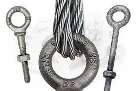
- Eyebolt is a part which is attached to the base unit , it is used for transportatiion purpose of tool.
- Lifting hooks will be used to lift the base unit or the entire tool .
- Forklift holes will also be provided in case of transportation purpose.
f) Floor plate -
- Floor plate also known as foundation plate is grounted to the floor with fixed bolt on the ground .
- A clearance of 10mm is provided between pedestal and floor plate .
- weld bars are used to weld position permanently after levelling is done .
Points that are needed to be taken into consideration while designing base unit -
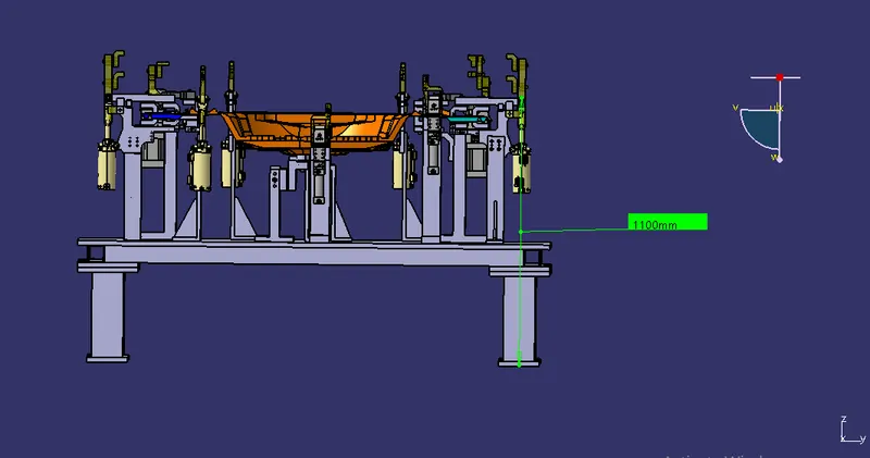
a) Working height - the working height of the base unit is an important consideration . the working height depends upon the type of welding operation like manual welding or robotic welding . for manual welding , the overall height of total tool should be 850-1100 mm in general . the working height also vary from country to country .
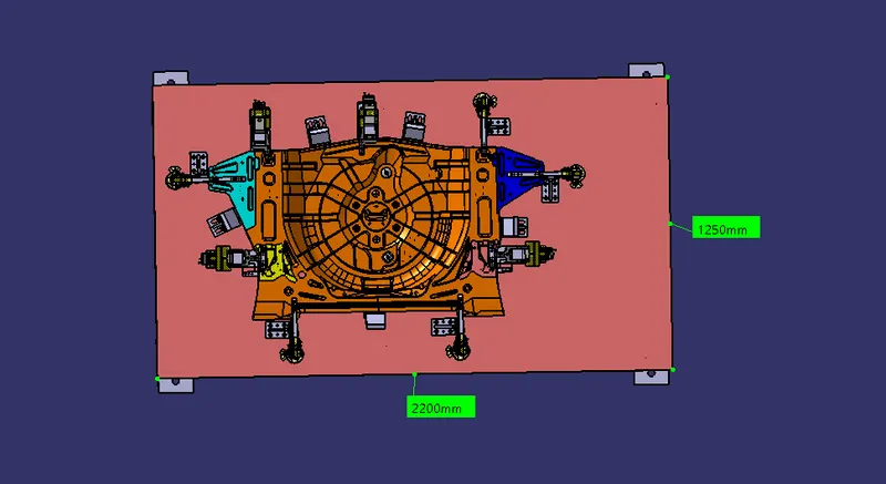
b) The dimension and the specification of base plate is also an important factor .below is the fundamentals given for base plate.
Fundamentals Of a Base Plate Design:
The fundamentals of a base plate design are:
- As designer it is important to know how big base plate or bigger base welded structure will be handled during the fabrication & handling process. Special care needs to take care of flatness if the base size is very long.
- A base plate size should cover all the units with its outer periphery including opening.
- A base plate is preferred to be designed with respect to BCS coordinates.
- A base plate should be drilled with datum holes / measuring holes in line with a pitch of 1000 mm in general.
- Number of datum holes is depends on the size of the base plate.
- Datum holes should be drilled at nominal values of coordinates, & in terms of 50 x 100. (In general) ex. X=100, Y 600, Z-250.
- Datum holes should be drilled with dia 100 mm away from other units.
- Datum holes should be covered with cover plates.
- Depending upon the weight, eye bolt size is selected for lifting holes on base plate Generally, 4 eye bolt provision is made You also need to select the location of eye bolt considering the rope/ belts used while shifting the structure or complete fixture are not damaging any units (rest, clamp or location units) nearby.
- Depending upon the component size & weight of the total units you can decide whether you need a fabricated base or just plate. Mostly fabricated bases are used made of square or rectangular tube with the plate.
- Most of the OEM makes 4 dowel holes at 4 corners & put small aluminum plate marking X Y&Z coordinates of dowel holes. If the base length is too long few OEM' s follow the methodology of having holes at 500 mm distance.
- The best unit of the fixture must be strong enough so that deflection of the fixture is as minimum as possible. This deflection of a fixture is called because of forces of welding, clamping of the work piece.
- The base unit of the fixture should have the mass to prevent vibration & chatter.
- The base unit may be built from simple sections so that other units may be fastened with screw or Welded necessary. Those parts of the fixture that remain permanently with the fixture may be welded. Those parts that need frequent changing may be held with screws .
- The base unit should be parallel to the floor to adjust this there should be provision of the height adjusting mechanism.
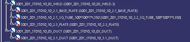
Renaming of parts list in the base unit:
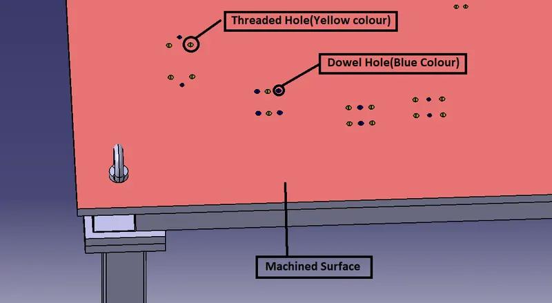
Colour Coding given to the holes on the base plate:
- Threaded hole and dowel holes making nominal and colour-coding are done so easy to distinguish holes.
- Threaded hole (Yellow), clearance hole (Sky blue), Dowel Hole(Blue), Machining surface(orange).
REST UNIT:
Rest unit is unit designed to support car panel using Mylar/ NC block/ rest component is rested only, no upper clamp or force applied there. It is the simplest unit to design because it has fewer parts to design & the purpose is only resting of the car panel.
Because of the simplicity the rest unit is combined with other unit to reduce the cost of the overall project.
It can be combined with clamp unit to clamp as well as to rest the car panel. It can be combined with locating unit to locate as well as to rest the car panel. Also locating, clamping & Test unit can be combined together in one unit to reduce cost.
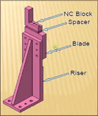
There is no cylinder attached to it. It has rest Mylar, blade and riser & below is different parts of rest unit. Rest unit is also divided into simple support unit, multiple support units & retractable support unit.
NC block/Mylar:
- NC blocks or popularly also known as Mylar is the ones which hold the panel.
- It prevents the panel from deforming while welding.
- They always come in pairs.
- Top Mylar is known as clamping Mylar and bottom Mylar is known as resting Mylar.
Few points to remember about Mylar:
- Generally Mylar clamping block clamp cross section (the area which in contact panel) is considered as 20mmx20mm.
- Most of the OEM's /Tier 1 prefer Mylar to have 5mm allowance material for machining. Most of Mylar are CNC machined if it is clamping 3D profile.
- Depending on the angle of cross section, Mylar will be having shimming either in one direction or in 2 directions. General Thumb rule is if the section is inclined more than 15 deg or clamping surface is 3D profile then 2 direction shimming is provided. The reason being simple mathematics. Equation of inclined line/ plane will be having 2 parameters to controls and we control with shimming in 2 directions. Less than 15 deg does not mean that there are not 2 parameters. These are their but they are neglected if angle is less than 15 deg.
Shim:
- Shims are washers or thin strips of material used to align parts, make them fit or reduce wear.
- Shims are designed to fit in between blocks and fixtures to provide support or reach a dimension required in the assembly.
- Typically designed in a U shape matter so that they can fit between mounting screws. This shape helps to make them easy to install and remove or replace.
- Designers will use shims individually or as packs of 5, 6, or 7 pieces. Thicknesses range from 0.25mm to 2mm.
- Many assemblies require a tolerance to be hit in relation to a length or height; shims allow designers to hit these tolerances. They can be stacked between NAAMS NC blocks, L blocks, or pin retainers.
Riser:
- Riser is a structure generally used to mount the toggle clamp and rest, clamp Mylar and location pin and to give height to the assembly.
- It is not necessary to have one riser where all the parts of clamp or rest or location units are mounted.
- Risers can either be a standard part or make part.
Blade:
- Blade is a plate which is attached to the riser and other components like cylinder, arm etc are mounted on it.
- It can either be a standard part or a make part
Marking of Machining area:
Colouring Standards:
Fasteners Implementation:
Checking the nominality of the UNIT:
Proper Renaming of Parts:
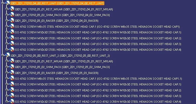
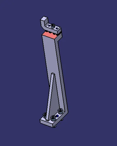
FIG:REST UNIT
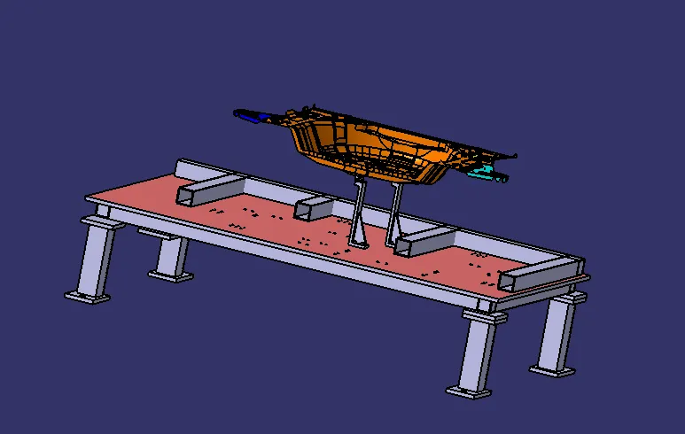
FIG:REST UNIT WITH BASE UNIT AND COMPONENT
PIN UNIT:
Fundamentals of pin unit design:
It is necessary to locate car panel with two pins . one pin to restrict 4 way motion (4 translational ) and one pin to restrict 2 way motion (2 rotational ) .
- Pin should engage 3-5 mm from car panel entry surface .
- All pins should be accomodated with 2 way adjustable shims irrespective of direction of aresting .
- Round pin should be used in arresting 4 way in car panel if the hole is round .
- Round pin should be used in arresting 2 way in car panel if the hole is slot .
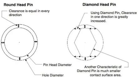
- Diamond pin should be used in arresting 4 way in car panel if the hole is slot .
- Diamond pin should be used in arresting 2 way in car panel if the hole is round .
- The axis of the car panel hole and the axis of the pin should be same (in general ) .
- The pin tolerance for geo pin will be -0.15 mm and for respot pin will be -0.28 mm
MATERIALS USED:
In general, the materials used for pins, pin retainers, shims, shim block, blades & risers are:
- Pin: C45, EN31, SAE 8620 Steel,
- Pin retainer : Steel / ASTM A-36, SS type 303 or 304,
- Shims/spacer: S.A.E. 1010 CRS FULL HARD, COLD ROLLED STRIP STEEL S.A.E. 1010 FULL HARD, S.A.E. 1020 HRS, etc.
- Shim block : STEEL ASTM A-36, NM Stainless, STEEL ASTM A-36, SS type 303 or 304,
- Blade : STEEL ASTM A-36,
- Riser : STEEL ASTM A-36.
SURFACE FINISH:
In general, the hardness of the materials for pins, pin retainers, shims, shim block, blades & risers are:
- Pin: Chrome plating, Zinc coating, Pins with TiN codes shall have 1 to 2 microns of nitride added to
- Pin retainer: BLACK OXIDE FINISH, No black oxide finish for "SS TYPE" components (SURFACES TO BE FLAT, PARALLEL &
PERPENDICULAR TO O WITHIN 0.015 T.I.R).
- Shims/spacer: BLACK OXIDE FINISH (SURFACES TO BE FLAT AND PARALLEL TO WITHIN 0.015 mm T.I.R).
- Riser: SURFACES TO BE FLAT, PARALLEL & PERPENDICULAR TO WITHIN 0.015 T.I.R.
PIN TOLERANCE:
The pin tolerance for a geo pin will be of closer tolerance i.e -0.15mm & for respot, the pin is -0.28mm.
PURPOSE OF PIN UNIT:
- As by the 3-2-1 locating principle, the introduction of two pins helps to arrest the 6 degrees of freedom (4 axial & 2 radial movements) whereas the other 6 degrees of freedom are arrested by introducing a minimum of three supports.
- Typically, the locating pins are used to locate a body part in a position sufficiently accurate to execute a welding process.
- The body part is constrained by a set of appropriately locating pin so total constraint by locating pin should be fully constrained at all times to prevent any movement.
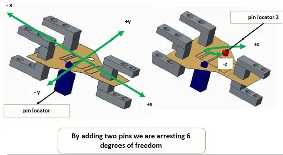
There are two types of pin units -
1)Fixed pin unit -
Fixed pin unit is a unit designed to locate the car panel using pins .
2)Retractable pin unit -
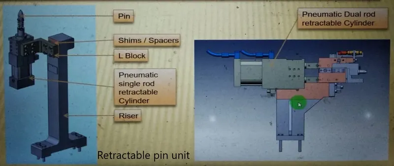
A retractable pin unit is designed to locate the car panel using pins , but the entire pin package is mounted in the retractable cylinder . the cylinder will move the unit up and down .
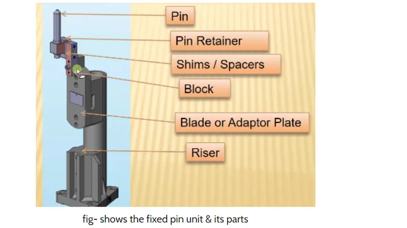
FORMULA & CALCULATION:
Formula to calculate the length of the screw,
Length of the screw = [1.5 X (std. hole size)] + {distance between the surface of the part to the first surface of the other part
Length calculation for the length of the screw.
- To fix the pin retainer & the shim block using standard screws we need to find the length of the screw using the above-mentioned formula.
- The highlighted surfaces shown in the figure are the {distance between the surface of the part to the first surface of the other part}
- Since the given tap holes are M8 & the distance is 25mm as shown in the figure then,
- Length of the screw = [1.5 X (std. hole size)] + {distance between the surface of the part to the first surface of the other part} Length of the screw = [1.5 X 8] + 25 = 37 = 40mm Allen cap screw
- Then the standard size of the screw should be 40mm for connecting the pin retainer & the shim blocks for this example.
1 . Pin
- It locates the car panel . it can either be a make part or a standard part .
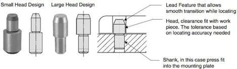
- A pin should have a grinding surface on shaft with fits onto which the pin retainer is fixed .
- The mounting surface of pin should be fine machined surface .
- It should have step machine surface to lock rotation which matches with pin retainer .
- The mounting surface of pin retainer to the block should be machined surface .
- All machined planes should be perpendicular to the axis of shaft .
- Pin must have fastening provision like tapped hole from bottom or a V groove from side .
- A pin must be hardened ( heat treatment ) (55 to 60 HRC) and black oxide finished in general .
- Material - Hardened material like C45 , 16MNCR5 , 20MNCR5 , EN31 etc .
- Surface finish - black oxide , Zinc coating , Chrome plating .
Typically, locating pins are used for controlled, fine tolerance positioning of a, For example, a pallet that is moved along one axis, where the drive mechanism is not accurate and stable enough to place it in a position sufficiently accurate to execute a particular process, the use of locating pins may be the best solution.
The Diamond Shape is a critical feature that helps with machining inaccuracies and smoother locating When two round headpins are installed onto one plate, the distance between two mounting holes must be extremely precise and even then, the workpiece will not be placed on the base as easily as it would with the use of a diamond shape pin.
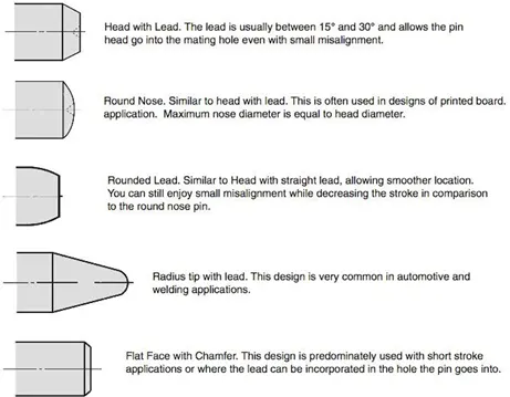
There are several styles of Pin Head They serve different purposes and can be utilized in a variety of applications.
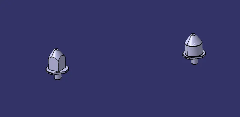
2 . Pin retainer
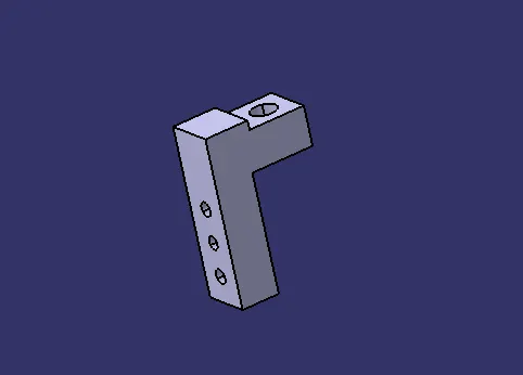
- It is a part which holds the pin in position , it can either be a make or a standard part .
- It should have a hole with a fit onto which pin is fixed .
- The pin mounting surface should be fine machined .
- It should have a step to lock rotation of pin .
- The mounting surface of pin retainer to block should be machined surface .
- The pin retainer will be fixed to block or a L block to riser with 2 dowel holes (pins) and atleast one screw hole to maintain tolerance .
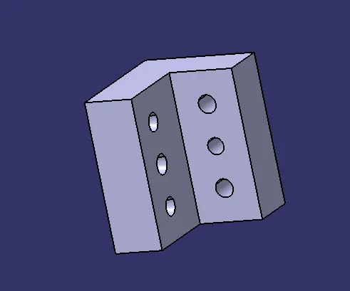
3 . Blocks/ L blocks
- These parts are used to accomodate the shimming direction as per fundamental in general, also in some cases used for other design feasibility
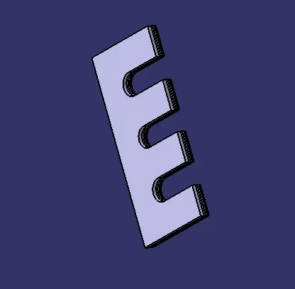
4 . Shims/ spacer
- It is a standard part in general , which are used for adjustment of locator ( NC block and Pin retainer ) for obtaining the desired value for precise working of unit wrt car part .
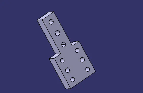
5. Blade
- A blade is part like a plate, which connects the parts on a unit to an In general, the blade can be either a make part or a standard part.
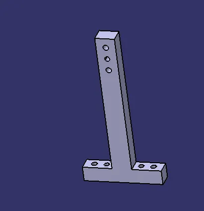
6. Riser
- It is a part on which all the parts of a unit are mounted & is mounted on the base plate of a tool.
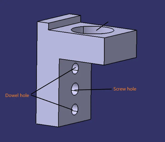
7. Dowel holes & machined surface-
- All make parts which are to be assembled should be designed with 2 dowel holes & at least of 1 to 6 threaded/ free hole(depends on size) 7 to be finely machined for the mounting surface with 3 to 5 mm step machining.
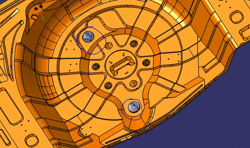
Marking of Machining area:
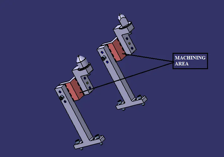
Colouring Standards:
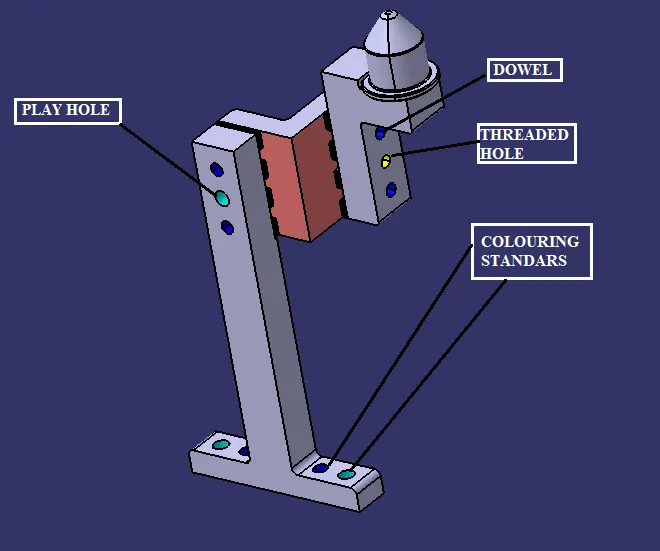
Fasteners Implementation:
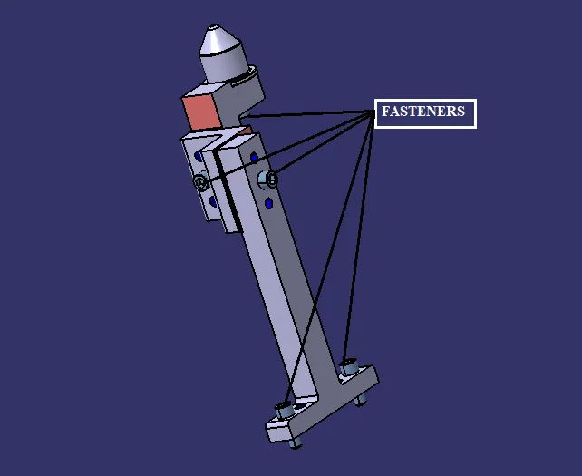
Checking the nominality of the UNIT:
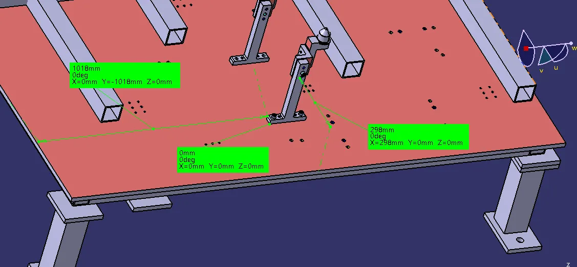
PIN UNIT:
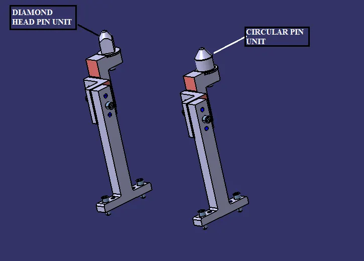
Proper Renaming of Parts:
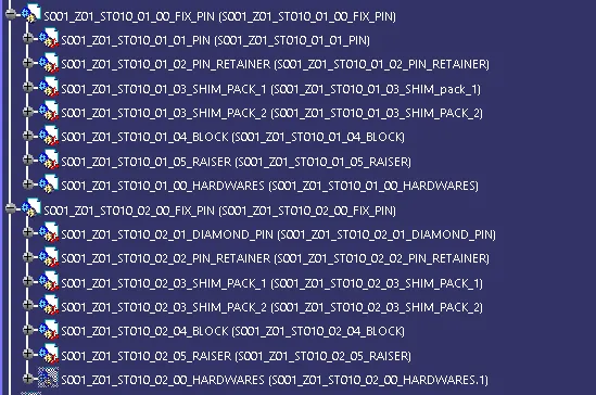
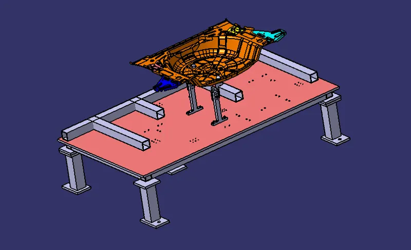
FIG:PIN UNIT WITH BASE UNIT AND COMPONENT
POWER CLAMP UNIT
3-2-1 principle: Our ultimate intention for using pin unit is to fix the work piece so that it does not deviate from the position while the operation is being performed on it. For this reason we use 3-2-1 principle.
Every component we know has 6 degrees of freedom. They are listed below:
- Translational motion along x-axis.
- Translational motion along y-axis.
- Translational motion along z-axis.
- Rotational motion along x-axis.
- Rotational motion along y-axis.
- Rotational motion along y-axis.
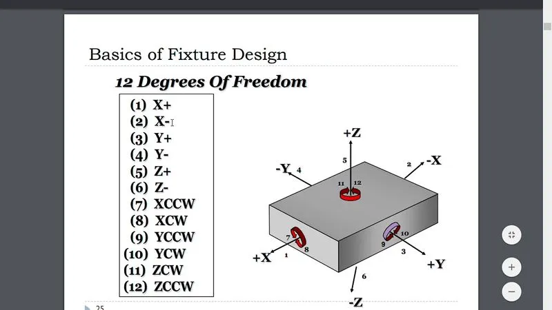
FIG. DEGREE OF FREEDOM
Degrees of freedom can be simply understood as the direction in which any component can move. These 6 degrees becomes 12 if we consider translation along negative and rotation in anti-clockwise direction too. That means, every component can move in all the direction when it is free. But processes like welding, stamping or others and in fact every other cannot be carried out on such free to move body for obvious reasons. Thus the body must be constrained in all the major direction in order for the workman to work upon it. This constrain on motion is achieved by 3-2-1 principle.
In 3-2-1 principle we make use of locating pins in the given order to fix it on a fixture:
- 3 pins are located on the bottom side of the component. These pins constrain the translational motion of the body in z direction and rotational motion along x-axis and y-axis. Thus 3 degrees are restricted. But the body still can rotate along z-axis and translate in x-axis and y-axis.
- 2 pins are located on the back side of the component. These pins constrain the translational motion along x-axis and rotational motion along z-axis. Thus we have constrained 5 degrees in total. But translation along y-axis is still possible.
- 1 pin located on the adjacent side of the 2 pins we can constrain the last degree that is translation along y-axis.
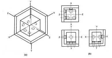
FIG. LOCATING PINS
Thus we can constrain all the degrees of freedom of a body using 3-2-1 principle which used 6 pins for the same.
When we use clamps we restrict following motions:
- Translational motion along z-axis.
- Rotational motion along x-axis.
- Rotational motion along y-axis.
sign two Rest units and three Power Clamp units with different Riser, Blade and Clamp arm.
CLAMPING: The car panel will rest on the rest unit, Also it resists the clamping force of the finger & thus clamp the car panel.
RESTING: The car panel will rest on the rest unit, Also it resists the clamping force of the finger & thus clamp the car panel.
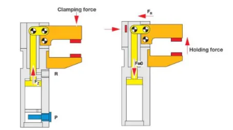
FORCES ACTS IN CLAMP & REST UNIT:
To design a clamp unit we have considered some forces which acts in clamp unit for clamping purpose. The forces acts in clamp units are,
- Clamping force.
- Holding force.
Clamping force is not the same as holding force.
CLAMPING FORCE:
Clamping force signifies the force applied to the work piece by the drive mechanism via the clamp arm during gripping or clamping operations.
Clamping force (Fs) = 48 x S3 = Force in newton
HOLDING FORCE:
Holding force, on the other hand, denotes the maximum force, after locking the knee-lever (over-centre position), that can be applied by the work piece on the gripper/clamp arm without destroying the mechanism. Therefore, particular attention must be paid to the maximum holding force when, for example during the production process (welding, bonding), there is a possibility of distortion of the component or if the clamp arm is used as a fixed stop.
If the holding force specified in the technical details is exceeded, this will inevitably result in destruction of the mechanism, the clamp arm or the bearing position.
CLAMP UNIT:
- Clamps are versatile tools that serve to temporarily hold work securely in place.
- A Clamp unit is a unit designed to clamp/ hold the car panel at a certain location.
- Its purpose is to hold the panel at that place with the application of force.
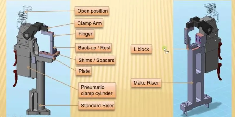
TYPES OF CLAMP UNIT:
- Power Clamp unit.
- Swivel cylinder clamp unit.
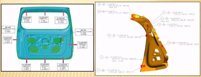
CLAMP PLAN:
- The customer provides the clamp plan which consists of the position of the clamp, pins, rests and dump etc.
- It has the exact coordinated of these components and in addition it also has the hole’s dimensions and tolerances.
- As this is a critical input data, it must not be modified.
- In case the spot for weld and the clamp position is nearby and it may create problem later and there is need to change the position of the clamp, the same must be done so with the permission of the customer as it will be easy for the customer to make changes from his side also.
NC block/Mylar:
- NC blocks or popularly also known as Mylar is the ones which hold the panel.
- It prevents the panel from deforming while welding.
- They always come in pairs.
- Top Mylar is known as clamping Mylar and bottom Mylar is known as resting Mylar.
Few points to remember about Mylar:
- Generally Mylar clamping block clamp cross section (the area which in contact panel) is considered as 20mmx20mm.
- Most of the OEM's /Tier 1 prefer Mylar to have 5mm allowance material for machining. Most of Mylar are CNC machined if it is clamping 3D profile.
- Depending on the angle of cross section, Mylar will be having shimming either in one direction or in 2 directions. General Thumb rule is if the section is inclined more than 15 deg or clamping surface is 3D profile then 2 direction shimming is provided. The reason being simple mathematics. Equation of inclined line/ plane will be having 2 parameters to controls and we control with shimming in 2 directions. Less than 15 deg does not mean that there are not 2 parameters. These are their but they are neglected if angle is less than 15 deg.
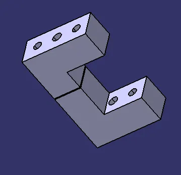
Shim:
- Shims are washers or thin strips of material used to align parts, make them fit or reduce wear.
- Shims are designed to fit in between blocks and fixtures to provide support or reach a dimension required in the assembly.
- Typically designed in a U shape matter so that they can fit between mounting screws. This shape helps to make them easy to install and remove or replace.
- Designers will use shims individually or as packs of 5, 6, or 7 pieces. Thicknesses range from 0.25mm to 2mm.
- Many assemblies require a tolerance to be hit in relation to a length or height; shims allow designers to hit these tolerances. They can be stacked between NAAMS NC blocks, L blocks, or pin retainers.
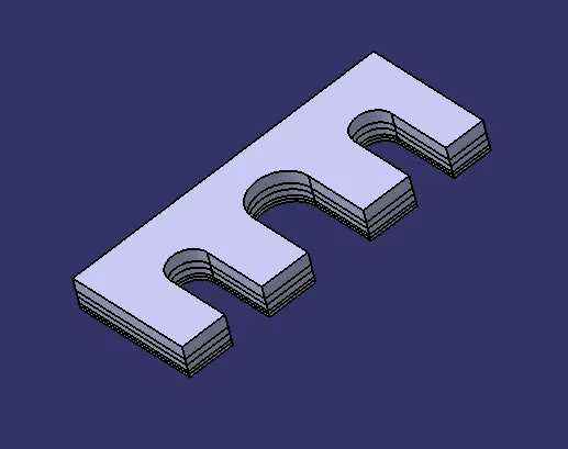
Riser:
- Riser is a structure generally used to mount the toggle clamp and rest, clamp Mylar and location pin and to give height to the assembly.
- It is not necessary to have one riser where all the parts of clamp or rest or location units are mounted.
- Risers can either be a standard part or make part.
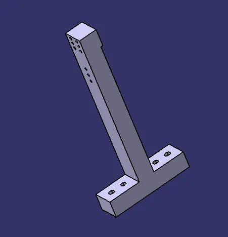
Blade:
- Blade is a plate which is attached to the riser and other components like cylinder, arm etc are mounted on it.
- It can either be a standard part or a make part
Standard parts/Bought out parts:
- Fasteners
- Clamp Cylinder
- Clamp arm
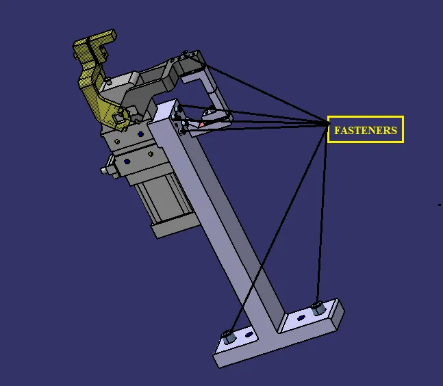
Fasteners: For this project ISO 4762 Hexagonal socket head cap screw were used with varying diameter and length. Mostly M8 screws with varying lengths are used but to fasten the riser to the base plate M10 or M12 are used. The length varies with respect to the thickness of the part that is to be fastened. This length is calculated by the formula:
Length of the screw= 1.5d+ distance between the start of surfaces to be fastened
For example in the below image, we are to fasten riser to the L-block. Distance between their surfaces is 25mm and we are using M8 screw.
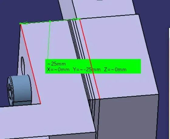
So the length of the screw will be= 25+1.5*8 i.e. 37mm. But standard available size is 40mm so we used that. And similar process was followed everywhere.
Clamp cylinder: A clamp is a pneumatic device which works with pressurized air. It is used to open and close the parts fixed to the clamp arm fixed to the clamp body.
- They are in general of 40, 50, 63 and 80 bore capacity.
- Horizontal clamp mounting opens up to 135deg.
- Vertical clamp mounting opens up to 105deg.
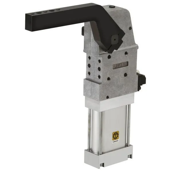
V 50.1, 63.1, 80.1 BR3 Vario Clamp: Vario clamp with toggle joint mechanism and continuously adjustable opening angle, Over-centre-lock, Enclosed aluminum housing, Oval-shaped cylinder in the sizes 50, 63, 80, Forked clamping arm, standard hole pattern for adapting contour blocks, Continuously adjustable opening angle 5°-135°, optional: Weld immune inductive sensing of closed and opened position (T12).
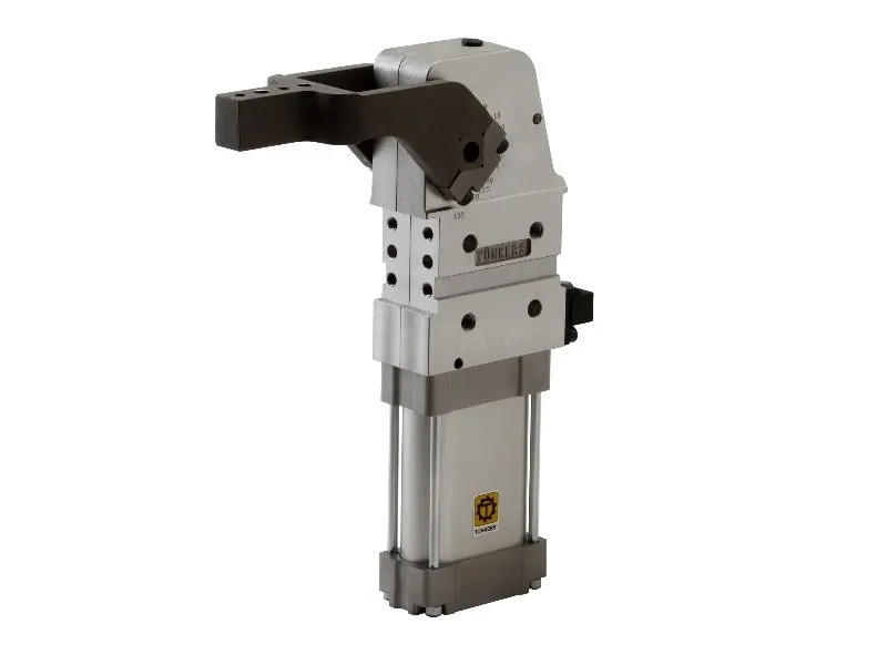
VU_63_BR2_A05_T12_135_GRAD_TUENKER: Vario clamp, Naams version, for clamping of medium and large body panels with stepless adjustable opening angle, integrated toggle lever mechanism, self-holding type. Enclosed aluminum housing, flat oval cylinder in sizes 50, 63, 80. Fork shaped clamp arm with standard hole pattern for receiving contour pieces. Opening angle variable from 5 ° -135 °. Options: - Inductive sensing, weld immune for open and closed position (T12) - Hand applied version.
Clamp arm: Clamp arm is a bought out part, to which all the movable parts are fixed. In general a clamp arm is a part of clamp cylinder.
- Clamp arms are different for different bore of cylinder
- Clamp arms are available in different hole pitch
- Clamp arms are available as:
Middle arm
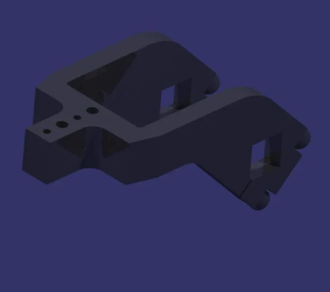
FIG. STANDARD CLAMP ARM (MIDDLE)
Right arm
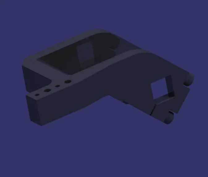
FIG. STANDARD CLAMP ARM (RIGHT)
Left arm
Fasteners Implementation:
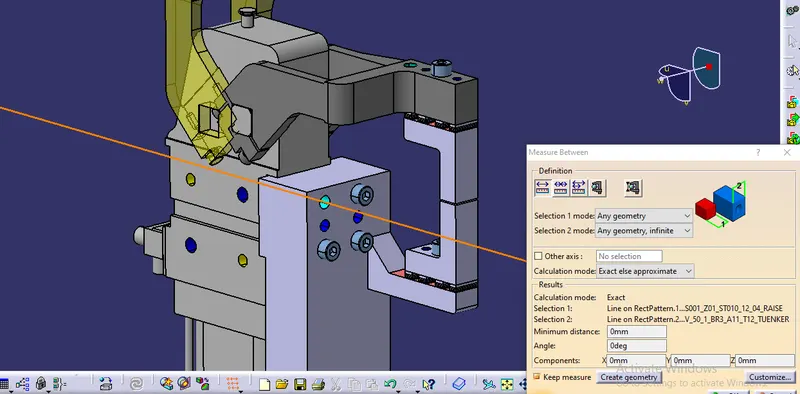
Checking the Hole Concentricity:
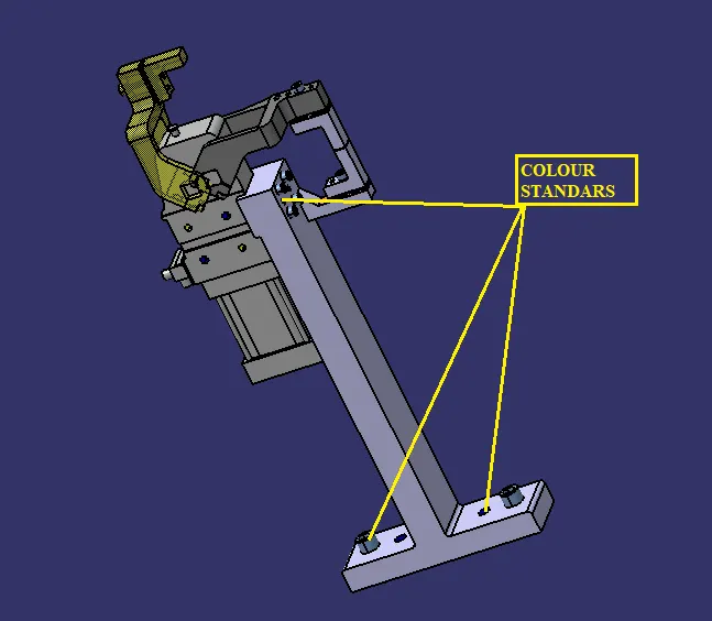
Colouring Holes as per the Standards:
Yellow - Threaded Holes
Blue - Dowel Holes
Indicating the Machining Area:
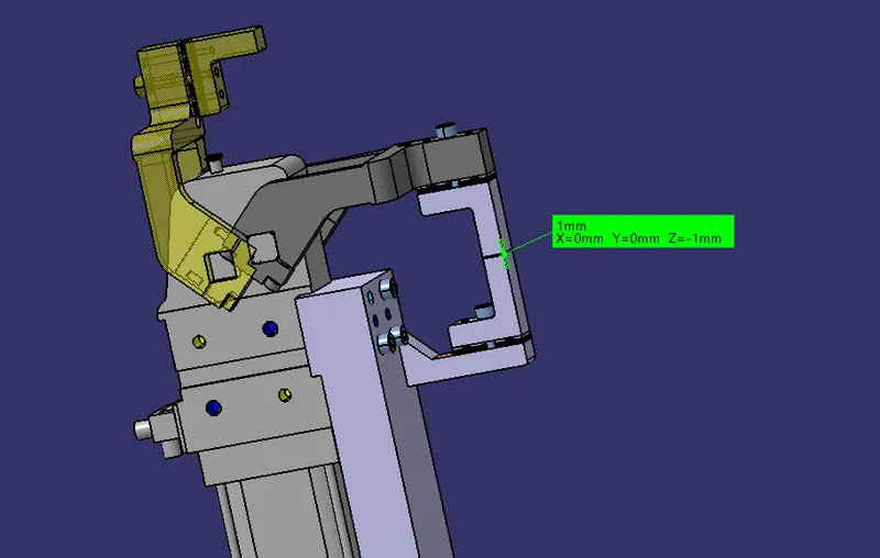
Mylars Splitting as per the Panel Profile:
Checking the nominality of the unit:
Renaming of all the Parts of POwer Clamp Unit:
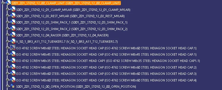
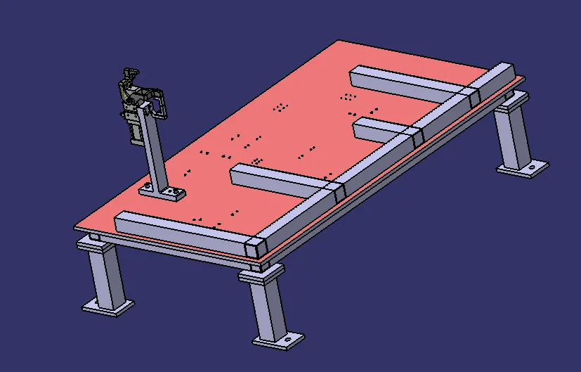
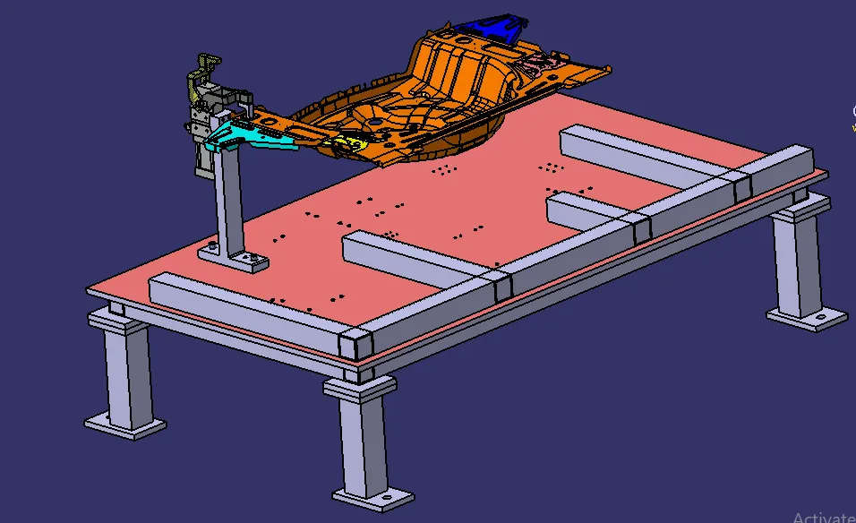
FIG:CLAMP UNITWITH BASE AND COMPONENT
SWIVEL CLAMP UNIT:
Swivel Clamps :
The primary components of the clevis clamp include clamp arm, blade, cylinder, angle riser, locator block, and finger. Swivel clamps shall typically be designed with the center of the clamp cylinder, the center of the locator, and the center of the clamp arm on a common line. However, it is acceptable to offset the clamp point from the clamp cylinder to allow for improved access for welding and part load and unload.
The clamp arm shall be welded construction including a 20.0mm thick arm with an integral pivot to accommodate a 19.50mm wide Swivel. The female portion of the clevis shall always be part of the arm. The male portion of the Swivel shall always be part of the blade.
Design of Swivel Clamp unit:
- Study the PLP (Principal location Points) data along with the nearby spot data.
- Depending on the angle of cross section. Mylars will be having shimming either in one direction or in 2 directions. General thumb rule if the section is inclined more than 150 or clamping surface is 3D profile then 2 direction shimming are provided
- Take an overview of the working height if you're having manual welding. For robotic welding also it's important to see the working height in consideration of the robotic gun, turntable height if manual loading is done.
- Put the proper gun at the spot location. If process engineer has gun shape stick to X, C or Y type of gun. Do the proper gun study and place the gun as per the Geo or re-spot decision and operator approach. Once basic gun is placed considering the throat depth and throat gap start building the clamp and rest block at the PLP.
- Panel section creation: Take a section at PLP either in clamp opening direction or normal direction Sections should be normal to base. Panel section through X, Y or Z direction passing through PLR Section will help it finalizing the shape of clamp and rest block. Most importantly used for finalization of gun shape.
- Finalization of a base plate plane: Consider following things before deciding the base plate Height of maximum and minimum weld spot from the floor. No gun arm should touch the base plate. Operator ergonomic while accessing all the spots.
- Construction of Rest and Clamp block: If standard Mylar has to be used (Few companies make standard height and length of steel blank with few holes and dowels for clamping) they select the proper blank size as per the requirement consider 0.5 mm above the panel.
- Select the clamping cylinder as per the pivot point distance from the PLP Once clamp and rest block are built, start construction of mounting plate or lubrication structure as per the company standard to make the connection with the base plate, shimming is 2mm solid+3mm shim pack. In few companies 3mm shims are used. Make connection plate between rise and Mylar Material can be C45, Teflon, Aluminium or S-Gurn as per the customer requirement Generally S Gurn Mylars are made of more thickness.
Factors to be considered while designing a clamp unit:
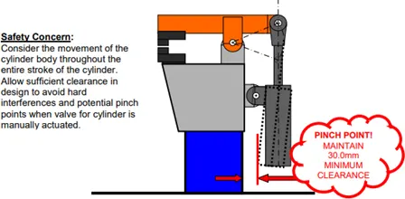
- There should be adequate space between the cylinder and another part like riser, car panel because cylinder moves or swing while opening and closing.
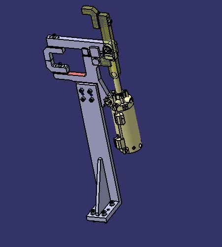
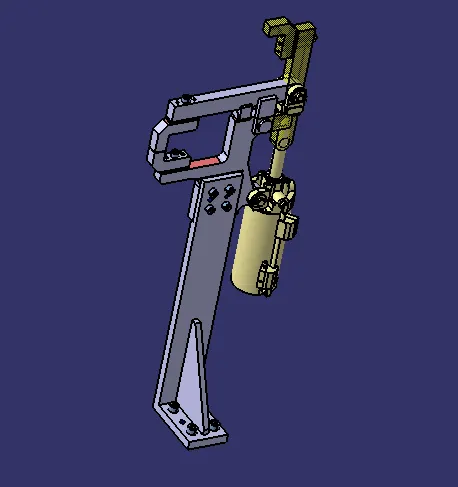
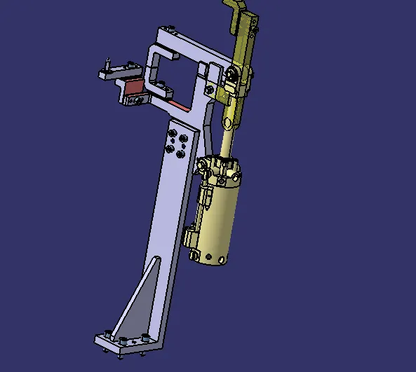
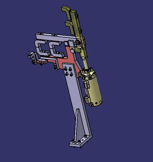
- Pin clam unit is used where two panels or components are located and clamp for welding.
- Clamp make is in such a way that it clamps two car panel at once.
- Every clamp Mylar should have rest Mylar.
- Clamp unit has shims in only in one direction.
- All parts should snap and butt properly to each other.
- Make sure that parts of the clamping unit are min 10 to 12 mm away from the car panel, so they don't damage the car panel.
- Design tree should be structured in a way that makes a part on the top and followed the standard part.
- Avoid any clash, it will not rise issue at assembly.
- The product design should be in such a way that it will be easy to make, assemble and quality check.
- We should preferably use quick acting clamps, the clamping method will not damage the work piece. The clamp should be open in such a way that clamp arm moves away from the operator.
- There must be adequate clearance for loading and unloading. So, the process becomes fast and easy. The Size variation must be accepted.
- Avoid sharp edges and corners, they can harm the operators and cause a serious injury. Provide chamfer or fillet to the corner.
- The fixture must possess sufficient rigidity and robustness. It should not vibrate as it can lead to unwanted movement of the work piece and tools.
- Must ensure security in the operation
Below are general parts of swivel clamp unit.
Clamp Cylinder:
Cylinder designation: In this unit we used Clevis cylinder for clamping designated as CKG_1B_63_100Y
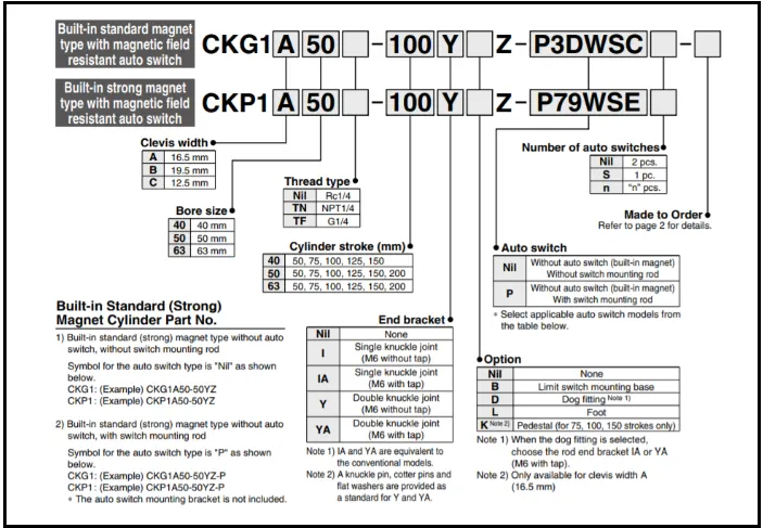
Nomenclature of cylinder as belows:
CKG1: Series of cylinder
B: Clevis width as 19.5 mm.
63: Bore size
100: Stroke of cylinder
Y: End bracket i.e. double knuckle joint (M6 without tap)
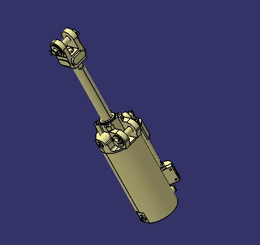
FIG:Clevis cylinder
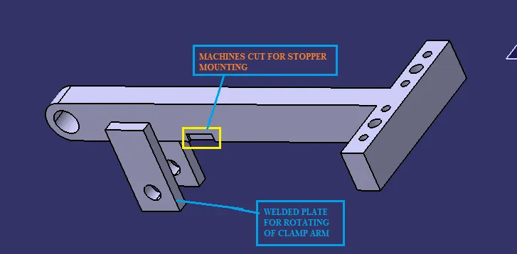
Clamp arm: It is part to which clamp mylar mounted & also clamp cylinder is attached to the end of arm with the use of clevis pin. It has two plates of 8 mm thickness welded & helps in rotating of clamp arm about pivoting point of blade.
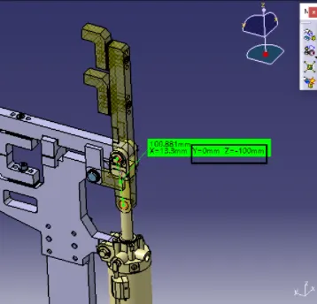
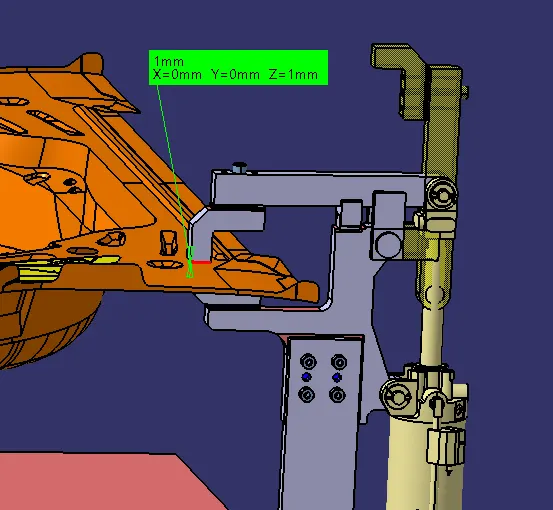
Below figure shows 100 mm stroke achieved & clamp arm end in line with cylinder rod. See Y & Z values.
NC block/Mylar:
- NC blocks or popularly also known as Mylar is the ones which hold the panel.
- It prevents the panel from deforming while welding.
- They always come in pairs.
- Top Mylar is known as clamping Mylar and bottom Mylar is known as resting Mylar.
Few points to remember about Mylar:
- Generally Mylar clamping block clamp cross section (the area which in contact panel) is considered as 20mmx20mm.
- Most of the OEM's /Tier 1 prefer Mylar to have 5mm allowance material for machining. Most of Mylar are CNC machined if it is clamping 3D profile.
- Depending on the angle of cross section, Mylar will be having shimming either in one direction or in 2 directions. General Thumb rule is if the section is inclined more than 15 deg or clamping surface is 3D profile then 2 direction shimming is provided. The reason being simple mathematics. Equation of inclined line/ plane will be having 2 parameters to controls and we control with shimming in 2 directions. Less than 15 deg does not mean that there are not 2 parameters. These are their but they are neglected if angle is less than 15 deg.
FIG: CLAMP &REST MYLAR
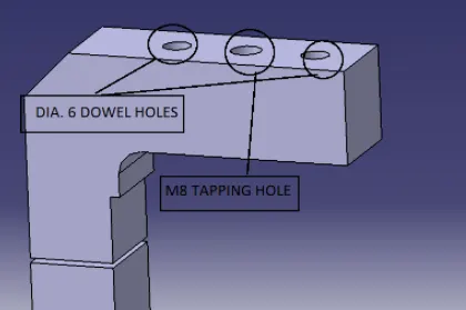
FIG: CLAMP &REST MYLAR
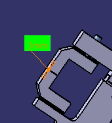
1mm is the component thickness.so the distance between the clamp and rest mylar is 1mm.
Stopper:
The function of stopper is to restrict motion of clamp arm. It avoids clamp arm to rotate beyond limit. It has two parts male & female.
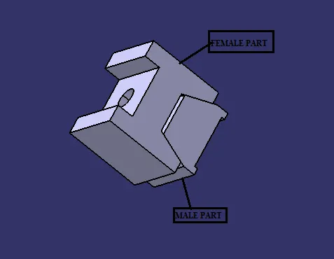
Blade: Blade is part to which all other units are attached for e.g. mylar, stopper, clamp cylinder, riser. Blade is designed according to position of all other parts.
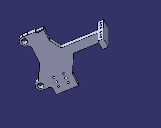
FIG: BLADE
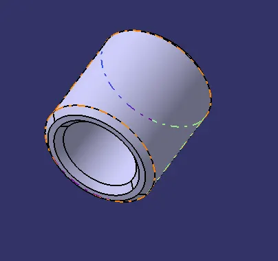
Bush: Bush is friction type bearing. It is lubricated with grease, oil. It permits relative motion between two mating parts. It is made of hard material also its ID & OD are precisely machined or grinded. It press fitted & after worn out it is replaced with new one instead of replacing other part which save cost. Mostly phosphor bronze or gun metal material used for making bush. In this unit three bushes are used of same internal (12 mm) & external diameter (18 mm) but different length.
Shim:
- Shims are washers or thin strips of material used to align parts, make them fit or reduce wear.
- Shims are designed to fit in between blocks and fixtures to provide support or reach a dimension required in the assembly.
- Typically designed in a U shape matter so that they can fit between mounting screws. This shape helps to make them easy to install and remove or replace.
- Designers will use shims individually or as packs of 5, 6, or 7 pieces. Thicknesses range from 0.25mm to 2mm.
- Many assemblies require a tolerance to be hit in relation to a length or height; shims allow designers to hit these tolerances. They can be stacked between NAAMS NC blocks, L blocks, or pin retainers.
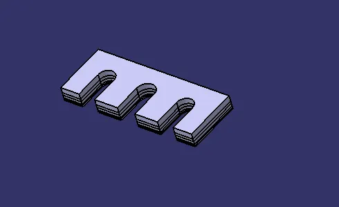
FIG: SHIMS
Riser:
- Riser is a structure generally used to mount the toggle clamp and rest, clamp Mylar and location pin and to give height to the assembly.
- It is not necessary to have one riser where all the parts of clamp or rest or location units are mounted.
- Risers can either be a standard part or make part.
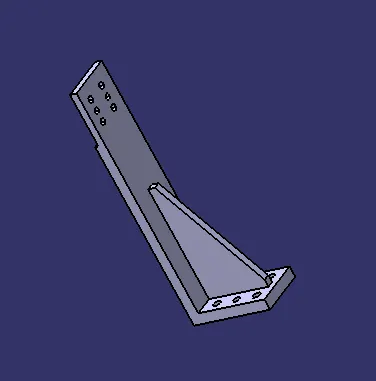
Implementation of fasteners:
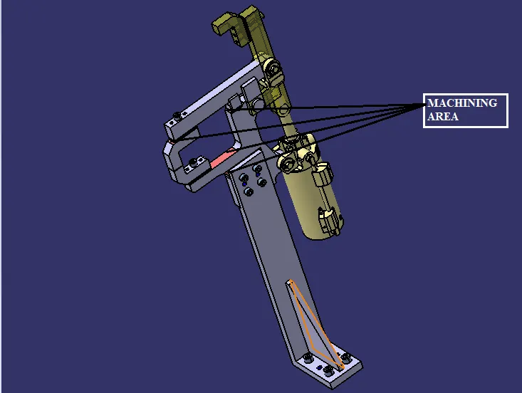
Holes Colouring as per the Standards:
Yellow - Threaded hole
Blue - Dowel hole
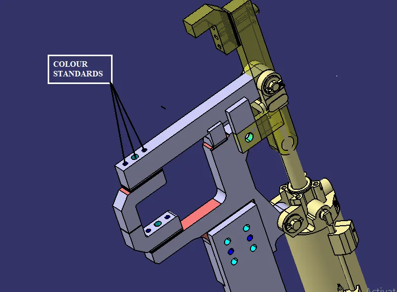
Indicating the Machined area:
Checking the nominality of the UNIT:
Mylars Splitting as per the Panel profile:
Checking the Nominality of all the Parts:
Renaming of all the Parts:
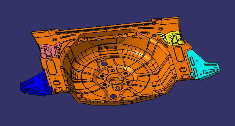
PANEL:
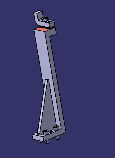
REST UNIT:
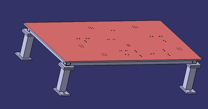
Base Unit
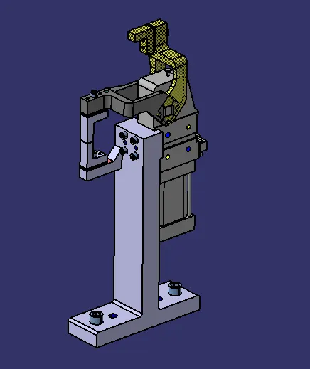
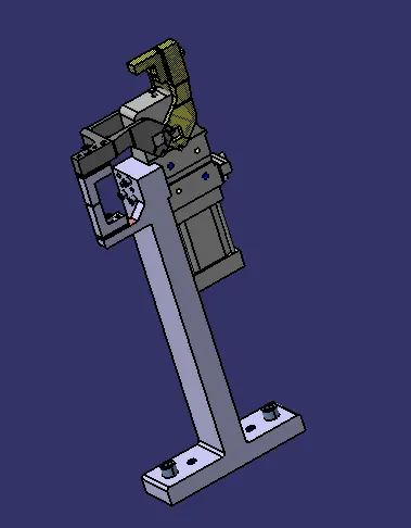
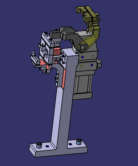
Power Clamp Units:
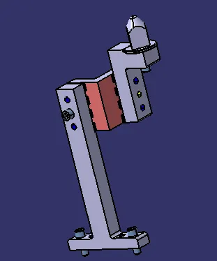
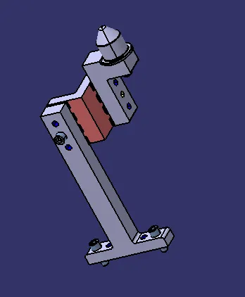
Pin Units:
Swivel Clamp Units:
Pin Clamp Units:
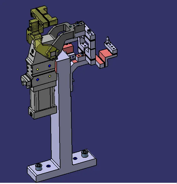
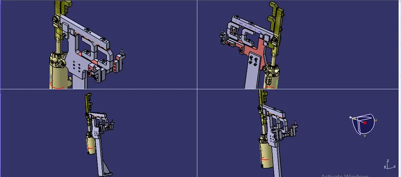
Positioning of the units on the Base Plate:
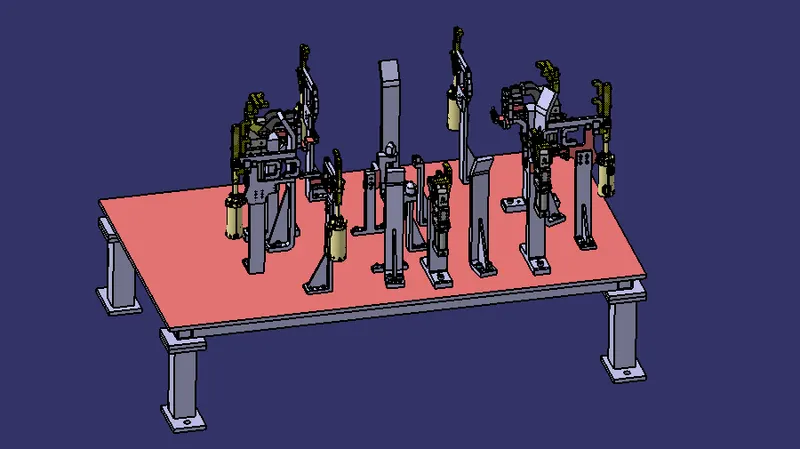
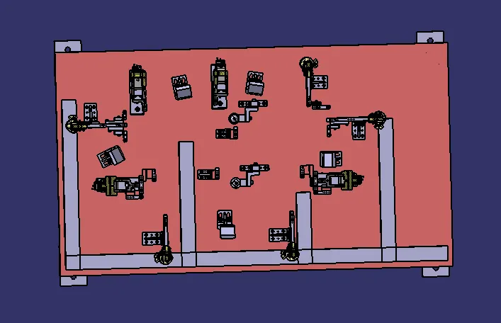
FINAL IMAGE OF THE FIXTURE:

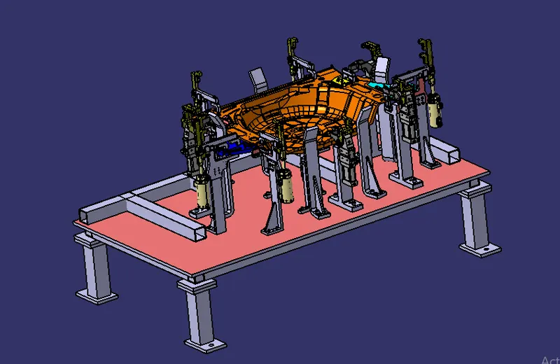
CONCLUSION:
Hence, 3D finishing is performed on the designed Assembly of Fixtures and Rough Locators were designed for the given panel.