Week 10:- 2D Detailing Challenge
AIM
To Draft a Key Sheet for the Complete Fixture assembly and Draft a Base Unit and the Fix Pin Unit drawings with all child parts for the complete Fixture asse
Procedure:
Key sheet for complete fixture:
NOTE:
- To drafting a part, there's always been a standard procedure to do it.
- Must have three start in a drawing and there are different standards to start up a drawing.
- 2 hole starts and one machining start and three machining start. based on customer standards.
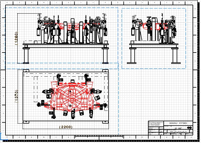
The front view, top view, and right side view are shown for the complete fixture assembly. The overall dimensions are provided and the open positions are represented with dotted lines.
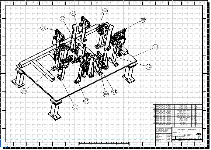
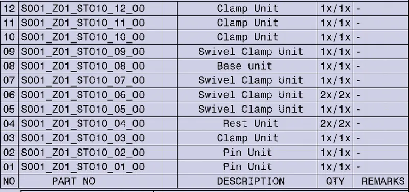
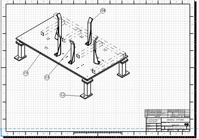
Isometric View of the complete fixture assembly with all the units marked.
2D Detailing of the base unit.
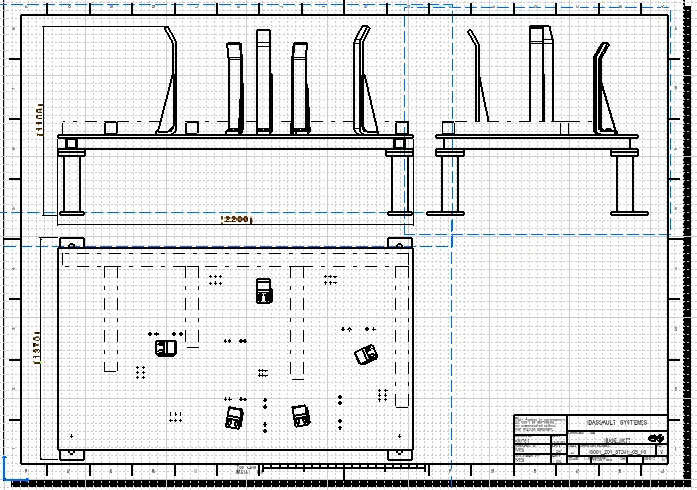
The front view, top view, and right side view are shown for the base unit. The overall dimensions are provided.

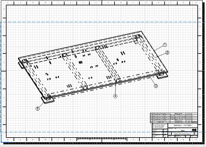
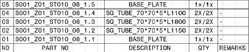
Isometric view of the Baseplate with all the subparts marked.
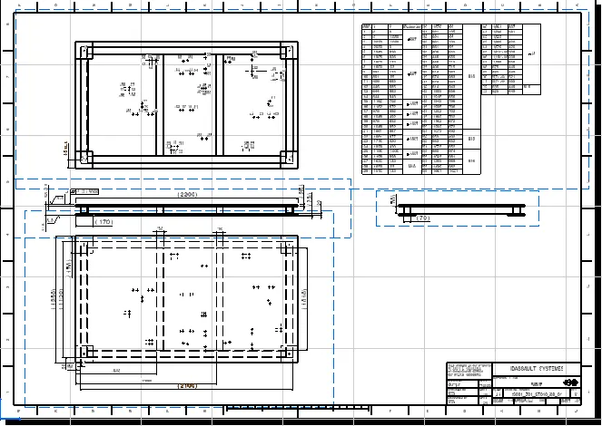
The front view, top view, and right side view are shown for the base plate unit. The overall dimensions are provided and the hole data is given for machining.
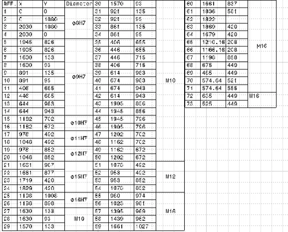
- The surface that has to be machined is provided with a surface roughness value of 3.2.
- The extra raw material is shown in the dimension on the machining surface.
- The hole data provided is with respect to the tooling hole as a reference.
- All the holes must have a nominal dimension. It is advised to do manual drilling if the holes are not nominal at some places due to design consideration.
ROUGH LOCATORS1
ROUGH LOCATOR 2
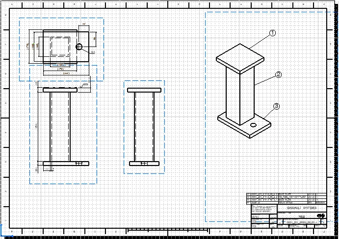
PEDASTAL
2D Detailing of the Fix Pin Unit 1
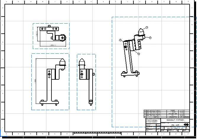
The front view, top view, and right side view are shown for the FIX PIN unit. The overall dimensions are provided and the hole data is given for machining.

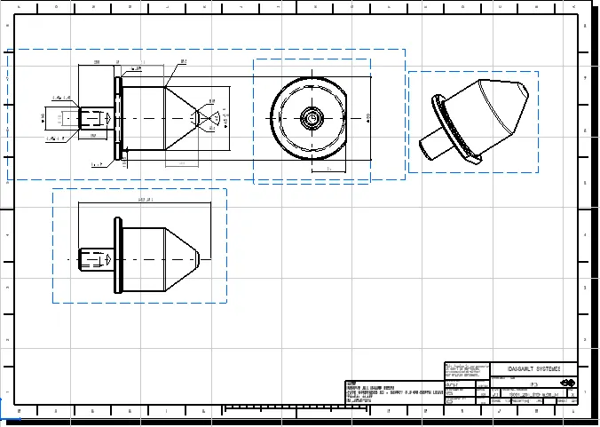
PIN
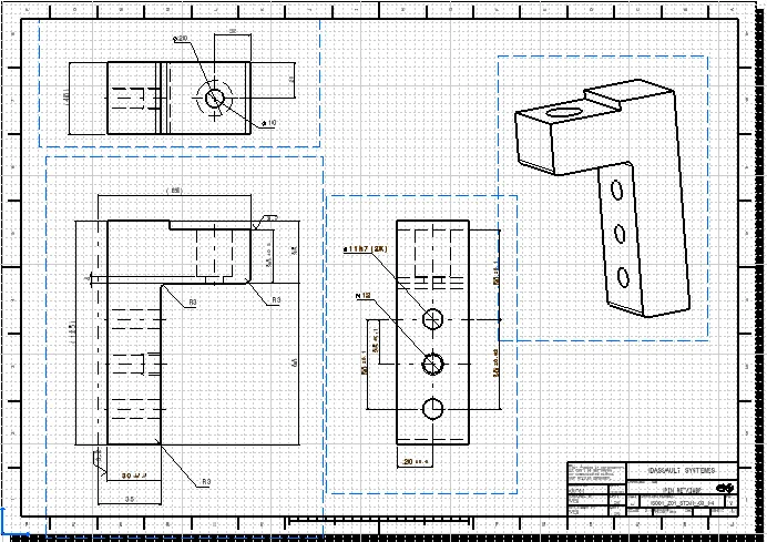
PIN RETAINER
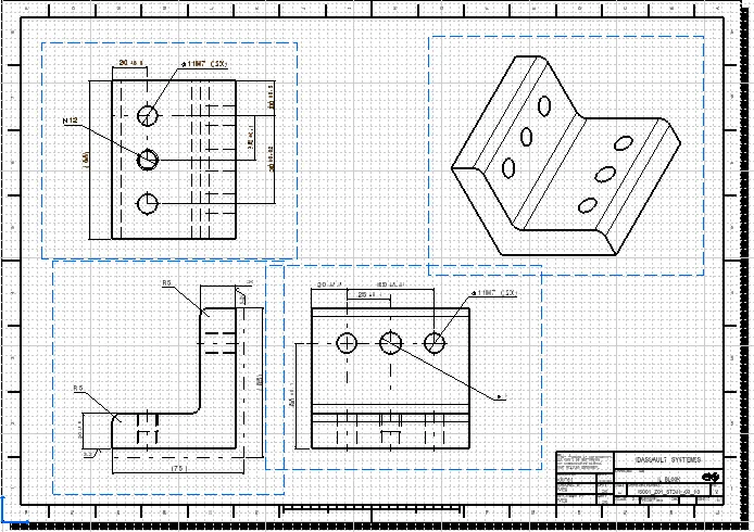
L BLOCK
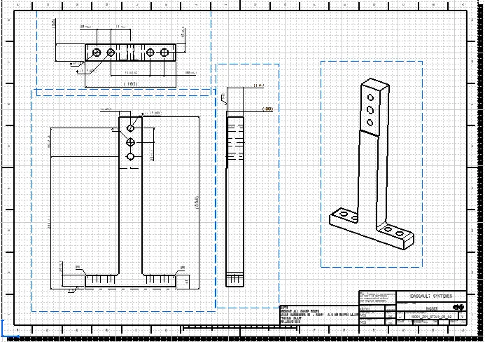
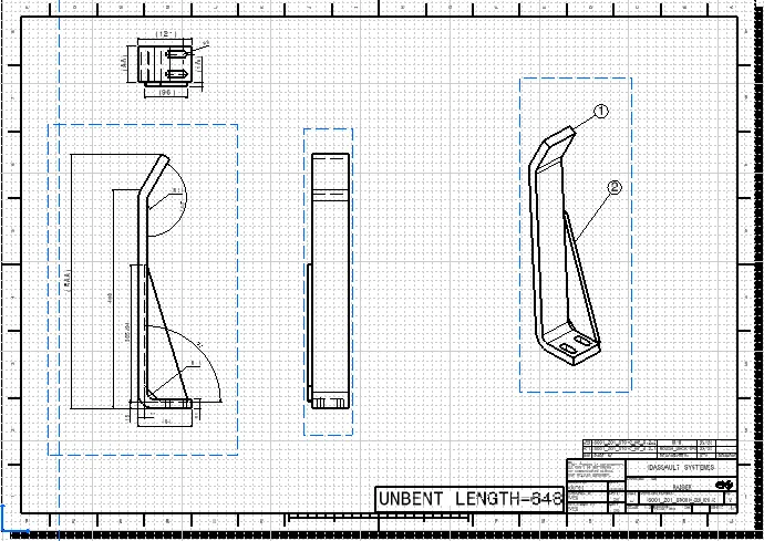
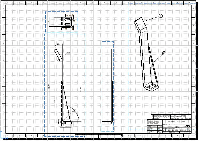
RAISER
CONCLUSION:
To draft a key sheet for the complete fixture assembly created in challenge 8 and to draft a base unit and the fixed pin unit drawings with all child parts for the complete fixture assembly from challenge 8 has been done.