Week 6:- Clamp Unit & Pin-Clamp Unit Design Challenge
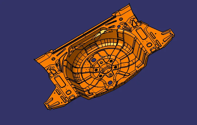
OBJECTIVE: To design 3 types of Swivel Clamp unit and 1 Pin-Clamp unit with different Riser, Blade and Clamp arm while maintaining the stroke of cylinder as 100mm.
INPUT
FUNDAMENTALS:
3-2-1 principle: Our ultimate intention for using pin unit is to fix the work piece so that it does not deviate from the position while the operation is being performed on it. For this reason we use 3-2-1 principle.
Every component we know has 6 degrees of freedom. They are listed below:
- Translational motion along x-axis.
- Translational motion along y-axis.
- Translational motion along z-axis.
- Rotational motion along x-axis.
- Rotational motion along y-axis.
- Rotational motion along y-axis.
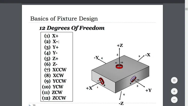
FIG. DEGREE OF FREEDOM
Degrees of freedom can be simply understood as the direction in which any component can move. These 6 degrees becomes 12 if we consider translation along negative and rotation in anti-clockwise direction too. That means, every component can move in all the direction when it is free. But processes like welding, stamping or others and in fact every other cannot be carried out on such free to move body for obvious reasons. Thus the body must be constrained in all the major direction in order for the workman to work upon it. This constrain on motion is achieved by 3-2-1 principle.
In 3-2-1 principle we make use of locating pins in the given order to fix it on a fixture:
- 3 pins are located on the bottom side of the component. These pins constrain the translational motion of the body in z direction and rotational motion along x-axis and y-axis. Thus 3 degrees are restricted. But the body still can rotate along z-axis and translate in x-axis and y-axis.
- 2 pins are located on the back side of the component. These pins constrain the translational motion along x-axis and rotational motion along z-axis. Thus we have constrained 5 degrees in total. But translation along y-axis is still possible.
- 1 pin located on the adjacent side of the 2 pins we can constrain the last degree that is translation along y-axis.
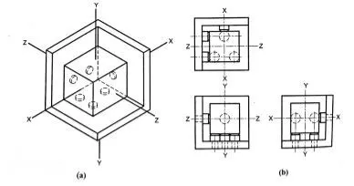
FIG. LOCATING PINS
Thus we can constrain all the degrees of freedom of a body using 3-2-1 principle which used 6 pins for the same.
When we use clamps we restrict following motions:
- Translational motion along z-axis.
- Rotational motion along x-axis.
- Rotational motion along y-axis.
sign two Rest units and three Power Clamp units with different Riser, Blade and Clamp arm.
Clamp unit: Clamp unit is unit designed to clamp / hold the car panel with NC blocks/ mylar/ rest by using a pneumatic clamp cylinder & below are different parts of a clamp unit in general. Usually clamp open position is 90°. Fingers are attached to clamp mylar. In clamp unit shim to one side is more enough because it will restrict translation motion in upward & downward direction only. There is another type of clamp unit knows as swivel type. There is pivot pin around which clamp arm rotate.
Factors should be considered while designing a clamp unit:
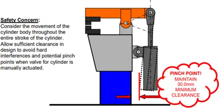
- There should be adequate space between the cylinder & another part like riser, car panel because cylinder moves or swing while opening & closing
- Pin clamp unit used where two panel or component are located for welding.
- Clamping make in such way that it clamps two car panels at once
- All parts should snap & butt properly to each other.
- Make sure that parts of the clamping unit are 10 to 12 mm away from car panel so they do not damage car panel
- Avoid any clash. It will not arises issue at assembly.
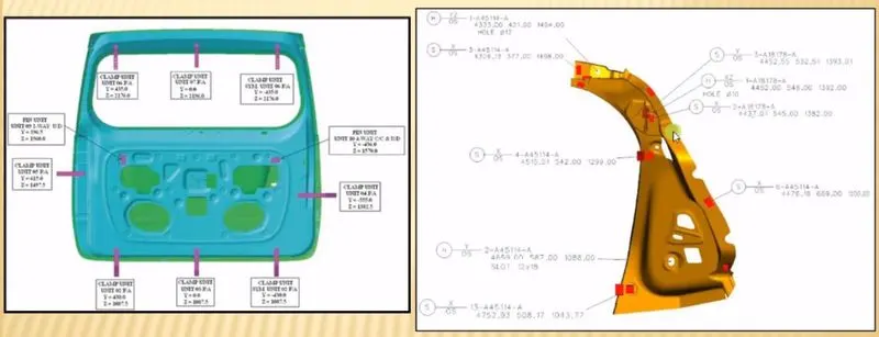
CLAMP PLAN:
- The customer provides the clamp plan which consists of the position of the clamp, pins, rests and dump etc.
- It has the exact coordinated of these components and in addition it also has the hole’s dimensions and tolerances.
- As this is a critical input data, it must not be modified.
- In case the spot for weld and the clamp position is nearby and it may create problem later and there is need to change the position of the clamp, the same must be done so with the permission of the customer as it will be easy for the customer to make changes from his side also.
Swivel Clamps :
The primary components of the clevis clamp include clamp arm, blade, cylinder, angle riser, locator block, and finger. Swivel clamps shall typically be designed with the center of the clamp cylinder, the center of the locator, and the center of the clamp arm on a common line. However, it is acceptable to offset the clamp point from the clamp cylinder to allow for improved access for welding and part load and unload.
The clamp arm shall be welded construction including a 20.0mm thick arm with an integral pivot to accommodate a 19.50mm wide Swivel. The female portion of the clevis shall always be part of the arm. The male portion of the Swivel shall always be part of the blade.
Below are general parts of swivel clamp unit.
Clamp Cylinder:
Cylinder designation: In this unit we used Clevis cylinder for clamping designated as CKG_1B_63_100Y
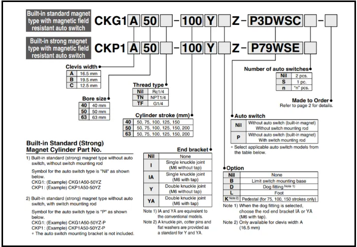
Nomenclature of cylinder as belows:
CKG1: Series of cylinder
B: Clevis width as 19.5 mm.
63: Bore size
100: Stroke of cylinder
Y: End bracket i.e. double knuckle joint (M6 without tap)
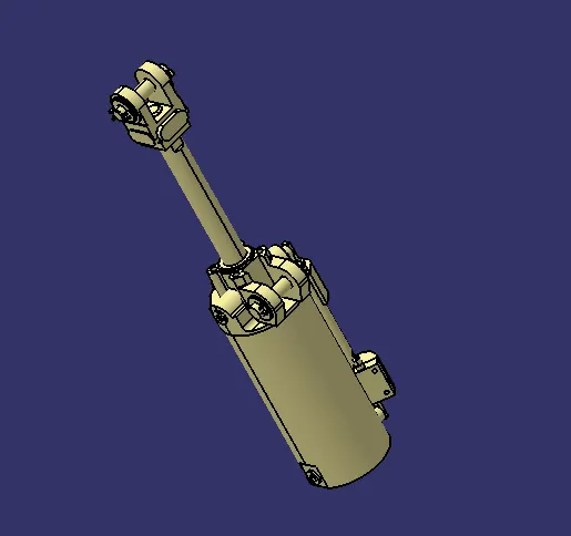
FIG:Clevis cylinder
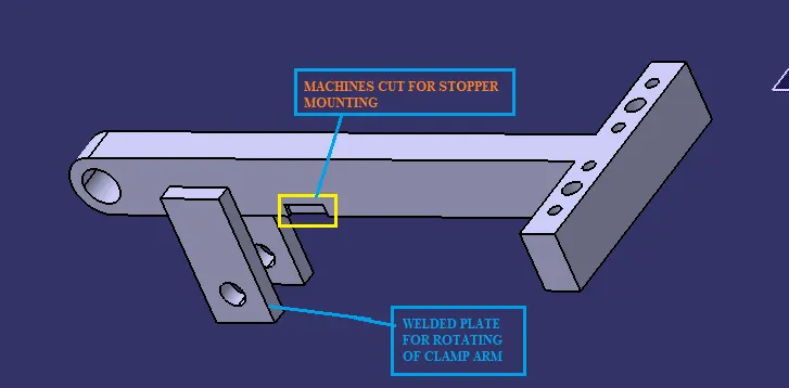
Clamp arm: It is part to which clamp mylar mounted & also clamp cylinder is attached to the end of arm with the use of clevis pin. It has two plates of 8 mm thickness welded & helps in rotating of clamp arm about pivoting point of blade.
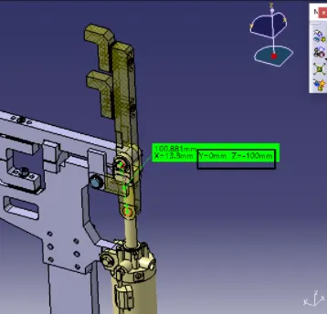
Below figure shows 100 mm stroke achieved & clamp arm end in line with cylinder rod. See Y & Z values.
NC block/Mylar:
- NC blocks or popularly also known as Mylar is the ones which hold the panel.
- It prevents the panel from deforming while welding.
- They always come in pairs.
- Top Mylar is known as clamping Mylar and bottom Mylar is known as resting Mylar.
Few points to remember about Mylar:
- Generally Mylar clamping block clamp cross section (the area which in contact panel) is considered as 20mmx20mm.
- Most of the OEM's /Tier 1 prefer Mylar to have 5mm allowance material for machining. Most of Mylar are CNC machined if it is clamping 3D profile.
- Depending on the angle of cross section, Mylar will be having shimming either in one direction or in 2 directions. General Thumb rule is if the section is inclined more than 15 deg or clamping surface is 3D profile then 2 direction shimming is provided. The reason being simple mathematics. Equation of inclined line/ plane will be having 2 parameters to controls and we control with shimming in 2 directions. Less than 15 deg does not mean that there are not 2 parameters. These are their but they are neglected if angle is less than 15 deg.
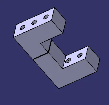
FIG: CLAMP &REST MYLAR
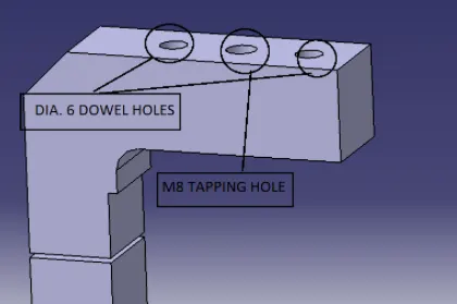
FIG: CLAMP &REST MYLAR
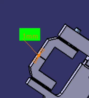
1mm is the component thickness.so the distance between the clamp and rest mylar is 1mm.
Stopper:
The function of stopper is to restrict motion of clamp arm. It avoids clamp arm to rotate beyond limit. It has two parts male & female.
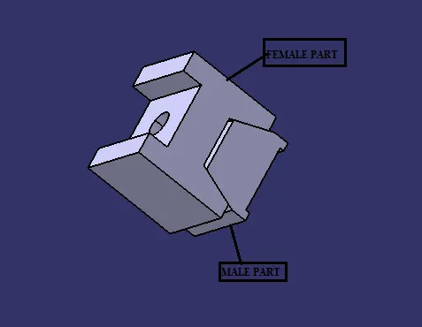
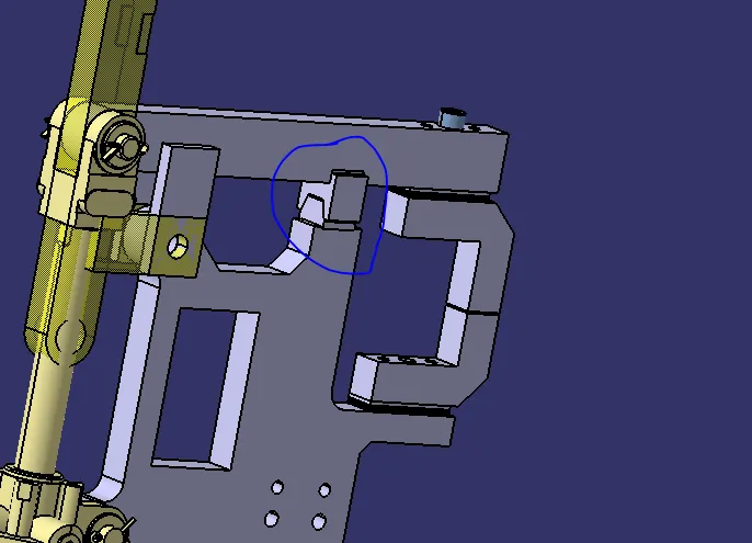
Blade: Blade is part to which all other units are attached for e.g. mylar, stopper, clamp cylinder, riser. Blade is designed according to position of all other parts.
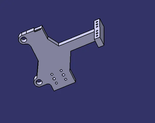
FIG: BLADE
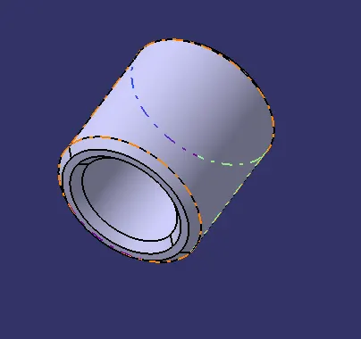
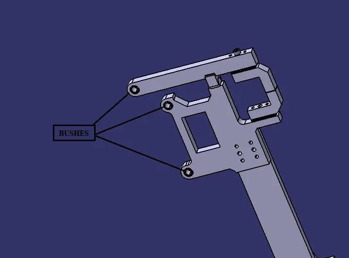
Bush: Bush is friction type bearing. It is lubricated with grease, oil. It permits relative motion between two mating parts. It is made of hard material also its ID & OD are precisely machined or grinded. It press fitted & after worn out it is replaced with new one instead of replacing other part which save cost. Mostly phosphor bronze or gun metal material used for making bush. In this unit three bushes are used of same internal (12 mm) & external diameter (18 mm) but different length.
Pin
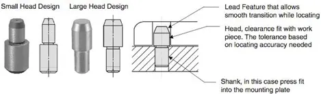
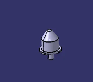
- It locates the car panel . it can either be a make part or a standard part .
- A pin should have a grinding surface on shaft with fits onto which the pin retainer is fixed .
- The mounting surface of pin should be fine machined surface .
- It should have step machine surface to lock rotation which matches with pin retainer .
- The mounting surface of pin retainer to the block should be machined surface .
- All machined planes should be perpendicular to the axis of shaft .
- Pin must have fastening provision like tapped hole from bottom or a V groove from side .
- A pin must be hardened ( heat treatment ) (55 to 60 HRC) and black oxide finished in general .
- Material - Hardened material like C45 , 16MNCR5 , 20MNCR5 , EN31 etc .
- Surface finish - black oxide , Zinc coating , Chrome plating .
Typically, locating pins are used for controlled, fine tolerance positioning of a, For example, a pallet that is moved along one axis, where the drive mechanism is not accurate and stable enough to place it in a position sufficiently accurate to execute a particular process, the use of locating pins may be the best solution.
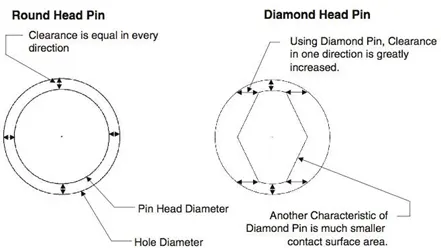
The Diamond Shape is a critical feature that helps with machining inaccuracies and smoother locating When two round headpins are installed onto one plate, the distance between two mounting holes must be extremely precise and even then, the workpiece will not be placed on the base as easily as it would with the use of a diamond shape pin.
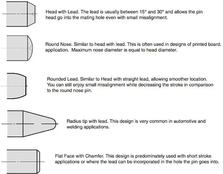
There are several styles of Pin Head They serve different purposes and can be utilized in a variety of applications.
Shim:
- Shims are washers or thin strips of material used to align parts, make them fit or reduce wear.
- Shims are designed to fit in between blocks and fixtures to provide support or reach a dimension required in the assembly.
- Typically designed in a U shape matter so that they can fit between mounting screws. This shape helps to make them easy to install and remove or replace.
- Designers will use shims individually or as packs of 5, 6, or 7 pieces. Thicknesses range from 0.25mm to 2mm.
- Many assemblies require a tolerance to be hit in relation to a length or height; shims allow designers to hit these tolerances. They can be stacked between NAAMS NC blocks, L blocks, or pin retainers.
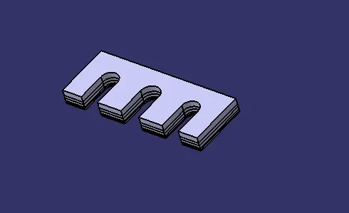
FIG: SHIMS
Riser:
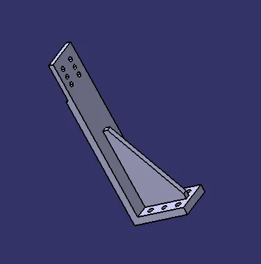
- Riser is a structure generally used to mount the toggle clamp and rest, clamp Mylar and location pin and to give height to the assembly.
- It is not necessary to have one riser where all the parts of clamp or rest or location units are mounted.
- Risers can either be a standard part or make part.
Hardware: These are standard parts. Parts are assembled together with help of washer and bolt. for better assembly should use two dowels and four bolts for riser and blade. Where for bolting one part should have tapping hole and on other part simple hole (1 to 2 mm larger from bolt size.)
Length of the bolt is decided by width of part + (1.5*D)
For ex. where
L=Length of Bolt
D=diameter of bolt to be used
Let’s, take M8 Bolt
L= 25 + (1.5 * 8)
L=25+12
L=37 mm.
Dowel pins: These are standard part. There are various types of dowel pin like split, parallel, taper, clevis, and spring, grooved. Dowel pins are used to locate part precisely & to restrict movements. For mylar dia. 6 or 8 dowel pins should be used. For blade, shimming block dia.8 dowel pin should be used & for riser base dia. 10 or 12 pins are used.
Washer: Standard steel grade A plain normal series washer used.
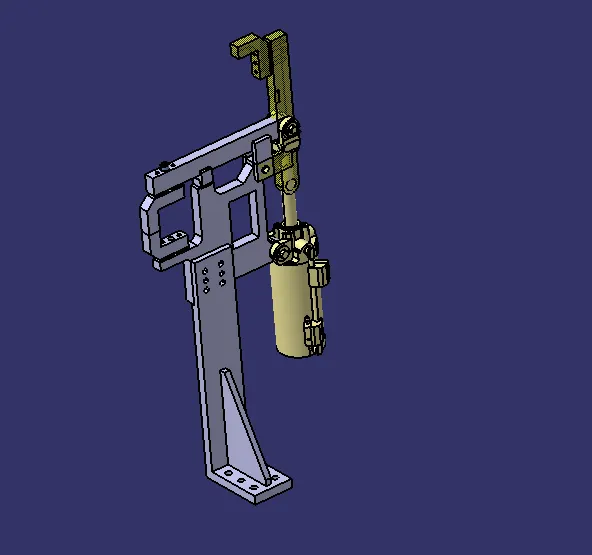
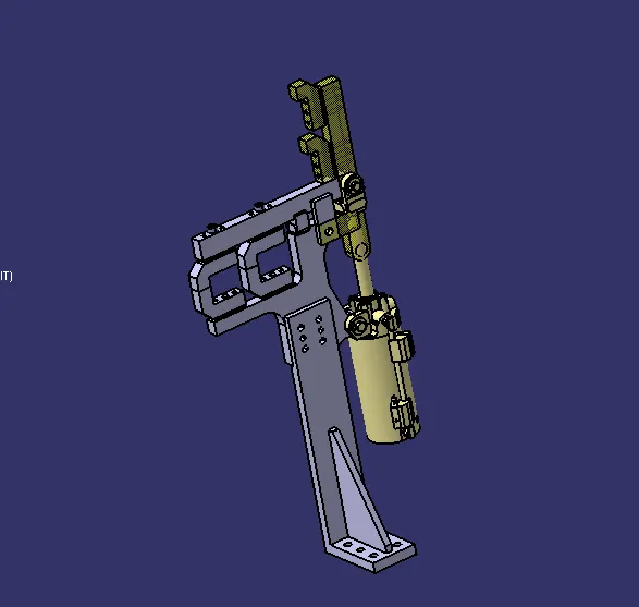
FIG:S001_Z01_ST010_01_00_CLAMP_UNIT
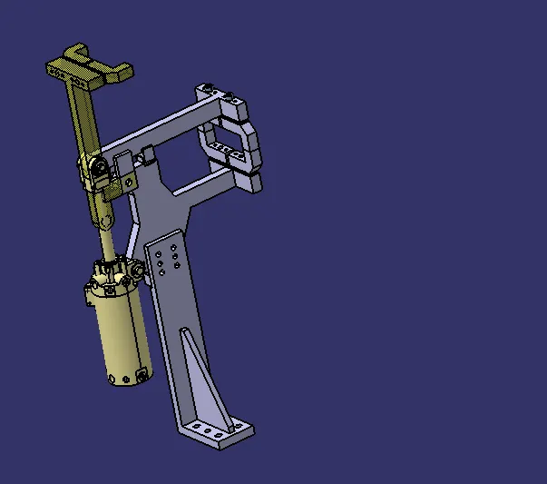
S001_Z01_ST010_02_00_CLAMP_UNIT
S001_Z01_ST010_03_00_CLAMP_UNIT
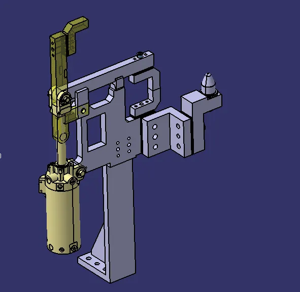
S001_Z01_ST010_04_00_PIN_CLAMP_UNIT
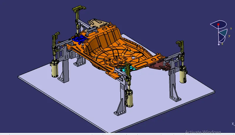
FIG: COMPONENT WITH CLAMP UNITS AND BASE UNIT
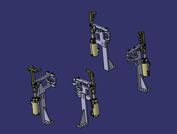
FIG: CLAMP UNITS
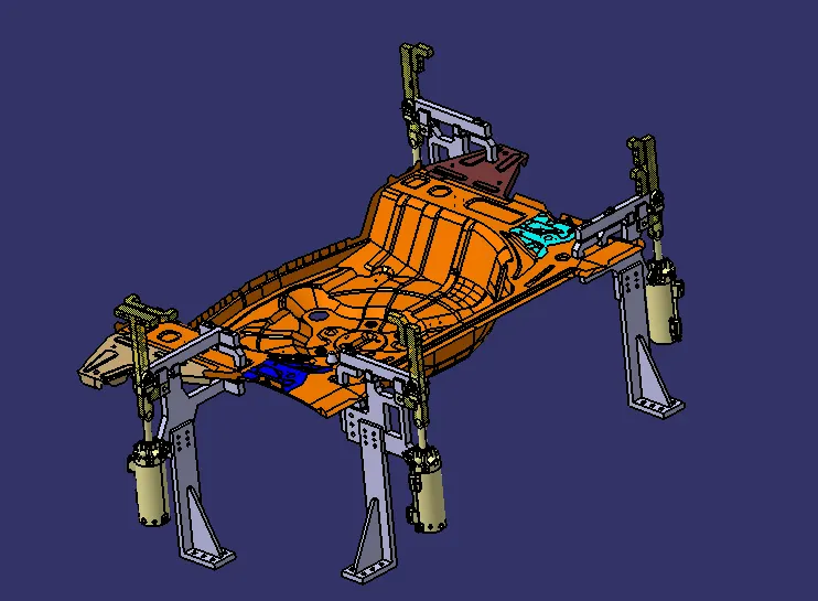
FIG: COMPONENT WITH CLAMP UNITS
CONCLUSION:
Hence as per objective, the 3 different types of SWIVEL clamp unit by validating & pin clamp units are designed in catia v5 software.