Week 8 - Challenge 3 - Switch Bezel Design
Switch Bezel Design
Aim:
To create the switch bezel plastic component through the given class-A-surface and at the end performing the draft analysis on the model.
Objectives-
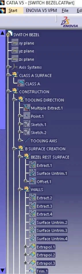
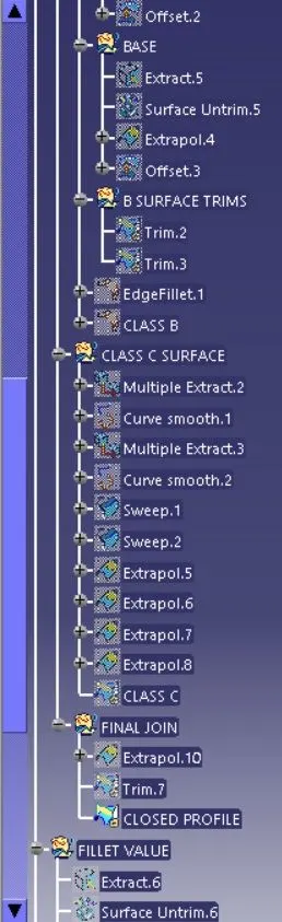
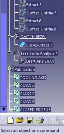
- To ensure proper tree structure is followed.
- Geometrical sets should have a proper name based on the sketches present inside of it.
- All the sketches should be created under geometrical set.
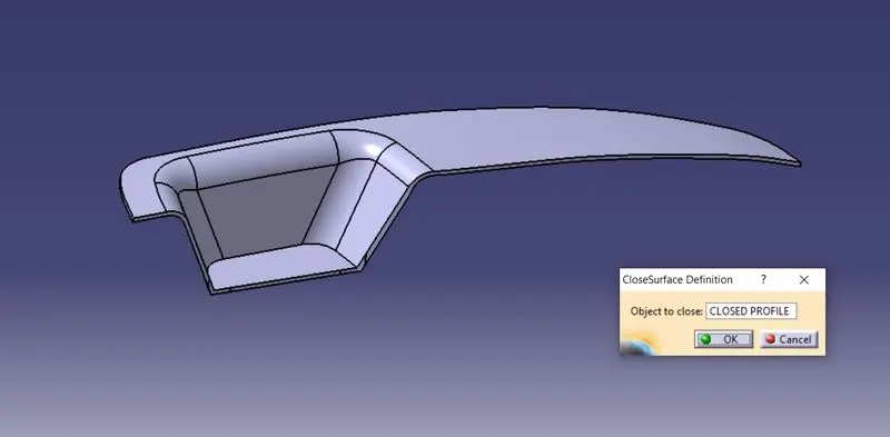
- Use of the close surface feature to make a solid body from the surface.
- To publish the tooling axis ,Class A,B and C surface.
Tooling Axis Creation:
The tooling axis is the direction of drawing a sheet metal where the finished component is easily ejected on a particular direction and axis. The tooling axis is important for removing the material when finished.
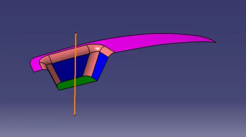
The tooling axis is created for the given class-A surface.
Creation of tooling Axis (Bisecting method):
1. Extract the base surface of the given Class- A Surface and create the center point of the Extracted surface.
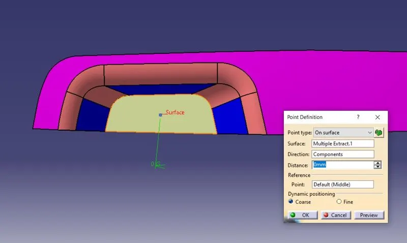
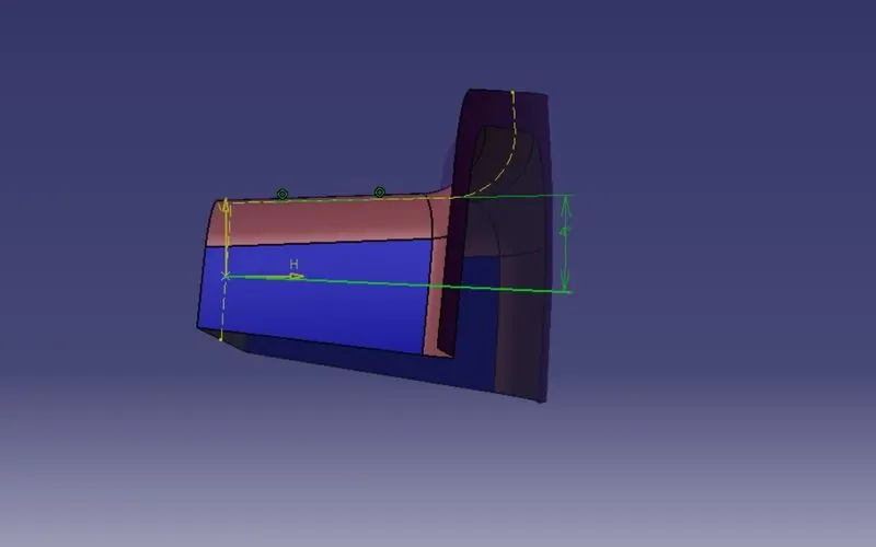
2. Then create two sketches on two planes by taking the cross section of the given surface in the particular plane.
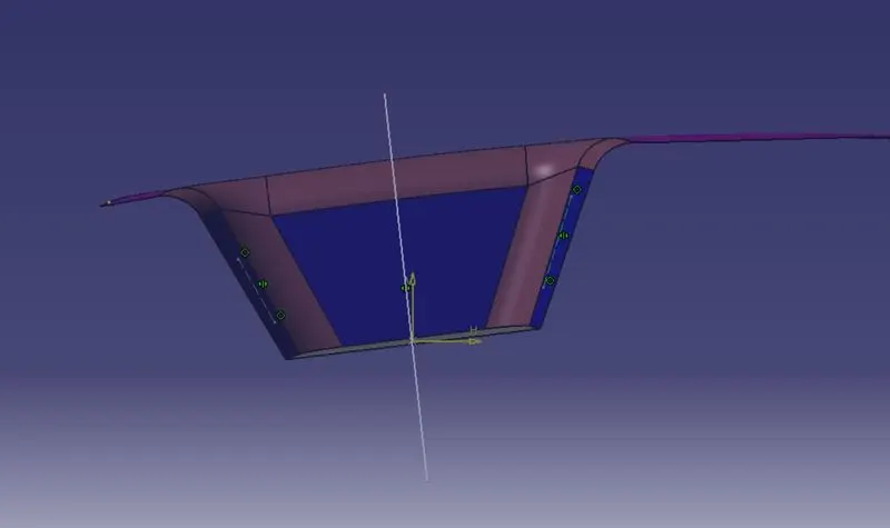
Tooling axis created from the two lines using the cross section of the surface on y plane as bisecting line.
Tooling axis created from the two lines using the cross section and also creating one with the help of cross section line of the surface on X plane as bisecting line.
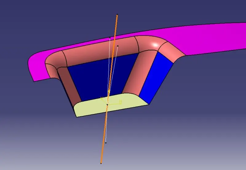
And now by creating another bisecting line using those two plane sketches is the tooling axis for this particular Class - A surface.
Creation of Class - B Surface:
Extracting the class - A surface without the fillets and then untriming and extrapolateing them to join them, and after that offset the surface to 2.5 mm thickness which forms as the Class - B surface.
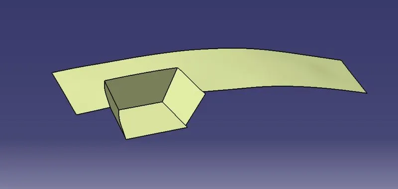
Give Fillets in required area, w.r.t Class A-Surface
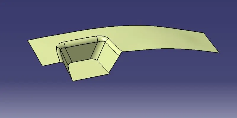
Creation of Class - C surface:
By extracting the boundary of the class - A surface, the surface required for the class - C is obtained.
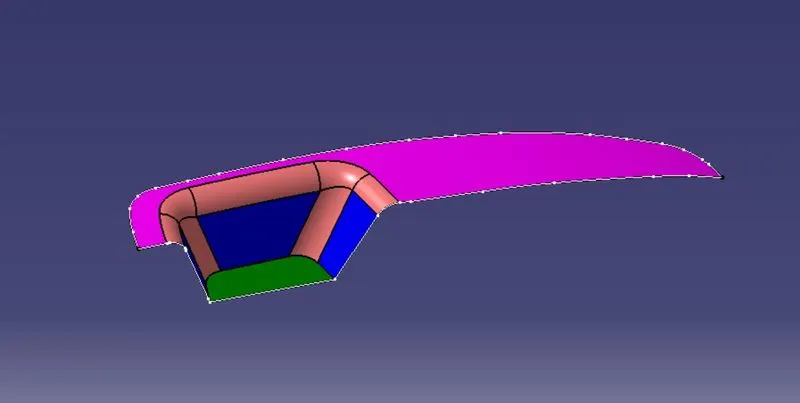
using the smooth curve option a smooth surface can be obtained by sweeping the line towards the direction of the tooling axis.
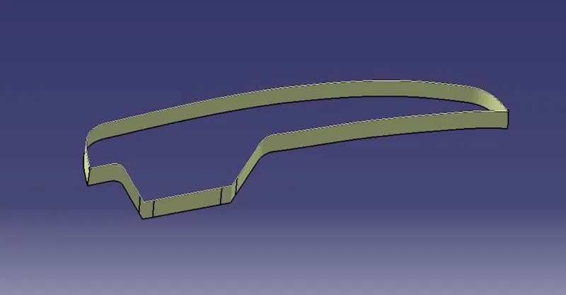
Joining & Trimming all the surfaces together,
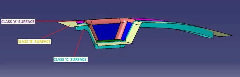
Final Output:
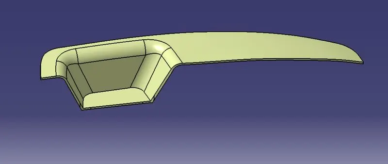
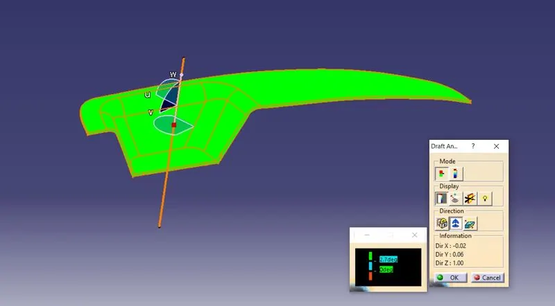
Draft Analysis on Final Surface:
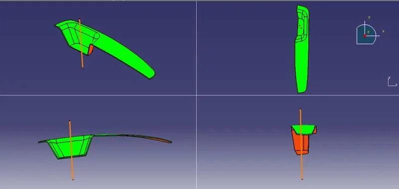
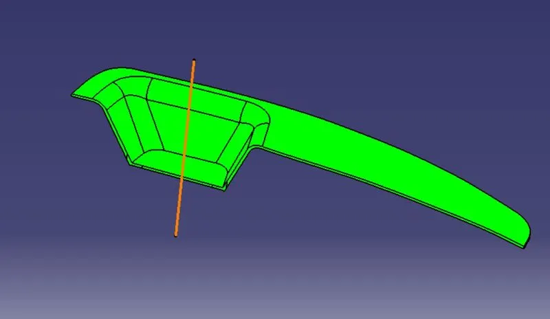
- Now drag the red coloured point on the compass to match the tooling axis which we have created.
- Click on the lock icon under the display command and a point will appear on your screen and tap the point on the surface of the Switch Bezel.
- Change the angle from 2 degrees to 3 degrees on draft analysis.2 dialogue box and on draft analysis dialogue box click ok. the below image shows the enlarged draft analysis dialouge box.
- Now go back to lock icon and click ok. and see how the object apperance. if it is in green colour we can say that the object is fine and we can proceed with that if it is showing in any other colour such as blue or red we have to modify our design.
Solid Body:
- Change to Part workbench.
- Create Body.
- Surface Base Feature – Close surface – select last join.
TREE STRUCTURE:
VIEWS OF SWITCH BEZEL AFTER PERFORMING DRAFT ANALYSIS
FRONT VIEW:
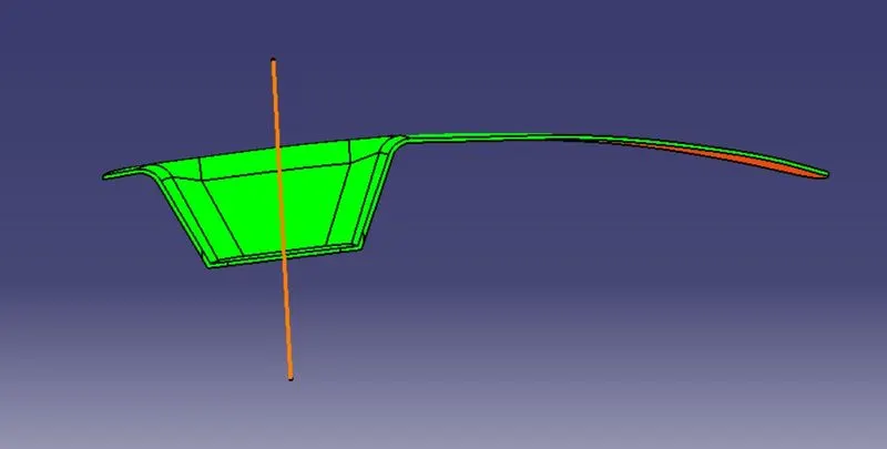
SIDE VIEW:
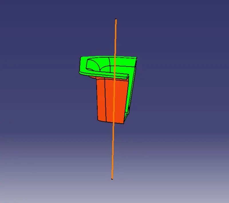
TOP VIEW:
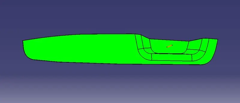
ISOMETRIC VIEW:
CONCLUSION:
And hence, Here I am concluding that the draft analysis on a Switch Bezel has been performed successfully and the report has been prepared by attaching all the images which are required.