Week 8 - Challenge 3 - Switch Bezel Design
Challenge 3 - Switch Bezel Design
DRAFT ANALYSIS:
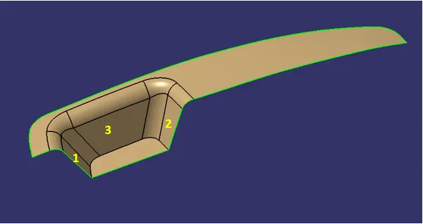
Draft analysis is done to ensure the part can be ejected from the tool after manufacturing during any forming process. In this switch bezel model the pocket area is where the problem would raise during the draft analysis. This can be avoided by creating a proper tooling axis considering the geometry of the pocket in the model. CLASS A surface of the switch bezel is shown below.
TOOLING AXIS:
From the above image the faces 1 and 2 are opposite and will clear the tooling direction. So, we need to create a tooling axis which is minimum 3deg of angle away from the face 3. Also, this tooling axis need to bisect the faces 1 and 2 with minimum 3deg so that all the faces will clear the draft analysis.
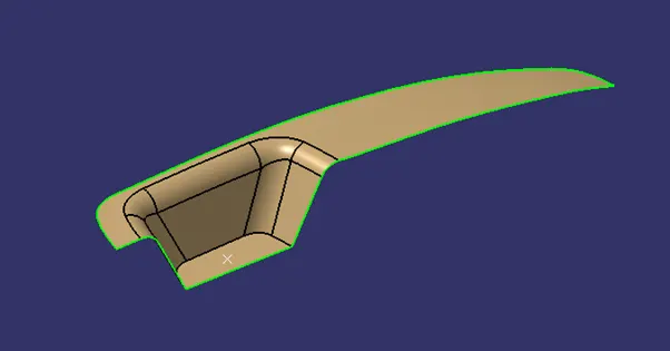
Step 1: Create a point in the middle of the base of the pocket.
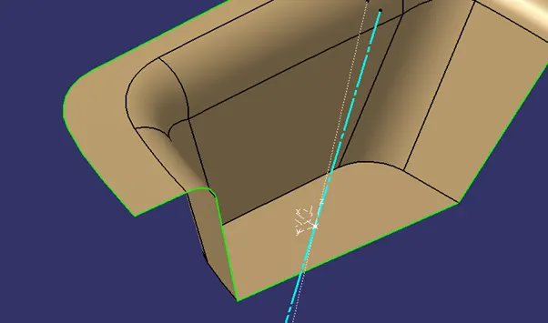
Step 2: Here I have created the line with ZX plane as a support for this line. This line is at an angle of 4deg from the normal of XY plane.
Step 3: Then the total angle between the face 3 and the line is 5.319deg as shown in the image.
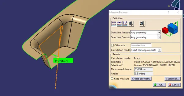
This line is used as a main tooling axis for this model.
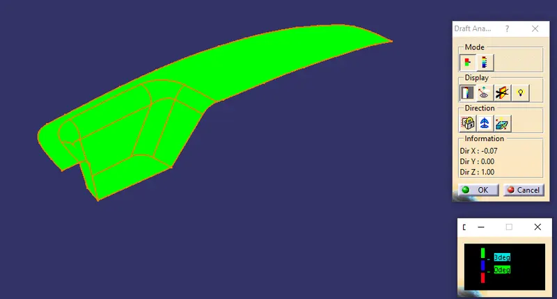
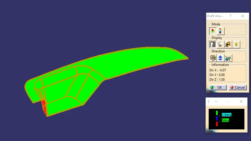
DRAFT ANALYSIS RESULTS:
Class A Surface:
Solid Model:
Views:
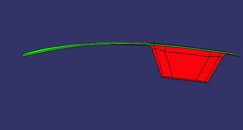
Front View:
Side View:
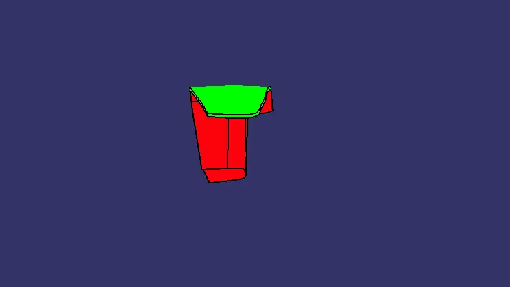
Top View:
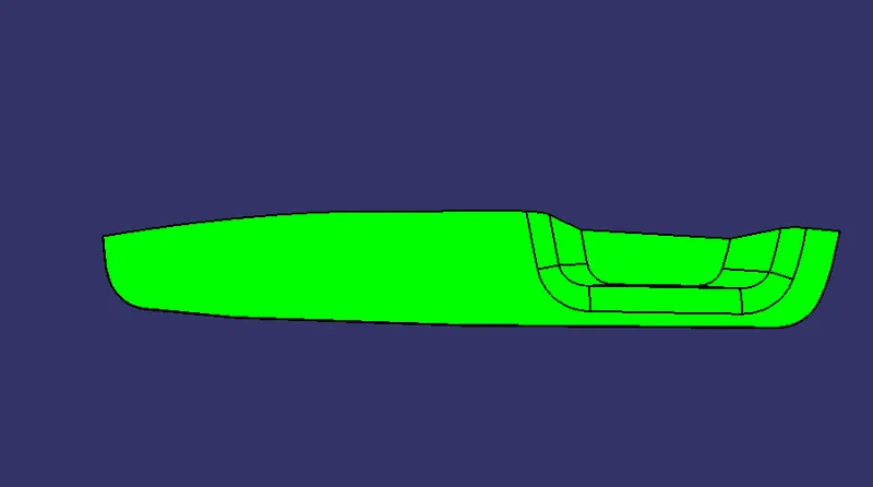
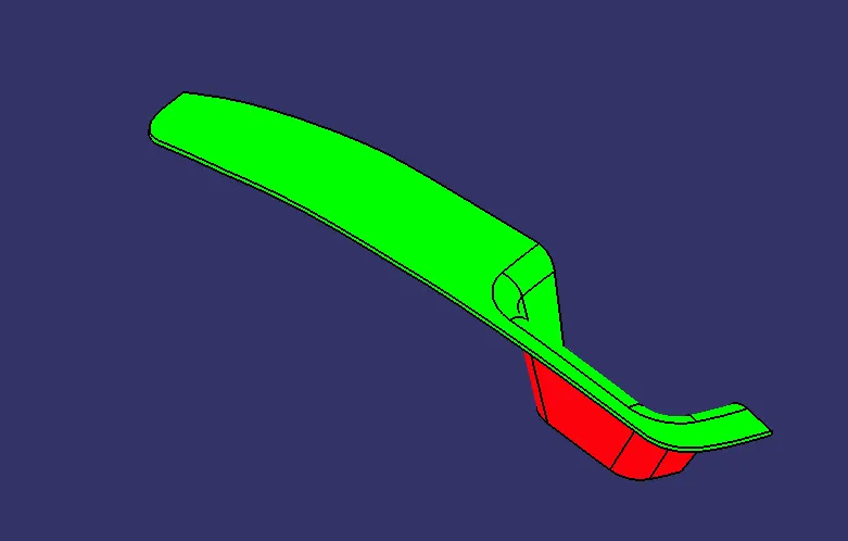
Isometric view:
CONCLUSION:
Thus the switch bezel 3D model is created using Class A, B, C surfaces with Class A surface as input using CATIA.