PREPROCESSING OF HOOD MODEL USING ANSA
PREPROCESSING OF HOOD MODEL USING ANSA
AIM:
To mesh the given hood model using Preprocessing Software (ANSA).
OBJECTIVES:
- Mid Surface Generation of given model.
- To generate the mesh for the hood model as per given quality criteria.
- Eliminating possible number of Tria Elements and Rotating Quad Elements and Avoiding Tria Elements near the Feature lines in order to create a better mesh flow.
PROCEDURE:
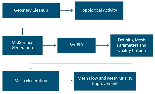
- GEOMETRY CLEANUP
Importing the model from other software to ANSA results in some geometrical deviations which needs to be cleared before proceeding to other steps. To perform geometry check Tools--> Checks--> Geometry. In General needle faces and Unchecked faces error occurred which is common while importing the model to ANSA from Modelling software. Images shown below were the geometrical errors showed up in Hood inner panel while performing Geometry Checkup.
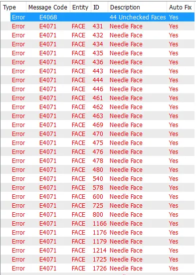
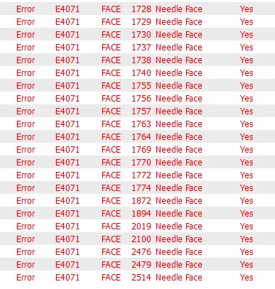
To clear these errors ANSA either we can use AUTO FIX option or Fixing the errors manually one by one.
- Auto FIX option by which ANSA detects the deviations and Heals by itself.
To Auto Fix the Errors Right Click on the error and click on Fix now the error will be gone
- To FIX the errors manually you need to find where the errors is occurring to know that Right click on the error and click Show only it will Highlight the error. To get the clear idea on the location of error we can get the neighboring faces using neighbor option or by using AND Boolean Operation.
- Needle faces and Unchecked faces can be cleared using universal delete option once the errors were highlighted.
Now our geometry is clean without any translation issues or geometrical deviations so we can proceed to topological activity.
2. TOPOLOGICAL ACTIVITY
Topology describes how the different faces and features of the geometry connected with each other.
Before proceeding to topological activity, we should save the locked views of different components of the model for better understanding.
- Separate parts can be obtained by using combination of various Boolean operations line OR, AND, NOT, INOT and Invert under Faces box.
- Views can be locked by STORE LOCK option got by dropping down the LOCK botton.
Boundary Cons of the faces and Features were called as feature lines other Cons in the Model were called as Construction Lines which were generated during modelling of the component. Construction lines can be altered as we want to get the better mesh flow. Feature lines should not be disturbed as it will result in Change in geometry however if the cons Length is less than the minimum element size it will result in element failure under such circumstances the feature line can be altered up to some extent without giving up the design feature of the part.
Image below shows how the feature line has been altered to get better mesh flow.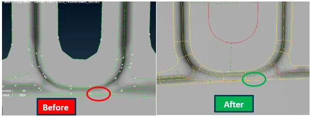
In the model above there are two feature line close to each other(<2mm) where element will fail. In order to avoid element failure one of the feature line is deleted which will not have much impact on the entire design
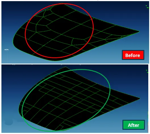
In the 1st image shown above there are many curved construction lines which will result in highier number of Tria elements therefore converting them into rectangular faces to get better mesh flow by avoiding tria elements. Its clearly shown in the 2nd image shown above.
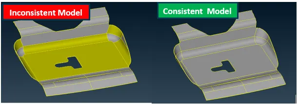
In the topological activity final step will be orienting the faces using Faces-->Orient option. Orientation in ANSA indicated by Grey or Yellow surfaces Grey surface usually acts as a positive direction and Yellow acts as a negative direction. Face is said to be inconsistent if one face having both the Grey ana Yellow Colours. FacesàOrient option will fix this issue by changing one side of the face to be yellow in colour and other side to be Grey colour. Now the model is consistent.
Images below shows the difference between
3.MIDSURFACE GENERATION:
Mid surface is the exact middle layer or surface of the component having uniform thickness over the part.For instance if the component or sheet metal having the thickness of 1mm then the surface at the 0.5mm from any of the face considered to be a midsurface.
In ANSA can generate Mid surface by two ways:
a.By Faces-->Offset option
b.By Faces-->Surface option
Lets discuss about these options:
a.Faces-->Offset:
This is manual method to generate the mid surface. Midsurface for te entire component is genetated by is generating the faces one by one by FacesàOffset command where you have to give the offset distance manually(Usually Thickness/2). In this method we have an option the keep the original face or to delete it. Once the mid surface is generated for the entire model they don’t have the associated with each other. ANSA will indiacte this by using a Single con on the boundaries of all the surfaces. To stitch all the faces with each other Face-->Topo option will be used. Select Face-->Topo--> Select the faces to want to Stitch-->Middle mouse click, Now the faces were attached with each other indiacting the double con where the two surfaces attached togather. In this method the child surface orientation may differ from the parent surface so it is advisable to perform Faces-->Orient one the Topo performed after Mid surface generation.
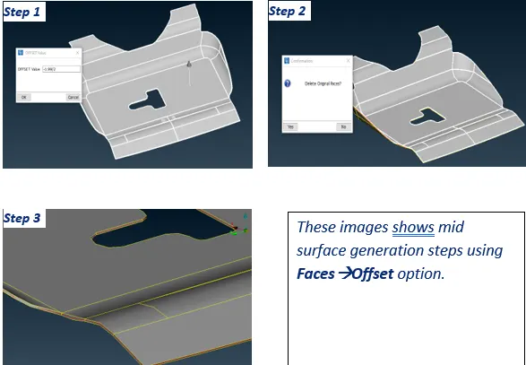
In step 1 the direction shown outside the face therefore the offset value is entered in negative value as we want to create the surface in the opposite direction. In step 3 you can see the mid surface generated in the model indicated by a single con as it is shared by only one surface.
b.Faces-->Surface:
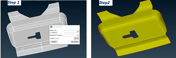
This is auto mid generation option by which Mid Surface is generated by deleting the original faces. To generate the mid surface Select Faces-->Mid.Surface now select the faces for which you want to generate the mid surface then middle mouse click now ANSA will highlight One side of the Face Red in Colour and other face in Green Colour and the faces in thickness region in Blue colour now Middle click Now the original faces will be deleted automatically leaving the Mid surface on the work space. It is mandatory that Red and Green faces shouldn’t be neighbouring surfaces
In this model Faces-->Mid.Surface is used to generate the mid surface as it saves time than FaceàOffset option as the model having highier number of faces. Possibility of errors increases in former one than the latter one.
4.SET PID:
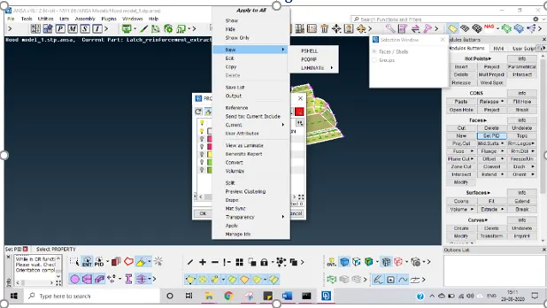
PID is property identification number. We have to assign thickness and the material to the model. To set PID Faces-->Set PID is used.Select the faces and Middle click. Now the properties window opens up. Now Right Click on the window New-->PSHELL now as shown in fig.
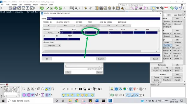
Now the PSHELL dialog box opens up where you will enter the thickness. For lock area extra support the thickness is 1.2mm.Now click OK thickness is assigned to the mid surface
To assign the material create the material using Lists-->Material or Ctrl+M. Materials Dialog box opens. To create a new material Right Click-->New--> MAT1.
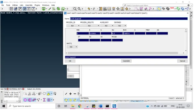
A dialog box opens as shown above Enter the properties of materials like Youngs modulus, Poisson Ratio and Density values. Click Ok now material will be added to materials list. To apply that to the our PID. Right click on the material-->Apply. Now the property help dialog box opens up click on the part’s PID now ANSA will highlight the parts in which that materials property will be applied. Click Ok. Now the material and thickness property is applied to the particular model.
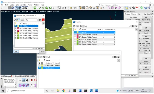
To check wheather the PID is applied to the model or not, switch to PID mode from ENT mode in Drawing styles bar. The model will change into same colour as the colour of the particular property is identified in Properties window.
5.DEFINING MESH PARAMETERS AND QUALITY CRITERIA:
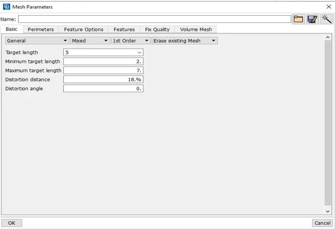
Quality of the mesh is user defined one as it varies for different applications. Quality of mesh will be defined by Mesh parameters and Quality Criteria. Mesh parameters option is available in the Utilities Bar.In that window average element Size, Minimum Element Size, Maximum Element Size and order of Mesh will be defined as shown below
Mesh Quality criteria also need to be defined from the Utilities bar.
Our quality criteria inputs for the mesh were
- Average Element Length -5 mm .
- Minimum Length -2mm
- Maximum Length -7mm
- Aspect ratio -3
- Warpage -15
- Skewness -45
- Jacobian -0.7
- Minimum Quad Angle -45
- Maximum Quad Angle -135
- Minimum Tria Angle -30
- Maximum Tria Angle -120
- Tria Percentage -15
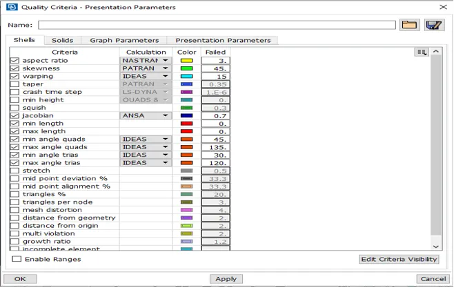
- Aspect Ratio: Ratio between Longest side and Shortest side of the element
- Warpness:Angle between normals of two planes of a quad element.This Failure is not possible in Tria Element as it has only one plane
- Min angle and Max angles were Angles included in the particular type of element.
- Jacobian: Transformation of elements to one form to another form. If the transformation can be done without any deviation then Jacobian will be 1. We should not have jacobian less than 0.6
- Skewness
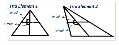
Skewness for the Element 2>Element
6.MESHING GENERATION:
Mesh generation is process of discreting the entire model into smaller elements.
In ANSA mesh generation is done by set of algorithms available for meshing.
Image shows options available for meshing. However BEST MESH is used in preprocessing of this model as it gives best mesh eliminating maximum number of elements not conforms to the quality criteria.
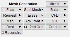
2D mesh has two types of elements:
- Quadrilateral or Quad Elements
- Triangular or tria Elements
Quadrilateral Elements:
Quad elements were the elements having four nodes. Square is considered to be an ideal quad element and the deviations were calculated in comparison with the square element. Quad elements were structured elements. They have short processing time and also have highier accuracy. Therefore Quad elements were preferred over the tria elements.
Triangular Elements:
Tria elements consists of three nodes. Equilateral Triangle is Ideal Tria element and deviations were compared with the Equilateral Tria Element. Tria element is said to be unstructured mesh. Stiffness of the Tria element is high which results in highier processing time and also have low accurate results. Therefore we should try to avoid the maximum possible number of triangular elements.
Rotating Quadrilateral Elements:
Rotating quad elements were formed when any one corner of the 5 quad elements meet at a point to form a Star like structure. Even thought they were quad elements they should be avoided in the model as they act like the tria elements.
Meshing:
Step 1:Mesh Generation-->Best selected from the Mesh Module and selecting the face that needs to be meshed.
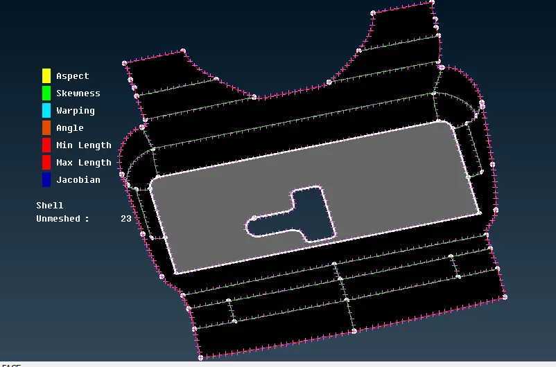
Step 2:Now Middle Clicking will generate the mesh
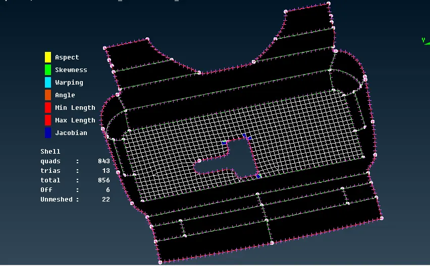
Mesh is generated for the entire model by following above said steps.
Steps followed to create the Proper Mesh:
- In this model meshing started from middle of the model and moved away from the center. So that it is easy toeliminate the traingular elements.
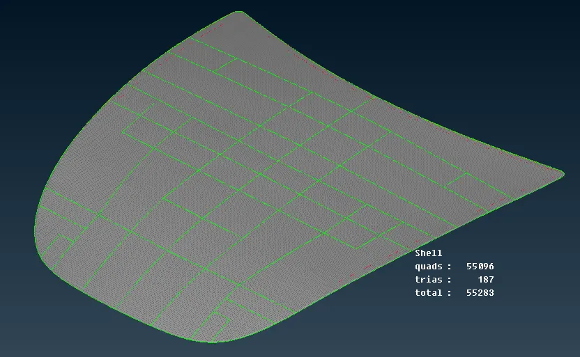
- Outer hood surface is large therefore the face is discreted such that the discreted face form a rectangle so that we can avoid maximum number of triangular elements.
- Since the Outer and Inner panel of the Hood is Symmentrical. One half of these parts were meshed and Mirrored using Transformà
7.MESH FLOW AND MESH QUALITY IMPROVEMENT:
In ANSA mesh can be generated easily but the mesh will have lot of elements will be generated such that they fail to fulfill the Mesh Quality criteria an also the mesh will have the Triangular elements which needs to be eliminated. Mesh Flow and Mesh quality improvement is the most important steps in order to achieve good mesh quality and Good Mesh Flow. To improve the mesh Quality there are many options available in ANSA. Lets discuss them in detail and how they used to achieve good mesh for the model.
- Reconstruct
- Smooth
- Split, Swap, Join
- Changing Nodal numbers
- Edge2Perimeter
- Reconstruct:
This option is similar to Mesh generation but key difference is that Mesh Generation option will generate the mesh only once but reconstuct option will try to give all possible arrangements of the mesh either by altering nodal numbers, altering the type of element or altering the element size within the allowable limit and also eliminates maximum number of errors.
Below steps to perform reconstruct option.
Step 1: Select Shell Mesh-->Reconstruct. Select the Area to reconstruct
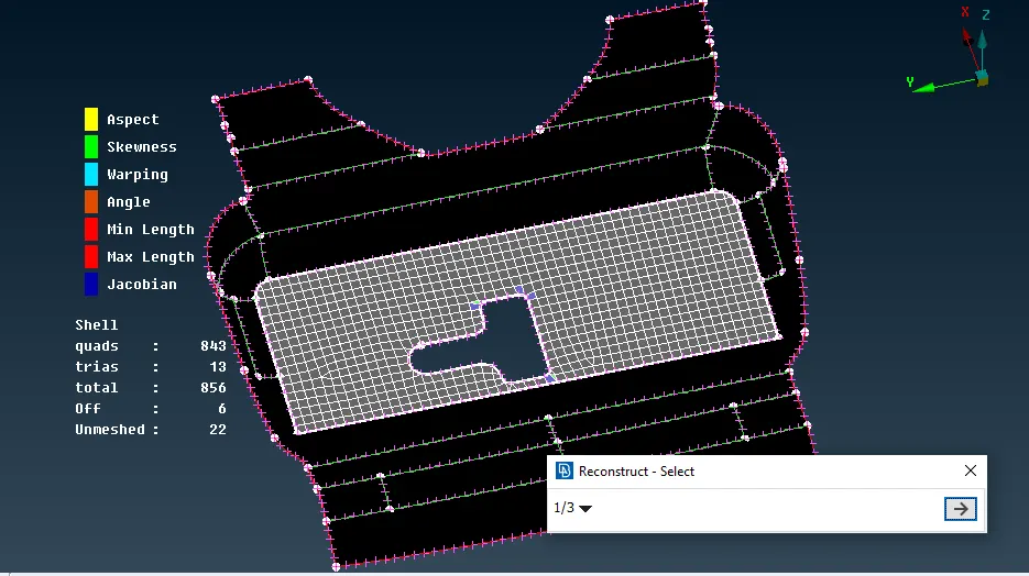
Step 2: Select the Edges and the click OK Now ANSA will show the preview of the reconstructed mesh model if the rearrangement
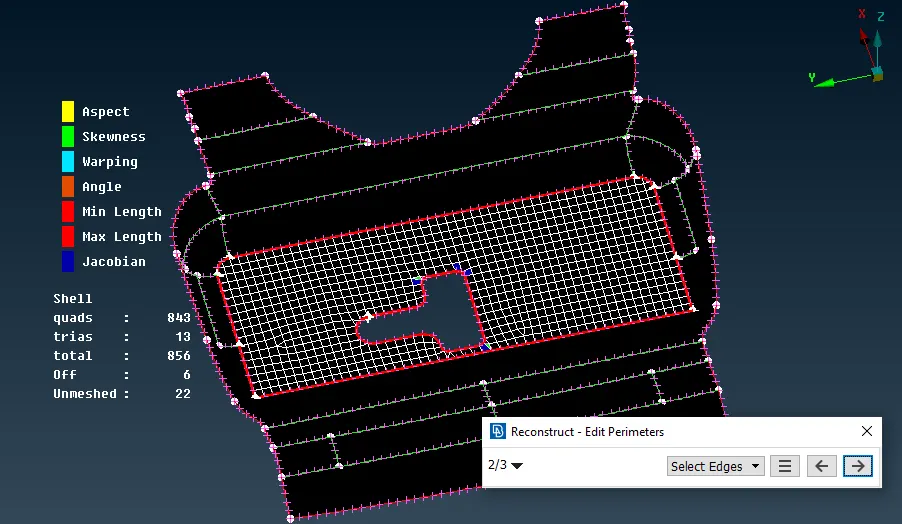
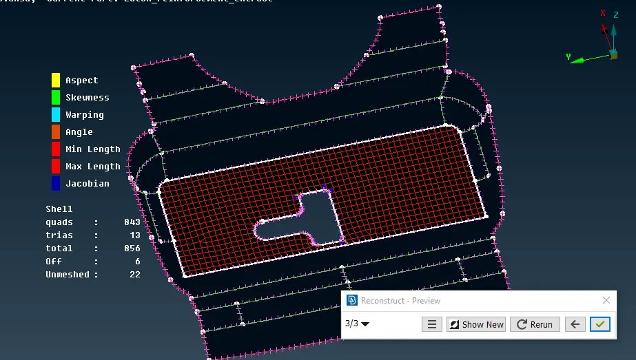
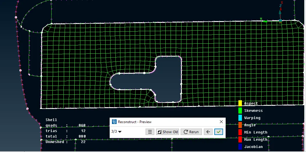
Now comparison can be made between new and old mesh and the better one can be selected.
2.Changing Nodal Numbers:
When the perimeter is having odd number of it will for a tria element which is not easy to eliminate. So, if the perimeter has odd number of nodes leaving a tria element after reconstructing it is good to change it to even number of nodes using Perimeter--> Num+/- option in mesh module. The image below shows how nodal number helps in eliminating tria elements.
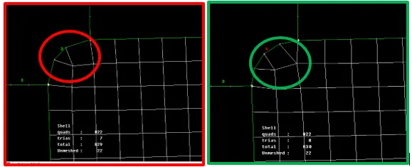
Eventhough increasing nodal number resulting two tria elements it can be eliminated by using split option.
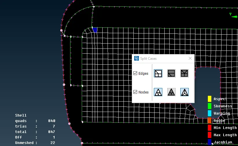
3.Split, Join Swap:
- Split option is used to split the cells into two parts.
- Join is used to Join the two Tria elements sharing same edges then the edge is removed to form a quad element using join option.
- Swap option is used only on tria elements to swap the edge from one node to another node which is available.
Above said commands can be performed in Split command itself.
Left Click acts as Split command, Right click acts as a Swap command if there is only one Tria element and Acts as a Join command if two tria Sharing a vertex.
Step 1: Split is made along the length by clicking on the element edges one by one or by selecting the element totally by drag selection. It will create a split as shown in the Image.
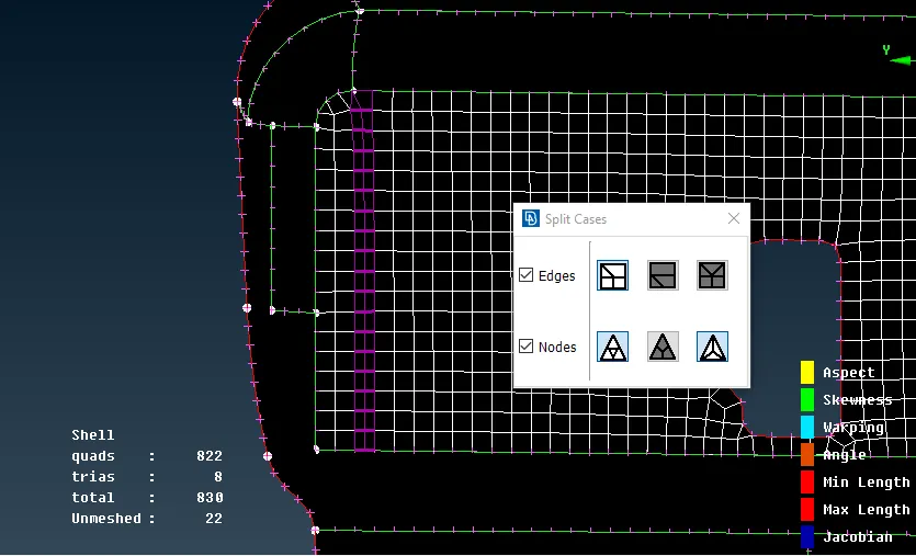
Step 2: Now when you click middle click the violet colored lines turn into Elements
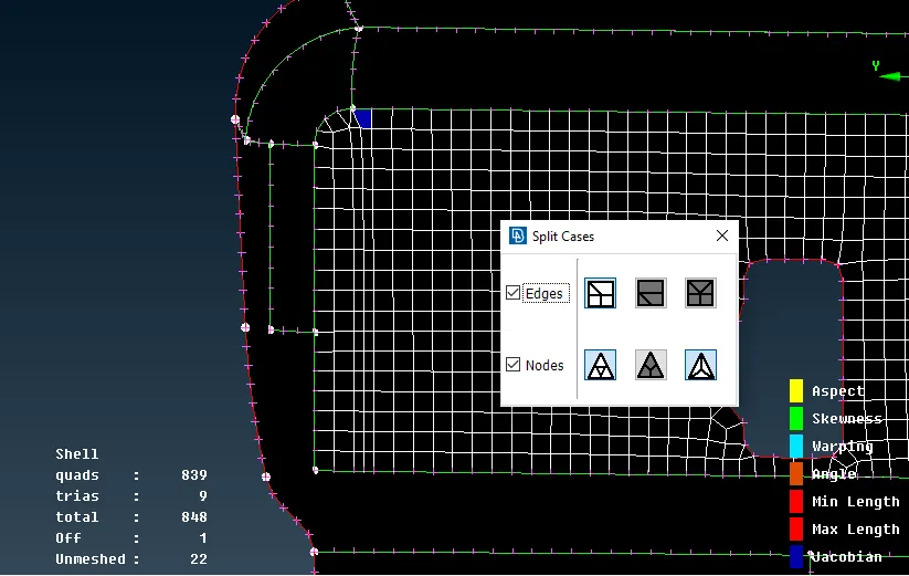
Step 3: Right click on the sides shared by two tria elements will join the trias to make a single quad element
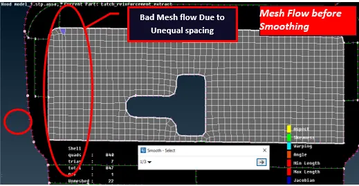
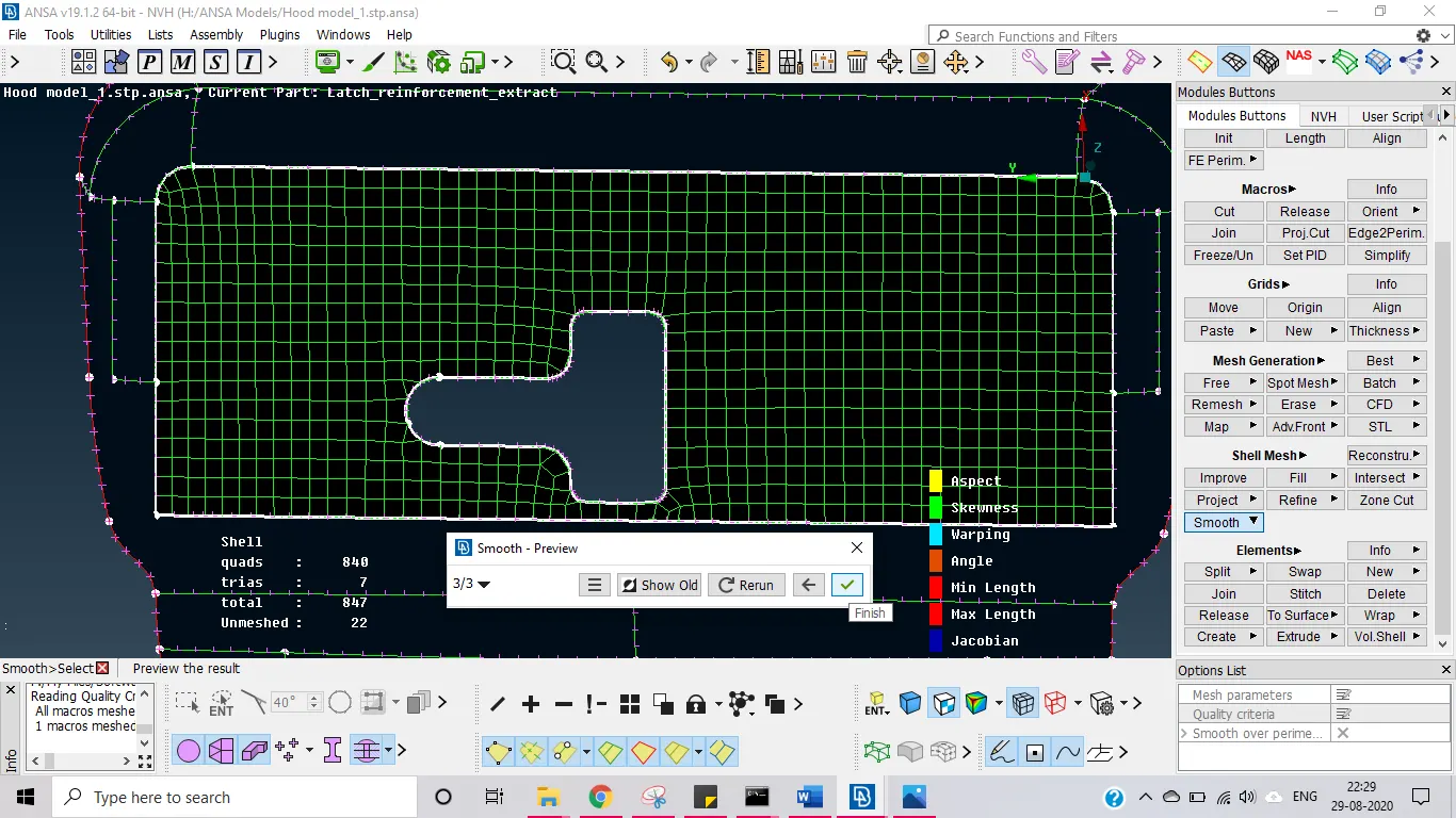
4.Smooth: This option may not be used to improve the mesh quality, but it will improve the mesh flow by trying to equi spacing the elements without changing the element arrangement as Reconstruct does
5.Edge2Perimeter:
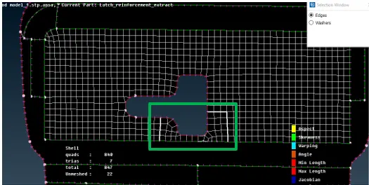
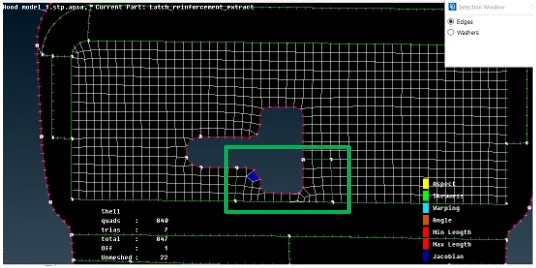
This option is used to make a cut on the meshed face parallel to the edges of the nodes without altering the existing elements arrangement. It is done by selecting option from the Perimeters tab.
Now select the nodal edges on which the cut needs to be done. Now when you middle click the cut is made on the face along the edges of the elements selected.
This option is used if you wanted to reconstruct one small area of the large surface. Image below shows how the cut is made using this option.
Step 1:Selecting the edges.
Step 2: Middle click after selecting the edges convert the edges into cuts. Shown in green coloured line.
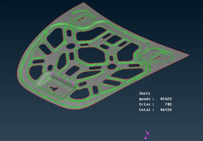
Mesh is generated and the Mesh quality and the Mesh flow is improved using the above said options for the entire model
Meshed models of different parts of the hood models is shown below:
Inner Hood Panel:
Outer Hood Panel:
Additional panel for lock mechanism:
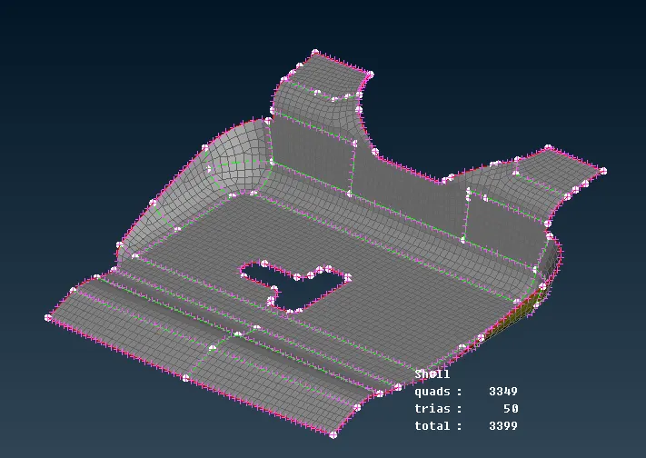
Additional support for Hinges:
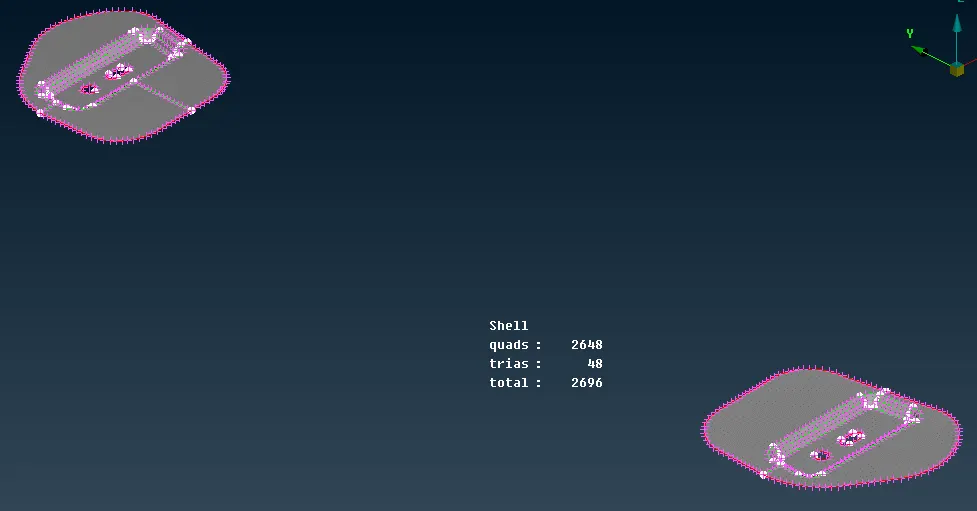
ENTIRE MESHED MODEL
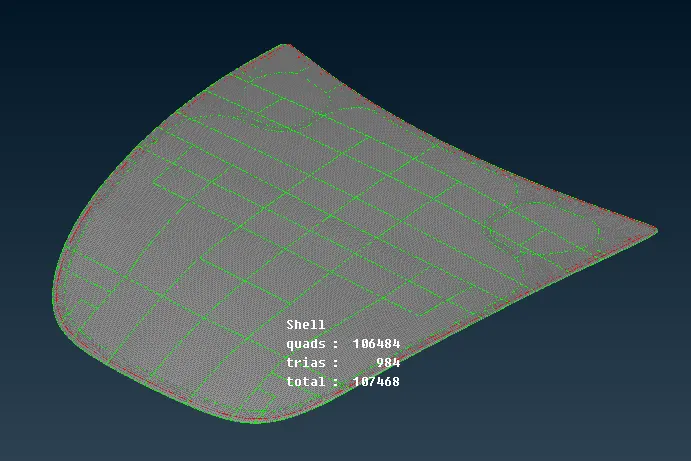
LEARNING OUTCOMES:
- Fluency in handling ANSA GUI and its commands.
- Preparing geometrical error free model for preprocessing.
- Understanding the construction lines and feature lines of the model.
- To make the topological activity without disturbing the features of the model.
- Mesh generation methodology.
- Balancing the Model’s feature and the Mesh element quality.
- Using various options to improve the Mesh quality and Mesh flow
- Syed Twaha Irfan AhmadGreat!