Radar Mast & Final Assembly of Yacht
MODELLING AND ASSEMBLING THE YACHT MODEL
INTRODUCTION:
Yacht is a sailing vehicle or power vessel commonly used for racing, Sailing, or for pleasure. There are various kinds of yachts available based of their propelling modes and the purpose which they are used. Yachts differ from boats by size and appearances. To be characterised as yacht the length of the vessel must be at least of 10 meters in length and have good aesthetics. General classification of yachts was sailing yacht, motor yacht, or gulet yacht, and then as a sports or luxury yacht. Their classification based on their size Superyachts are typically 24 meters (78 feet) and above. Mega yachts are typically over 80 meters (260 feet). Further they were classified based on their appearance and functions such as with flybridge, sedan, pilot house, and sportfish yachts, for example.
OBJECTIVES:
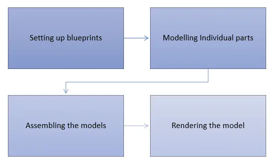
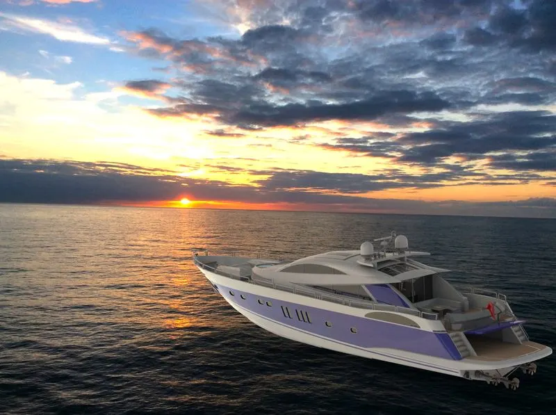
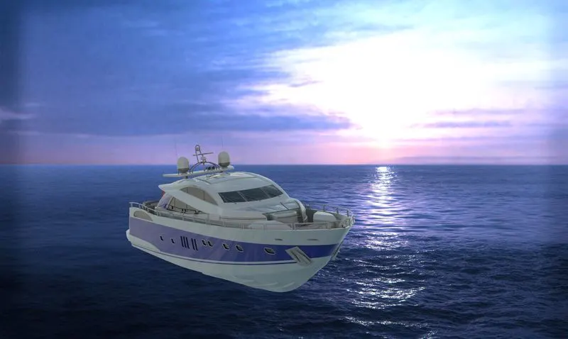
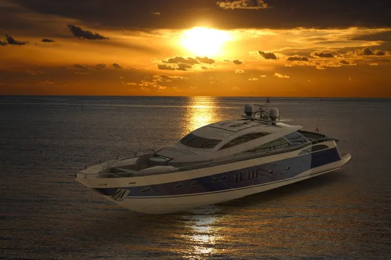
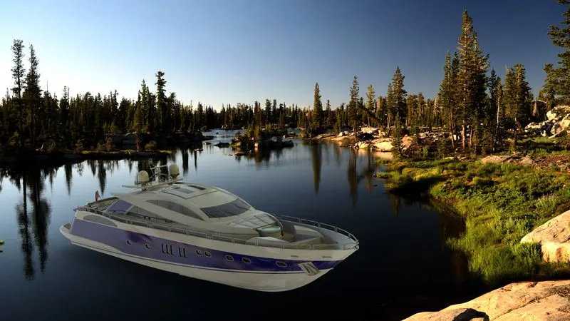
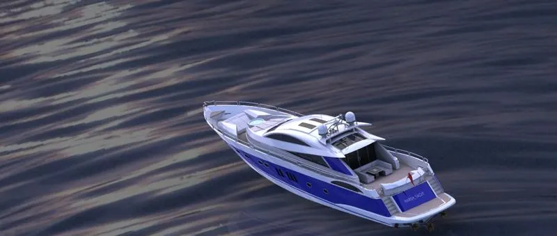
In this project we will be modelling parts of the yacht using the concept sketch. All the parts were modelled in Solidworks part modelling workbench and assemble them in Solidworks assembly workbench. To make the yacht more realistic we will be adding the decals and render it in a real time HDR environment using Solidworks visualize.
DESIGN METHODOLOGY:
MODELLING:
Propeller:
Propeller is the driving unit which helps to move the yacht. It can be compared with wheels in the bikes and cars. The propeller is generally driven by engine through the transmission system.
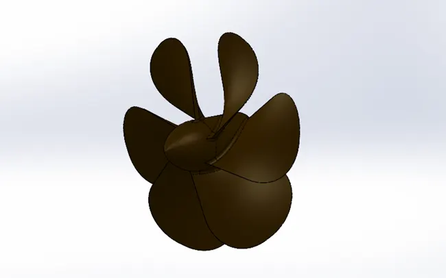
The base of the propeller is first modelled by using Revolve feature. One of the blades is created by Loft feature and to make it much more realistic it is Filleted around the corners. Then other blades were created by Circular-Pattern feature. A hole is made on the back side of the base of the propeller using Cut-Extrude to create a hole for fixing it with propelling shaft.
Radar:
Radar is a device which helps sailors in navigation. It also helps to detect other ships, boats, and poor weather which can affect the visibility of the sailors so that they can be able to avoid any major accidents. It detects the objects with the help of a radio signal.
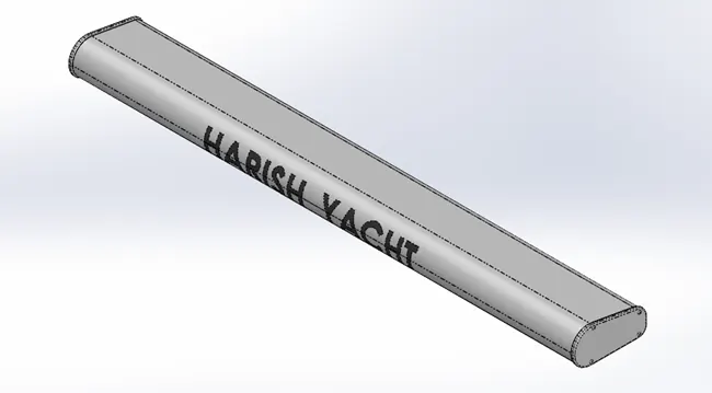
This model is created Extrude command. Fillets done to avoid the sharp edges and also to make a desired shape around the model. Sides of the main block is created by using Convert-Entities feature and extruding them from the base of the main frame. Screws were Extruded and Filleted to make ball shaped head and Hexagon hole for the Fastening is created using Cut-Extrude feature.
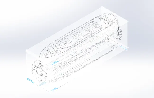
Before proceeding to modelling of the hull we have to set up the blueprint of the all the views of the yacht model on their corresponding planes. Below image shows the blueprint setup of the models in the sketches using the Sketch Picture command when inside a sketch.
Hull:
Hull in general terms refers to many things which acts as an outer covering. Outer layer of Seeds, air crafts, ships, boats were usually called as Hull. Hull in all the watercrafts were provided with watertight body to provide the buoyancy for the ships to float. It also carries the engines and propellers to propel the craft typically submerged under water always in some cases they have provisions to take out the propellers out of the water for any maintenance purposes. There are two flat plates located on both sides of the hull near the propellers to prevent the roll movement of the yacht. They also carry the anchors to prevent the movement of the craft with waves. Further the deck may contain some amenities to relax based on the personal choices.
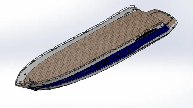
In this model Project Curve becomes a handy feature to create surface lofts. Two base surfaces of the hull are created using Surface Loft feature. Surface-Trim feature is used to cut the base shell to create a slant edge to create a Surface Loft near the steps area. Then the top and the inner side of the surface were covered using the Surface fill option and make them as solid. Boat kind of shell is formed from the solid using Shell feature with thickness of 120mm. Now we have full shell but a solid to act as a deck surface which need to be created Extrude feature. The base which is extended from the hull is created using the Extrude feature then it is trimmed and filleted to get the final shape using Cut Extrude, Fillet and Chamfer features. Then windows are created using Cut Extrude feature and sharp corners were Filleted. Now a plane is created normal to edge of window created and a circle is drawn and swept along that sketch using Sweep feature. Now the window is created using Cut Extrude option in Arc shaped window and the walls near the steps. Now space for the steps is created on the hull solid at back side using the Extrude Cut feature. Steps were created using Extrude feature using the Sketch as input. Now the features on the Deck surface were create using commands like Extrude, Extrude-Cut, Fillets, Linear Pattern, Helix, and 3D Sketches. Handrails and the grilles for the windows near steps and arc shaped windows were created using the Swept Boss feature. Now railings references were sketched in Mid Plane and the edge of the outer surface is offset for 60mm in a different sketch. Now both of the sketches were converted into a single curve using Projected Curve feature. Then a plane is created at one end of the projected curve and Circle of 25 mm is made and pierced with the curve. Railing is created using Swept Boss feature. Now the stabilizers and propeller shafts were created using Extrude, revolve features and further to get realistic appearance Chamfer and Fillets were added to the model. Now the space for the garage is created and the cut block is saved in a different file to model the garage door from it. Once the model is created the deck surface is extracted using Surface Offset option with 0mm offset to use them in a creating Superstructure, Front, Middle and Rear Seats. Then the model is mirrored about the Mid plane and the surfaces, solids were knitted and merged together to form a single solid.
Garage Door:
It is the covering unit for the garage.
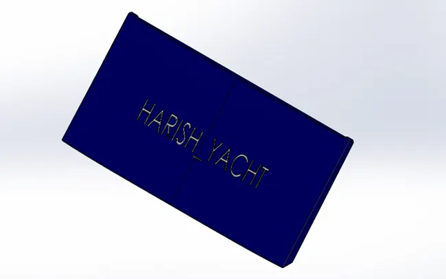
The garage door is created from the block which we have saved when we are modelling the Hull. The block is converted as a door by trimming the block with cut-Extrude feature. Inner side, top side and the right side of the door is made into a Shell feature with thickness of 50mm. All the sharp edges were avoided using Fillet feature. Hole on the side of the door is created by Cut Extrude option. The body is Mirrored about the Mid Plane, and the solids were merged. The text is entered in a sketch and projected on the door using Cut-Extrude command.
Front Seat:
Front seat is one of the relaxing spots which is placed on the deck surface.
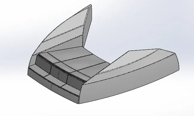
Outer surface of the side body is created by Surface Swept feature and the inner surfaces were created by surface extrude option. Then these two surfaces were trimmed together, and the top surface is covered using Surface Fill feature. Middle part is created using Revolve feature up to the mid plane. Then the seats were created using Revolve feature then all the bodies were mirrored, and their edges were blended using the Fillets feature. Then the top surfaces were made into convex surface to give realistic look using Dome feature.
Middle Seat:
It is spot for dine or to relax on the yacht.
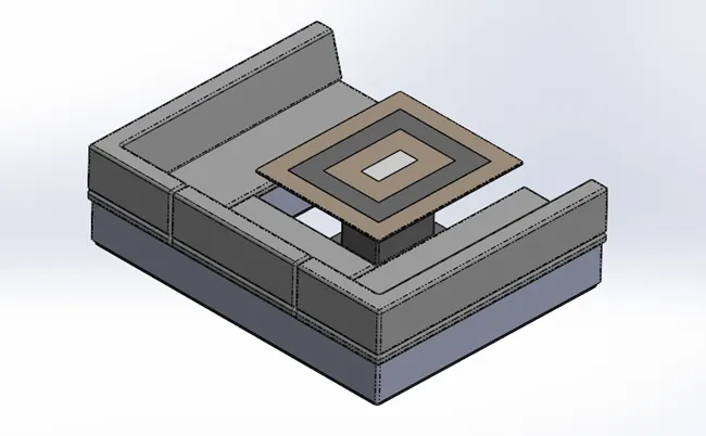
This model is created simply by Extruding the sketch made on the deck surface. Then the base cushion faces were Extruded. Table is created by Extruded from the base of the deck.
Rear Seat:
Rear seat is placed near the middle seat at the edge of the deck surface on the rear side.
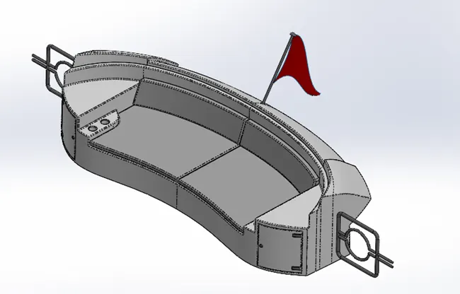
Back side of the seat surface is created using Surface sweep feature along the curved shape guide curve. Then side end surfaces at the back side is created using the Surface offset feature. Then these two surfaces were trimmed using a straight line. The outer surfaces were extended using a Ruled surface command and the outer side of the surface is trimmed off with a straight line using Trim surface command. Inside surface of these two surfaces were joined in a same continuity and a step is formed on the outer sides of the two surfaces using Surface Loft, Surface Sweep, Surface Trim, and they were joined using Surface Knit feature. Then all the other side were also extended and made as a solid using the above said commands. Seating base is created by Extruding the sketch from the Deck surface and the space for storage is Extruded from the seat surface. On the front side of the rear seat the door kind of look is created for the storage is created using a Cut- Extrude feature. Hinges and the handle for the door is created using Extrude Boss feature. Solid for the cup holders were made by Boss-Extrude command and Holes were made on the solid to act as cup holders using Cut-Extrude feature. Then cushion surfaces were made by offsetting the base surface using the Surface Offset command. Side grilles were created using a Swept Boss feature. Then all the solids were mirrored about the mid plane and the solids were merged. Flag is created using Surface Loft feature with 3D curves as input.
Superstructure:
It is an extended structure built over the existing structure. The size of the superstructure has great influence on the mobility of the vessel. They were designed in such a way that they hinder the speed and mobility in the least amount. The radar, signal transmitters and other communication devices were usually placed on the superstructure as it is the highest point of the superstructure.
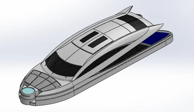
The base of the superstructure is created by Surface-Extrude command using the sketch made of Lines and Splines using the Blueprint of the model. Further the surfaces were made using Surface-Loft command with the 3D curves and the Projected Curves and input. Water jacuzzi is created using Revolve command and the water surface is created using the Surface Extrude command. Handrails were created using Swept boss command. Steps were created using the Extrude command. Dome feature is used to give the realistic look to the relaxing spots. Then all the bodies were mirrored about the mid plane. One of the top surfaces on the rear side is Extracted using Surface offset command to use it for creating the radar mast.
Radar Mast:
Radar mast is the base where the radar is mounted. The mast also consists of supporting devices for the radar device. They may also contain waterproof enclosures for some devices. They send the details of the signals received to the sailor to know about the land, bad weather or any other ships nearby.
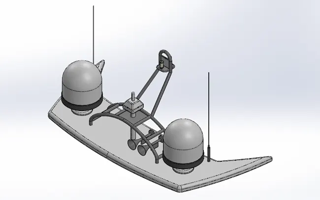
Base of the radar mast is created using Extrude command. The enclosures were created using Revolve command. The ladder like structure is created using the Swept Boss feature. The antennas were created using Extrude command from the radar base. Once all the bodies were created, they were mirrored about the mid plane. The horn outer surface is created using the Revolve command which makes it as solid, and the horn is made as shell using the Shell feature applied to the front face of the Horn.
YACHT ASSEMBLY:
During assembly in the PLM software the assembly is done in two ways
Top-down approach
Bottom-up approach
Top-Down approach:
Top-down approach is used when we design the custom parts. All the parts were designed in the assembly environment to get the references from the parent parts. The parts will get updated automatically based on the parent parts and will reflect in the assembly itself.
Bottom-Up approach:
Bottom-up approach is used when we are using any of the standard part available in the market. If we use any shaft of standard size, we will be designing the hole feature in the separate part as we are not going to alter the size of the hole. Similarly, all the parts which we know that the size of the features of the part were not going to change during the entire design process we can go for Bottom-up approach where all the parts were modelled separately and assembled in a separate file.
Yacht Assembly:
As we know the dimensions for the model is predetermined it is modelled using Bottom-up approach.
A new assembly file is opened, and the Hull is imported into the assembly workspace and placed in its default location.
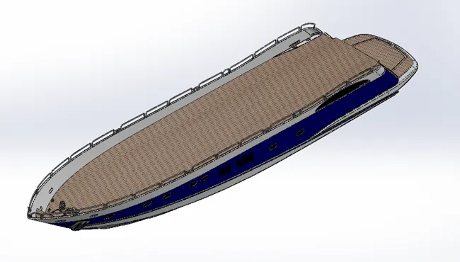
Front seat, Middle seat, Superstructure, and radar mast were imported and placed in their default locations.
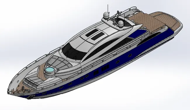
Rear seat is imported into the model it is coincided with the deck surface and placed at a distance of 50mm from the rear edge of the deck surface.
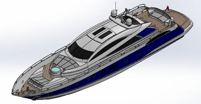
Garage door is imported into the model and concentric mate is provided between the hole in the garage door and the projection in the hull model. To ensure that it is place in the middle of the model width mate is applied between the face of the projection and the face of the hole.
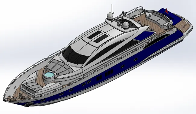
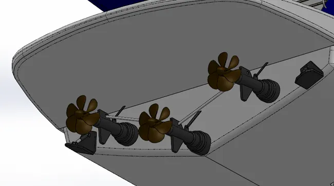
Propellers were attached to the driving shafts using the concentric mate between the hole on propellers and the outer face of the shaft then the face inside the hole and the face at the end of the shaft were made to coincide. Then the mid plane of the propeller and the mid plane of the assembly were made parallel.
Radar is imported and placed on the shaft using the concentric mate and face of the shaft and the hole is coincided to prevent the Z axis movement. The front plane of the radar and the front plane of the assembly model is made parallel to arrest the movement completely.
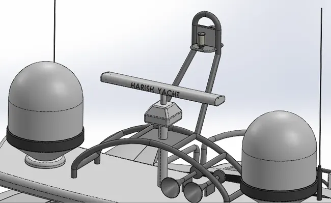
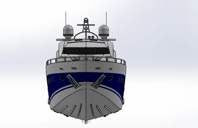
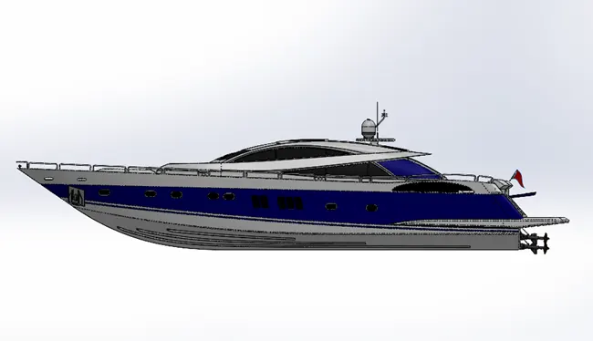
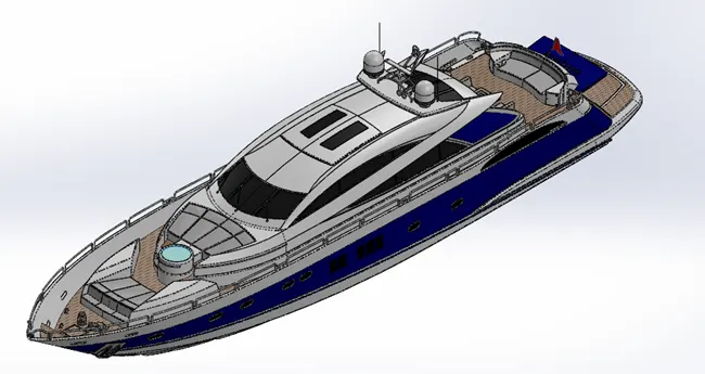
Now we have the complete assembly of the yacht model.
Front View:
Side View:
Isometric View:
REAL TIME RENDERS:
CONCLUSION:
Thus we have modelled and rendered the a luxury yacht.