DESIGN OF ROOF USING NX CAD
ROOF DESIGN USING NX CAD
INTRODUCTION:
Initially the cars were manufactured without the roofs. Later to protect the passengers from the sun shelter is attached though they can protect from the sun they were not effective against the strong wind and rain to overcome this problem the cars with detachable roofs were introduced. These can be attached or removed as user wish and often, they were stored in the car’s boot. From mid-19th century the engines were became more powerful so parallelly the safety also needs to be improved to save the passengers inside in case of any accident. So, the roofs became important during the roll over conditions.
DESIGN CONSIDERATIONS:
- Heat Distortion.
- Snow load Criteria.
- Roof Crush Test.
Heat Distortion:
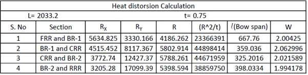
The temperature for which the roof withstands the specific load. If any NG occurs while calculating, then the roof bow positions need to be changed and the process need to be repeated until the condition satisfies.
W=[1.73 x 10^ (-3) x L] + [1.85 x 10^(-8) x (R^2)/t] + [ 1.10x10^(-3) x l] - 2.68
Judgement Condition: OK< 2.7> 3.1
where,
L = Roof Length in X-Direction[mm] (Roof dimension in 0-Y)
R = Roof curvature
R = 2(Rx*Ry)/(Rx+Ry)
Rx = X curvature
Ry = Y curvature
t = Roof plate thickness [mm]
l = Bow Roof Span [mm]
Snow Load criteria:
In European countries where the snow fall will be high. Huge amount of snow will deposit on the roof so to withstand the load on the roof snow load criteria. The criteria will be the roof must undergo elastic deformation only. The roof should return back to its original state when the load is removed.
Qr = [Iy x t2] / [α x s x [(Rx + Ry)/2]2 x 10-8]
Where
α = My x Lx2 x 10-12 , My = Y(Ly-Y)
Judgement condition = Qr ≥ 3.1
250 ≤ s ≤ 380
t = Roof plate thickness [mm]
Ly = Distance between the front and rear roof Rails on the Vehicle along with 0Y[mm]
Length of Roof panel with the center point between Roof rail Front /Rear as the reference point of the front and the rear.
Lx = Distance between the Left and Right end of the roof on the Roof BOW [mm]
Width of the roof panel exposed on the surface.
Y = Distance front Front Roof Rail to Roof BOW[mm]
s = Distance for which Roof BOW bears divided load [mm]
s = L1/2 + L2/2
Iy = Geometrical moment of inertia of Roof BOW (Y cross-section )[mm4]
Rx = Lateral direction curvature radius of roof panel Y cross-section on Roof BOW [mm]
Roof panel curvature Radius of the Length Lx in Front view
Ry = Longitudinal Direction curvature radius of the Roof panel X cross-section on Roof BOW [mm]
Roof panel X curvature radius of length s in Side view

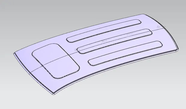
Since the sections FRR and BR-1 and CRR and BR-2 failed for snow load criteria so we can improve the strength of the roof by introducing the emboss on the roof as shown below.
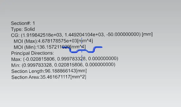
MOMENT OF INERTIA OF THE SECTIONS:
i)Rear Roor Rail:
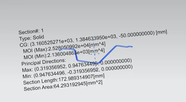
ii)Bow Roof 2:
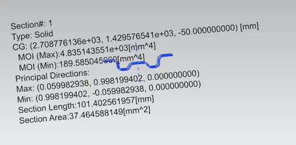
iii)Centre Roof Rail:
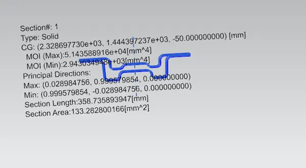
iv)Bow Roof 1:
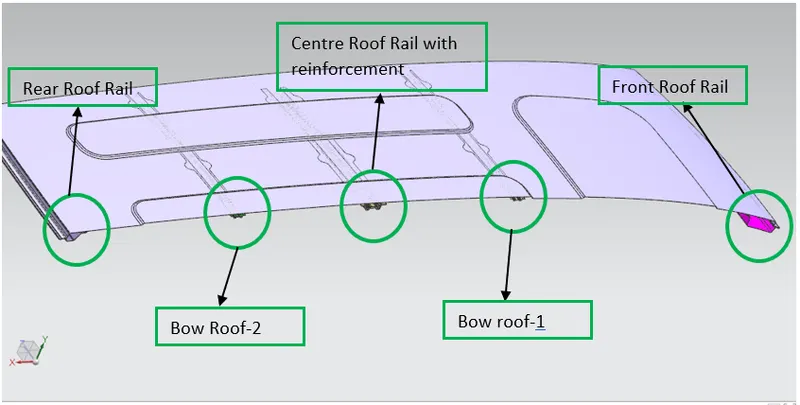
Sectional View:
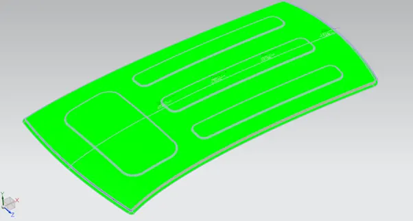
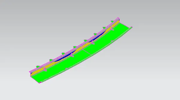
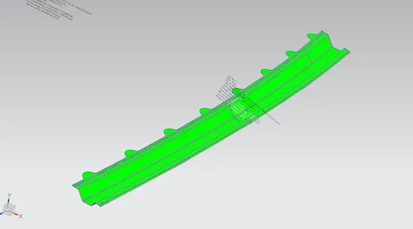
Draft analysis:
i)Roof:
ii)Front Roof Rail:
iii)Rear Roof Rail:
CONCLUSION:
Thus the Roof reinforcements were designed from the skin data received and draft analysis, Heat distortion and Snow load conditions were verified.