CV JOINT AND QUICK RETURN MECHANISM IN ASSEMBLY WORKBENCH
DESIGN AND ASSEMBLING CV JOINT AND QUICK RETURN MECHANISM IN CATIA
CV JOINT:
CV joint is a is coupling which is used to transmit power from the transmission to the wheels at constant-velocity. The joints were made in such a way that they can accommodate the up and down movement of the wheels due to the pits and bumps on the road these joints are called as Ball type CV joints and to and fro motion at the transmission area to adjust the length of the shaft due the up and down movement of the wheel and this joint is called as Tripod joint.
QUICK RETURN MECHANISM:
Quick return mechanism is used where the rotary inputs is provided to get the reciprocating motion as the output. They were achieved by constraining the relative motion of the links as per the requirement. Quick return mechanism enables the quicker retraction of the reciprocating link or the output link which abruptly reduces the idle time of the machine and improves the output. There are three types of quick return mechanism.
- Hydraulic Drive.
- Crank and Slotted lever mechanism.
- Whitworth Quick return mechanism.
CATIA MODEL OF QUICK RETURN MECHANISM:
To create the models, we are provided with the 2D drawings of the parts of the assembly.
Base:
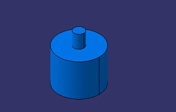
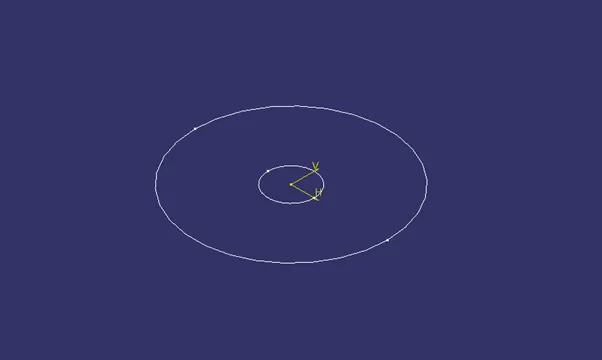
The image shows the base of the Quick return mechanism assembly, or it is the driver of the mechanism. The image below shows the sketch of the base.
Slotted Lever:
This part provides the constrained motions to the sliders which are attached to it.
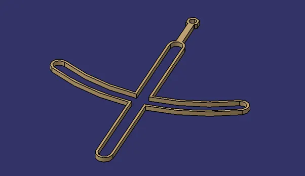
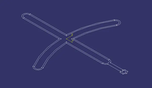
The sketch of the slotted lever is shown below.
Swinging Arm:
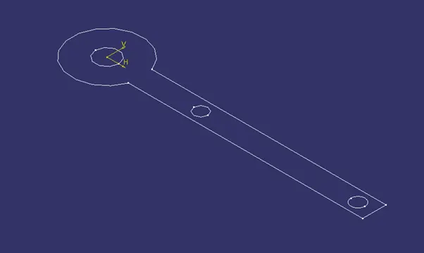
It is the part which provides the output by following the sliders which follows the path of the slotted lever.
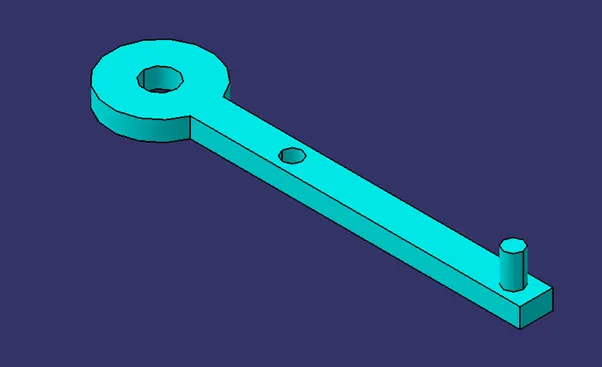
The image below shows the sketch of the swinging arm.
Slider:
Slider is the part moves along the slotted lever and provides its output to the swinging arm.
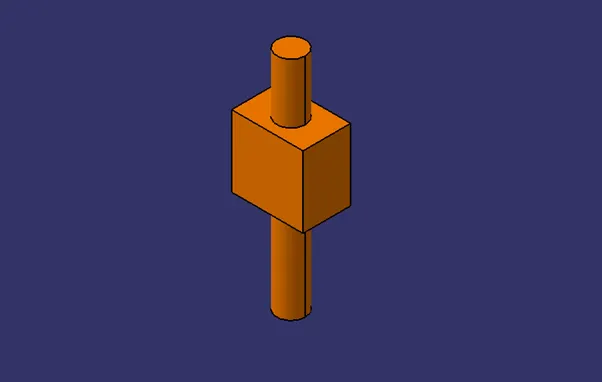
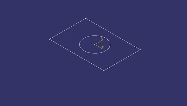
The image below shows the sketch of the slider.
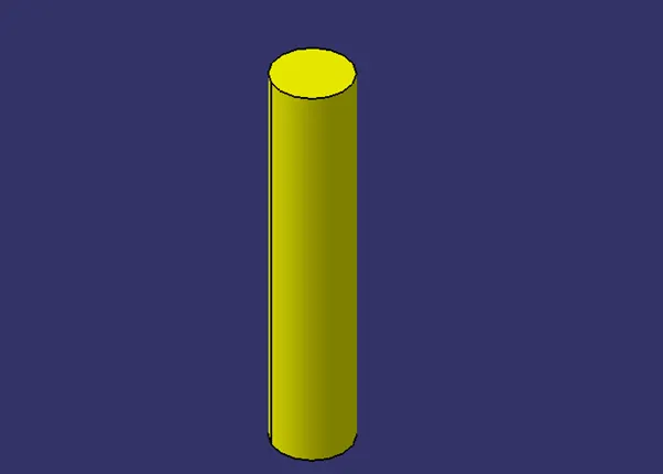
Cylinder Slider:
This slider sider along the arc slot on the slotted lever and it is connected to the swinging arm to provide the output.
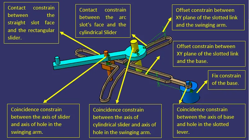
ASSEMBLY CONSTRAINS OF THE QUICK RETURM MECHANISM PARTS:
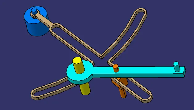
ASSEMBLY ISOMETRIC VIEW:
CV JOINT ASSEMBLY:
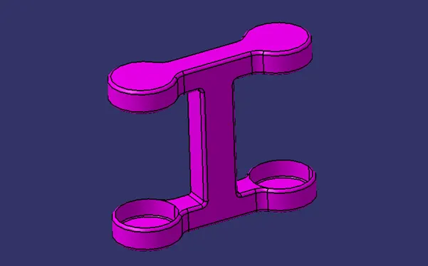
Base:
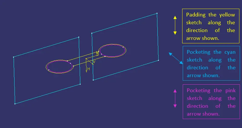
The image below shows the 3D model of the base of the CV joint.
The image below shows the sketch of the base.
Intermediate Member:
The image below shows the intermediate member of the CV joint assembly.
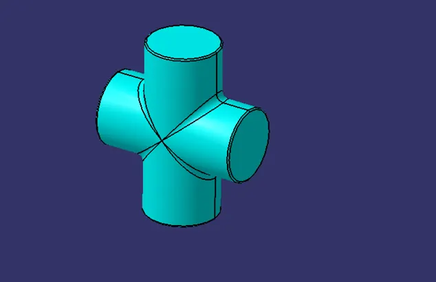
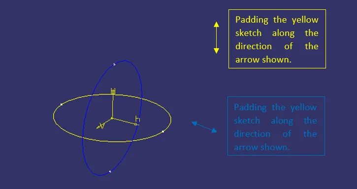
The image below shows the sketch of the intermediate member.
Driving/Driven Component:
The image below shows the 3D model of the driving/driven member of the assembly.
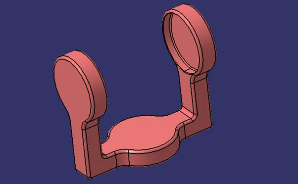
The image below shows the sketch of the driving/driven member.
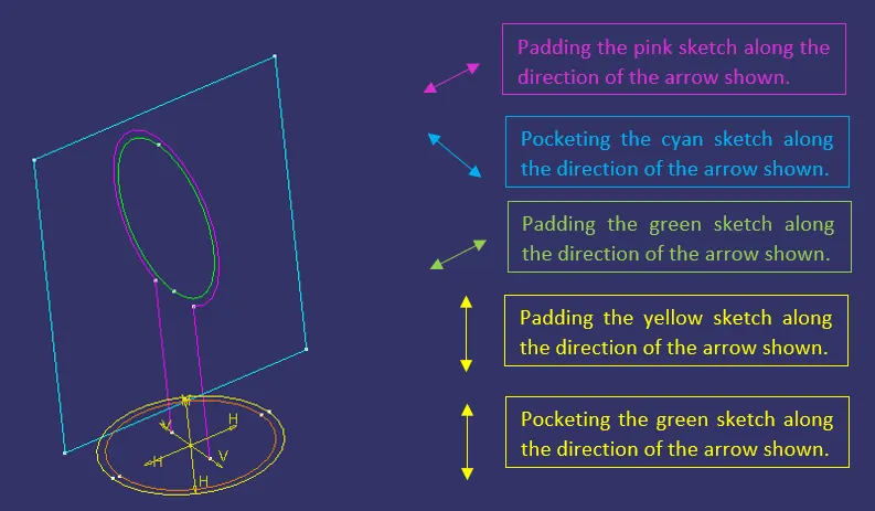
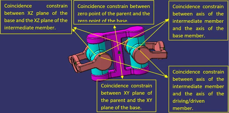
CONSTRAINS OF THE ASSEMBLY:
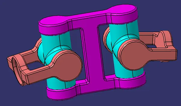
CV JOINT ASSEMBLY ISOMETRIC VIEW:
CONCLUSION:
Thus, the CV joint and Quick return mechanism parts were modelled in part workbench and assembled in assembly workbench in CATIA.