Week 8 - Challenge 2 - Base Bracket Design
BASE BRACKET
OBJECTIVE:
To create the Base Bracket Plastic component through the given Class-A surface.The tooling axis for the given Class-A Surface should be created meeting the requirements of the draft angle and at the end perform the Draft analysis on the model.
Tooling axis creation:
First step is tio insert the given class A surface.
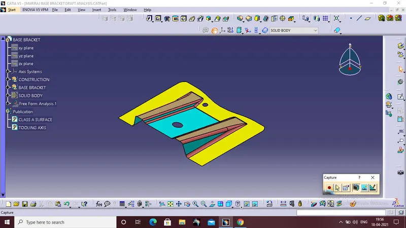
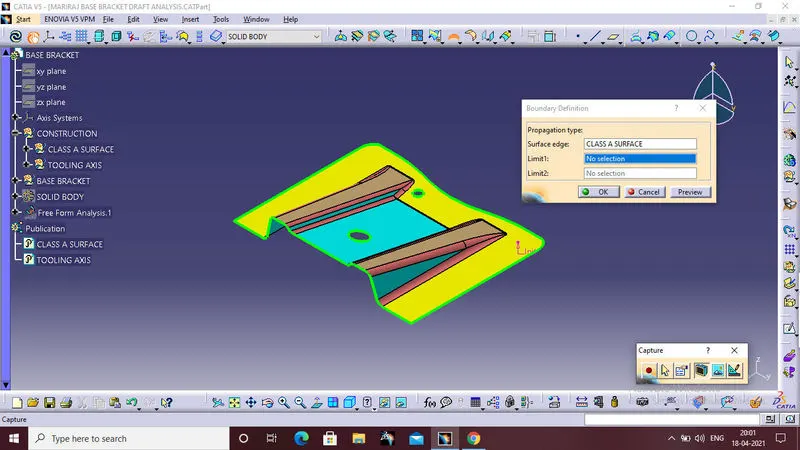
Next step is to check the boundary if there is any gap between the class A surface.
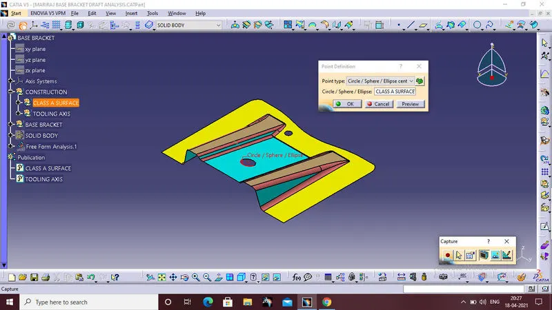
Then create the point at the center of the hole of the class A surface.
A line drawn from the point created and extended in the direction of Z of class A surface.That line is Dummy tooling axis.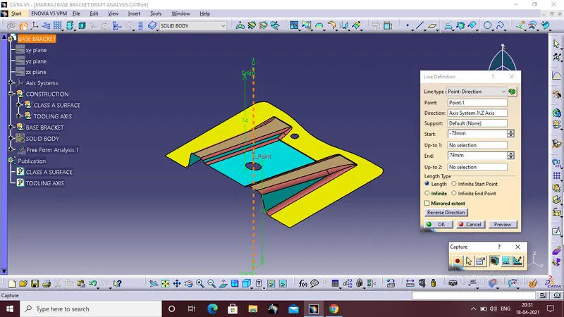
Then insert the axis system at the center point already created at the class a surface.
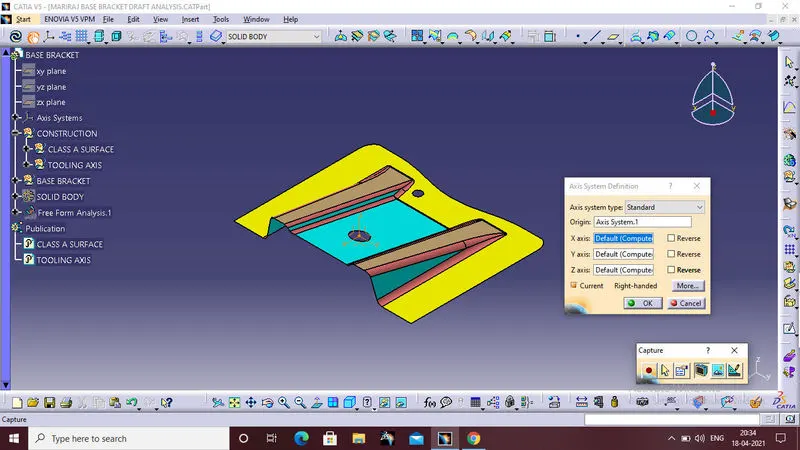
Next step is to create the intersect at yz plane and given class A surface.
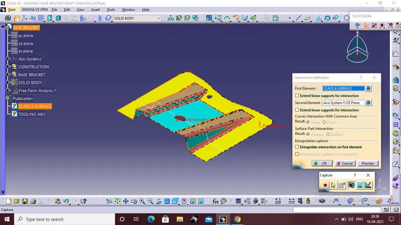
The lines which are perpenticular to the dummy tooling axis are may pass the criteria in the draft analysis,So only the parallel lines from the intersection is taken.
Then insert the point to point line from the line command at the two parellel lines from the intersection.
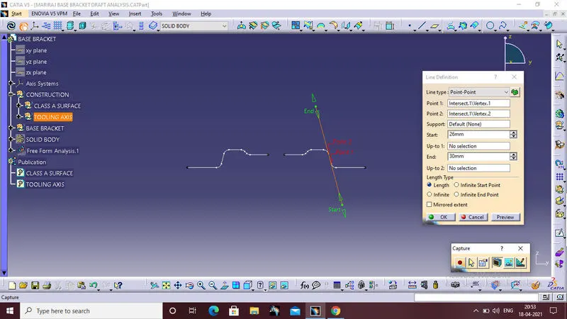
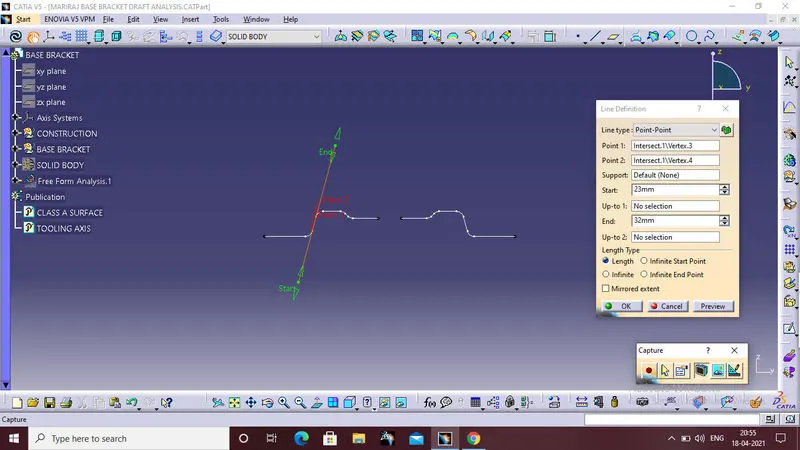
Then created the bisecting line between two parallel line with the reference point of the class A surface.this line is the main tooling axis of the given class A surface.
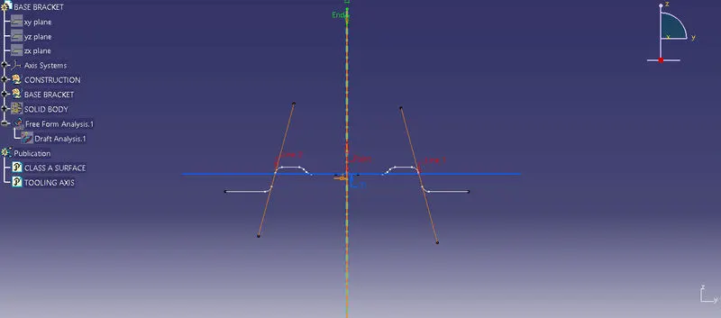
DRAFT ANALYSIS:
Draft analysis is required to check if a part has required draft or not. Draft is required so that a part can be ejected from its mould.This process is called is draft analysis.
PROCEDURE:
- First check for the surface in material mode,if it is not in material mode to change the mode in to material.
- After Tooling Axis Select the Feature Draft Analysis option from the Insert Option .
- Select the element to analyze.
- Next click on Use the compass to define the new current draft direction option and make it align with the tooling axis by dragging it to the axis .
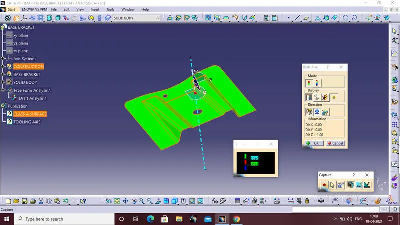
- so after arranging the the compass of the tooling axis if green colour is appeared the draft angle is in bounds according to the given colour code .
- If the angle is under the limit we have to create another axis and tilt the presnt angle opposite to the negative or previous angle so that it will come under the required draft angle.
- so until the optimoised result is obtained we should continue the same operation.
CLASS B SURFACE:
To craete the class B surface,first smplify the given A surface into sperate surfaces like ribs,base surface,slope surface.
First start with the rib surface ,extract the 3 face of the rib1 by using extract command
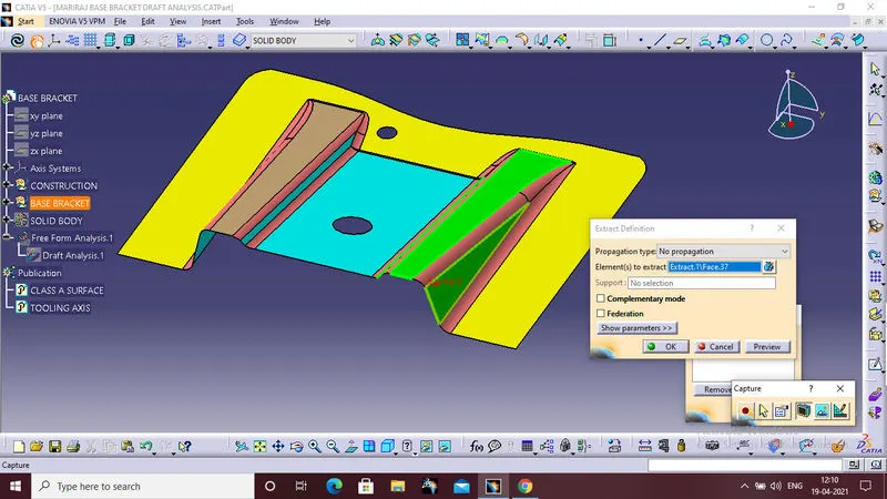
output of the extract is
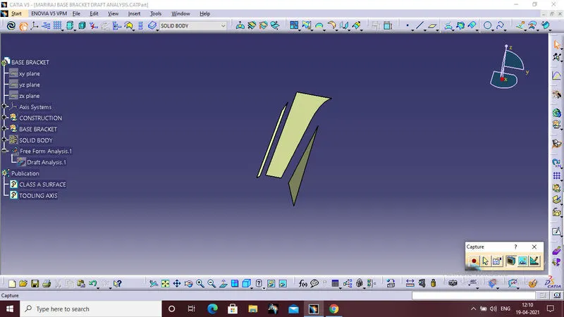
Then untrim the extract surfaces
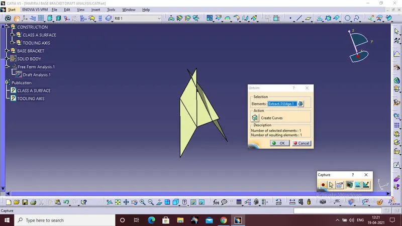
and they are further extrapolated to certain distance that they are intersect each other.
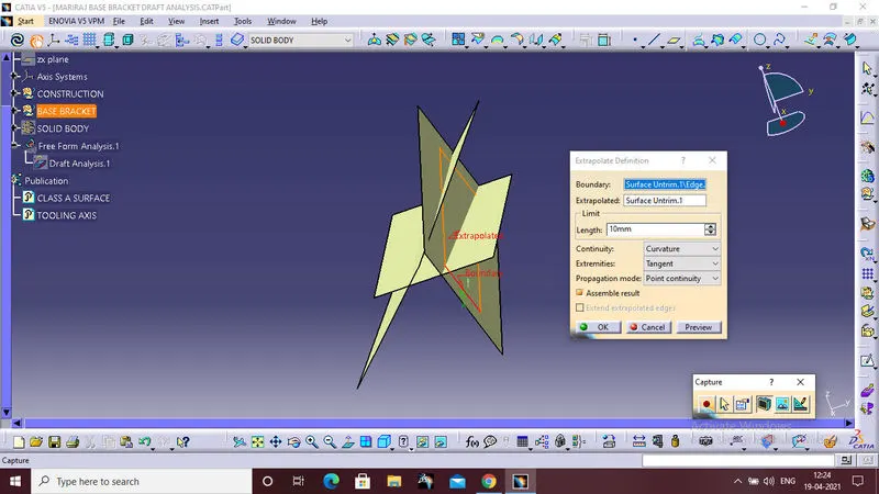
Than trim the first two extrapolated surfaces
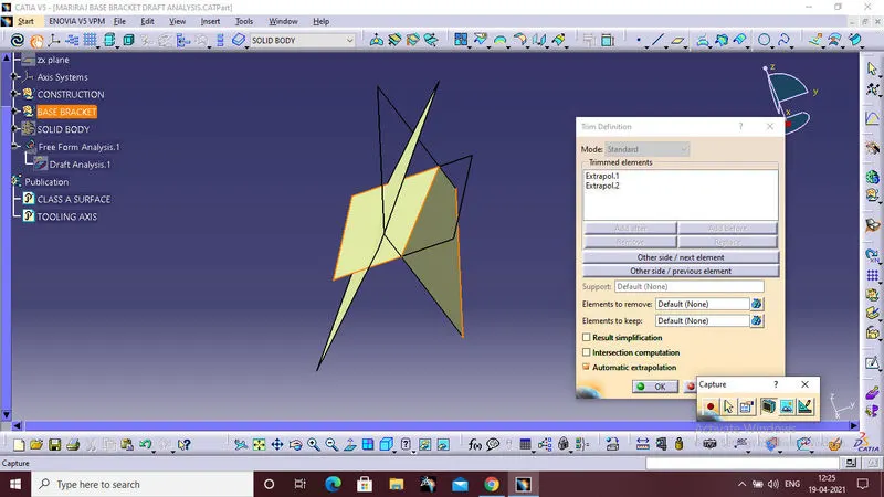
same for other two extrapolated surface
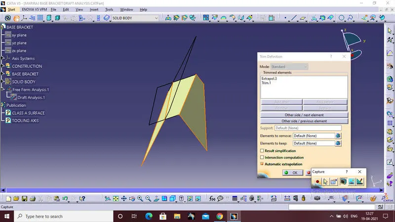
finally we got the rib 1,the thickness of the component is 2.5mm,so offset the surface into 2,5mm by using offset command.
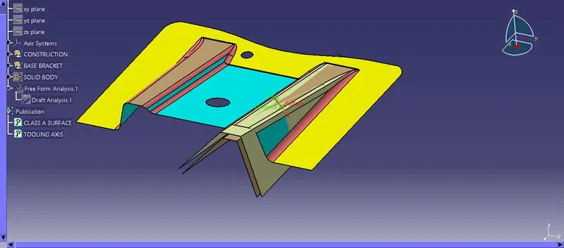
RIB 2:
Using the same procedure for the rib 2 also,
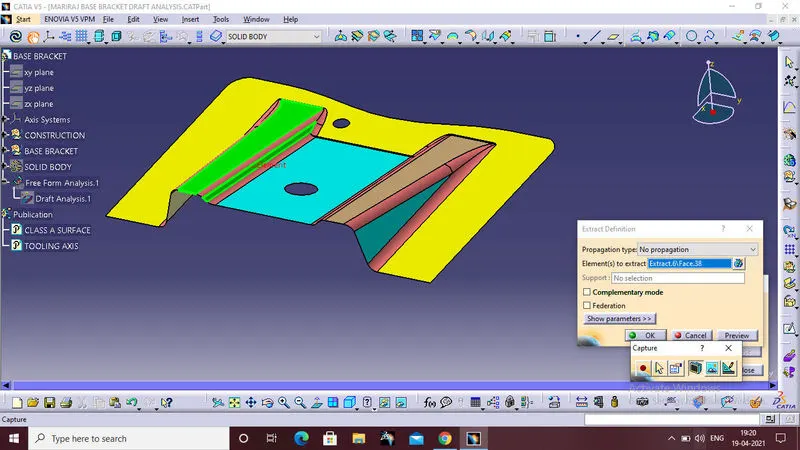
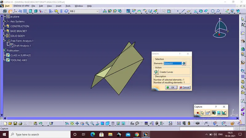
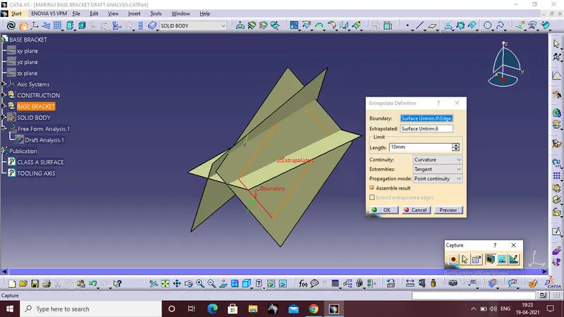
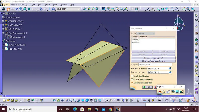
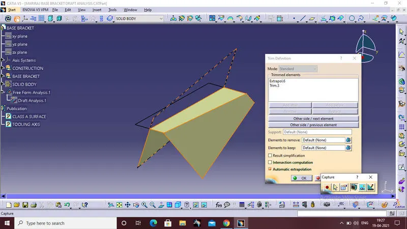
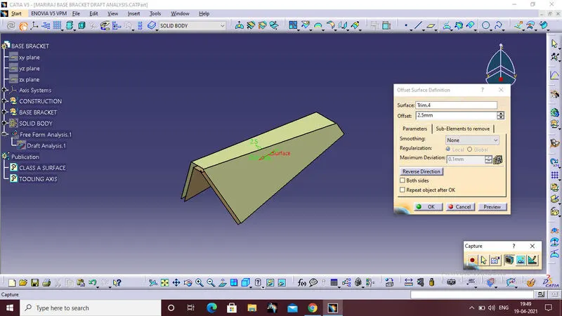
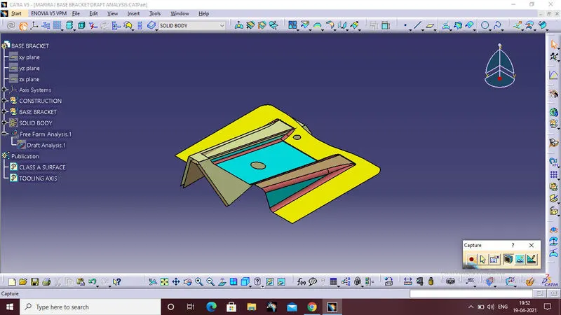
Rib 1 and Rib 2 are completed.
BASE SURFACE:
For base surface first extract the base surface from the class A surface.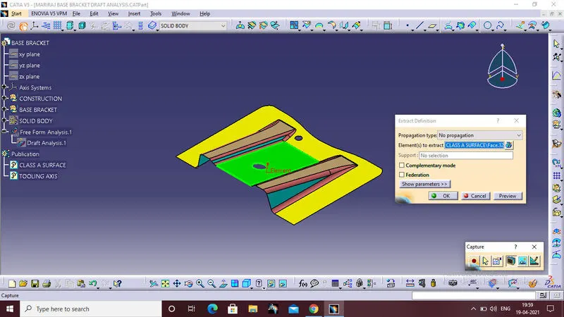
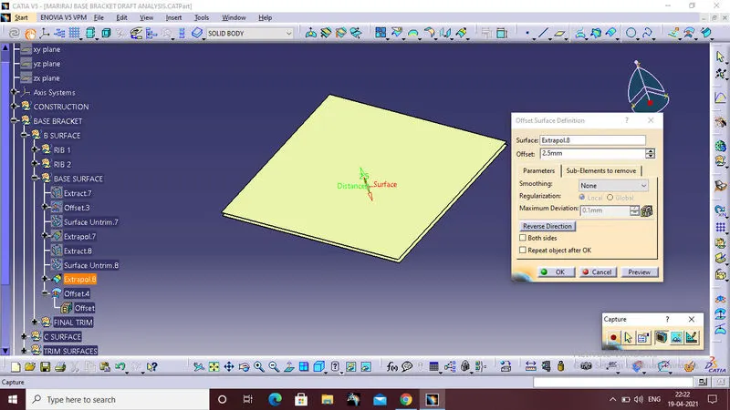
Than offset the extracted surface to 2.5mm,because the thickness of the component is 2.5mm.
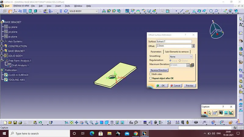
untrim the offset surface to got an perfect shape,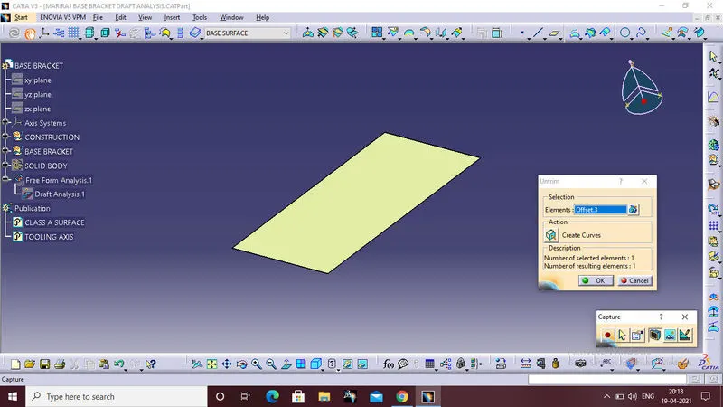
Than extract the outermost surface of the class A surface
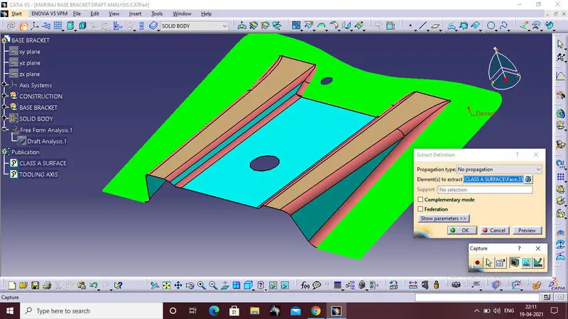
Next step is to untrim the extracted surfaces
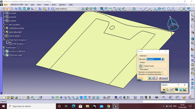
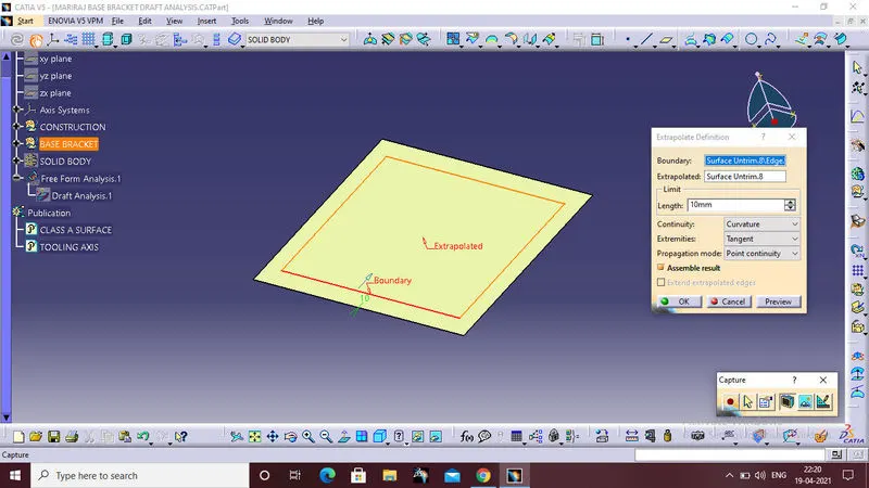
Than extrapolated the untrim surface to get the complete intersect surface.
offset the extrapolated surface to 2.5mm.
Trim the rib surface to inside base surface
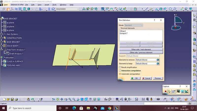
Trim the other side rib surface to base surface
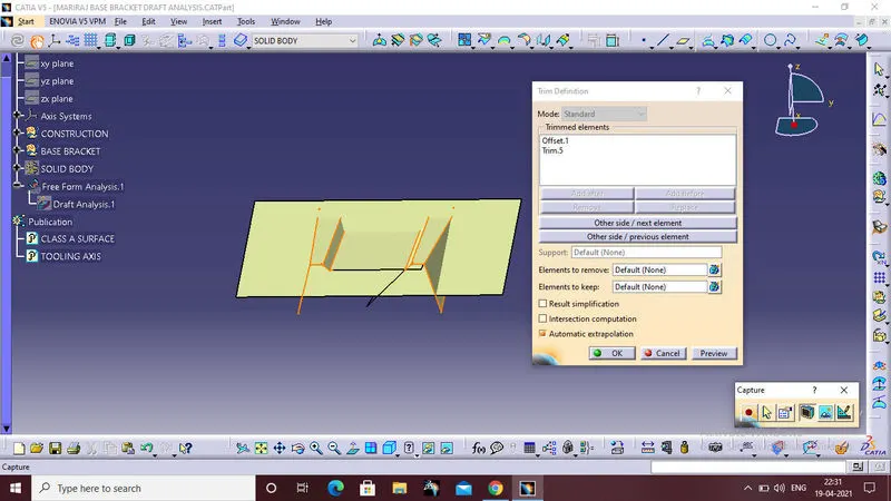
Trim the rib surface into outside base surface
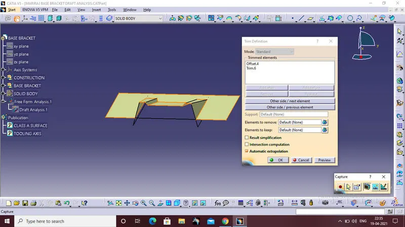
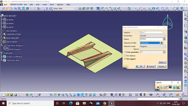
Than give the radius 5.5mm to all edges,because inside radius is 3 and the thickness of the component is 2.5mm,so the outer radius is 5.5mm.
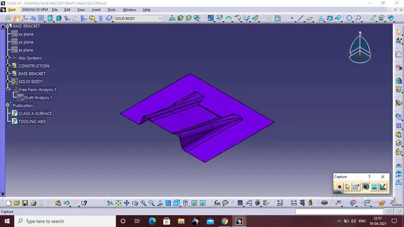
The final trimmed surface is an class B surface
CLASS C SURFACE:
Class C surface is an connecting surface of an class A surface and class B surface.
Procedure for making class C surface:
First step is to extract the outer boundary of an class A surface and extract the hole surfaces.
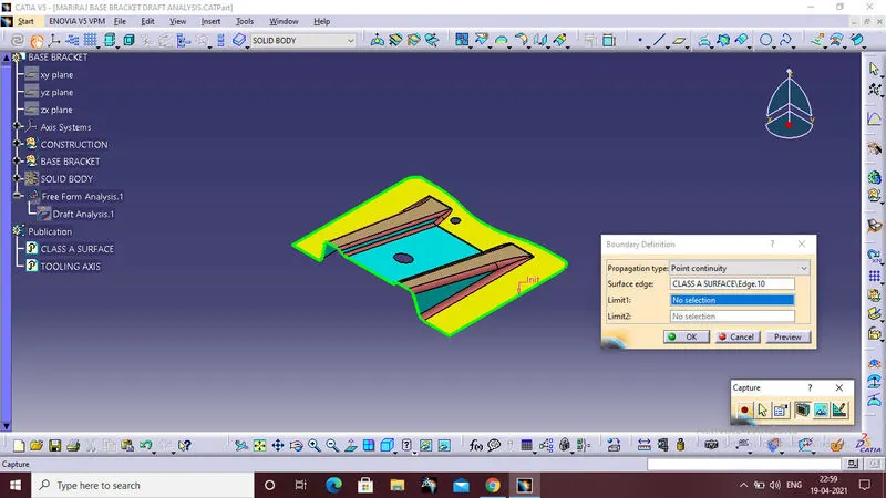
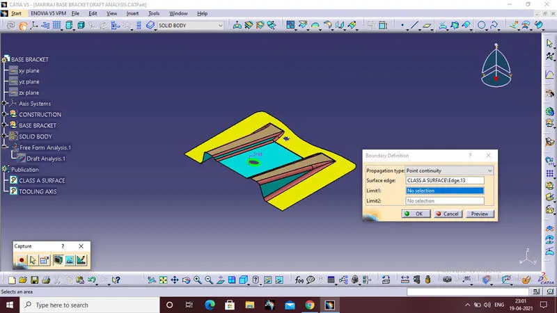
Next step is to swpet the last extract boundary by using swept command.
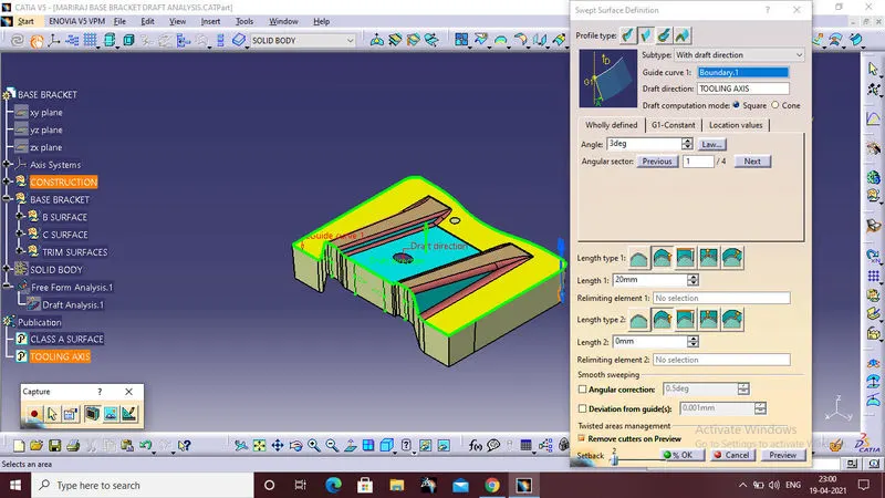
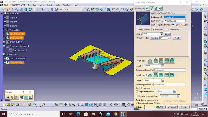 Than join the class A surface and sweep1 ,sweep2 to make complete joined surface.
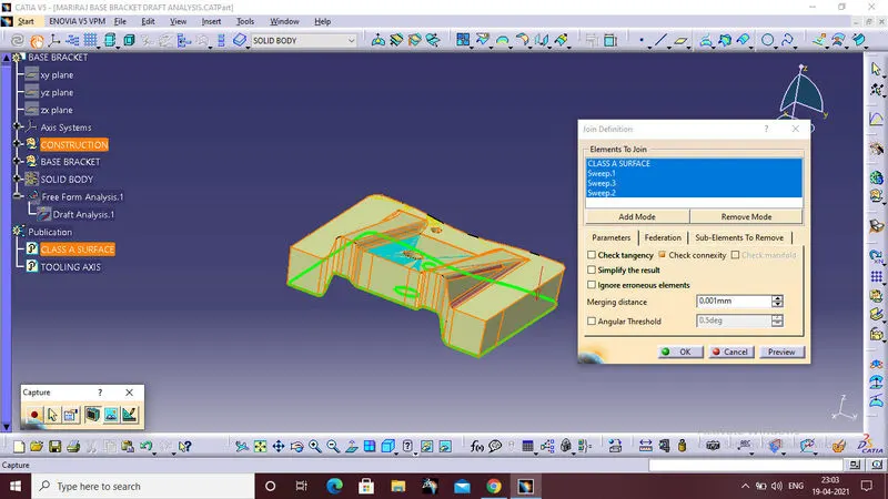
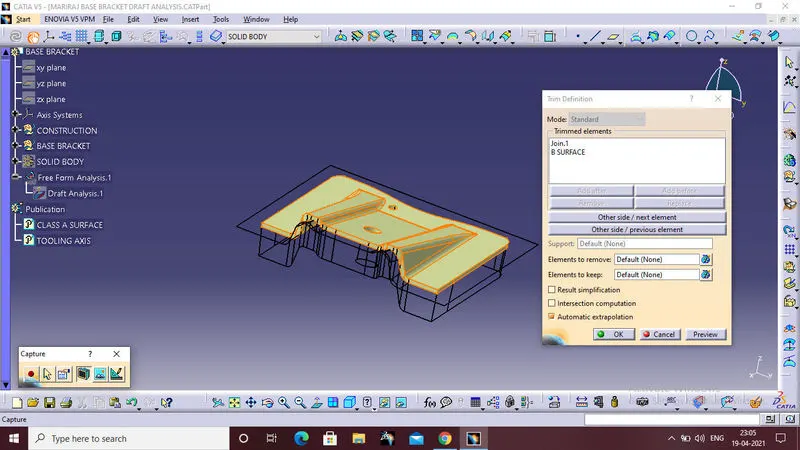
finally Trim the join 1 and class B surface to get the completely closed surface.This surface is an combination of class A ,classB and class C surface.
SOLID BODY:
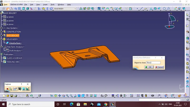
Final part is needed to in the form of solid body,so the surface part is to be converted in to an solid body.
PROCEDURE:
First select the part design workbench in catia,Than select the closed surface commnd in toolbar,and select the final close surface from the surface workbench.The final result will be the closed solid body.
The wall thickness of the final closed body is 2.5mm.
VIEWS:
Front view:
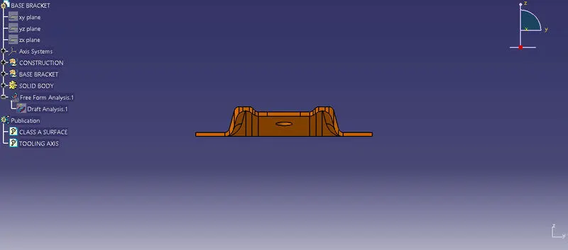
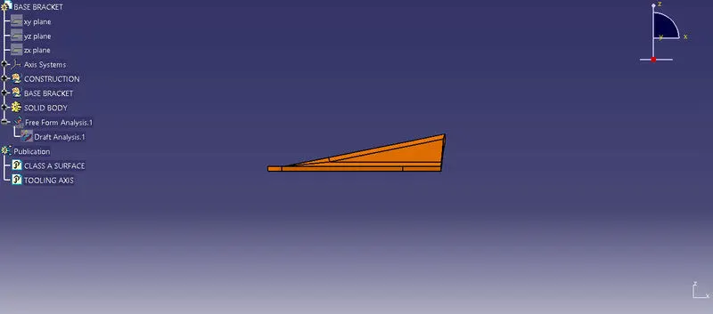
Side view:
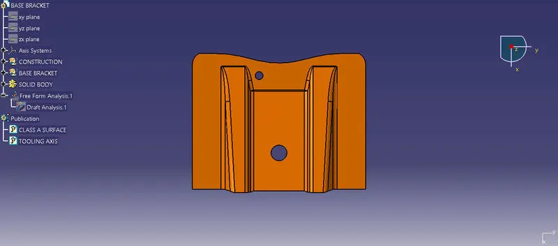
Top view:
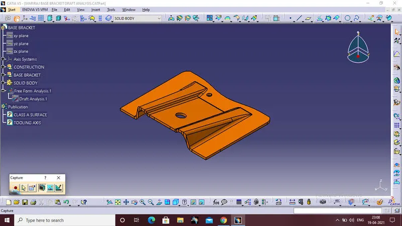
Isometric view:
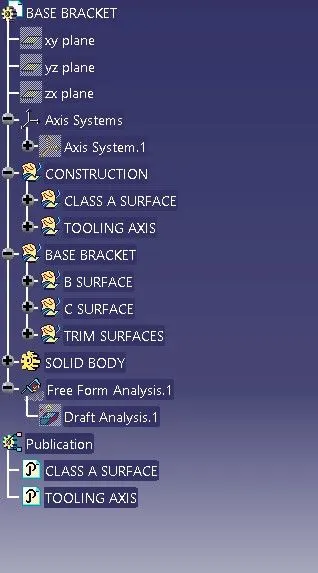
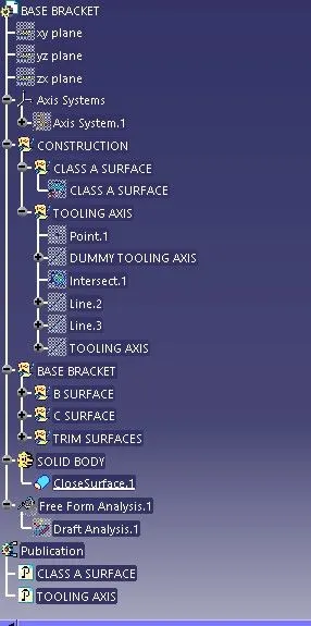
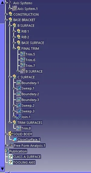
Tree structure:
PUBLICATION:
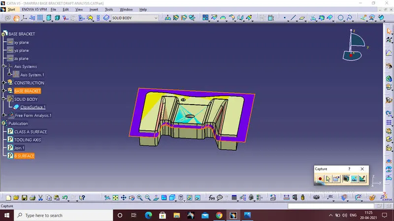
To publish the class A surface and the Tolling axis outside from the geometrical set.
Publications allow you to modify a model without invalidating the features defined in the analysis document. If you modify the entity to which a publication refers in a CATIA V5 part or assembly, all of the features in the analysis document using that publication are updated to refer to the new entity.
RESULT:
The creation of the Base Bracket Plastic component through the given Class-A surface,and the tooling axis for the given Class-A Surface should be created meeting the requirements and the draft angle and at the end perform the Draft analysis on the model are sucessfully completed by using catia software.