Designing a Wheel Cover in CATIA V5: A Hands-On Guide
Learn how to design a wheel cover in CATIA V5 with this step-by-step hands-on guide. Perfect for beginners and professionals alike, master essential tools and techniques to elevate your design skills.
 Alda Rovina·9 Sept 2024·5 min read
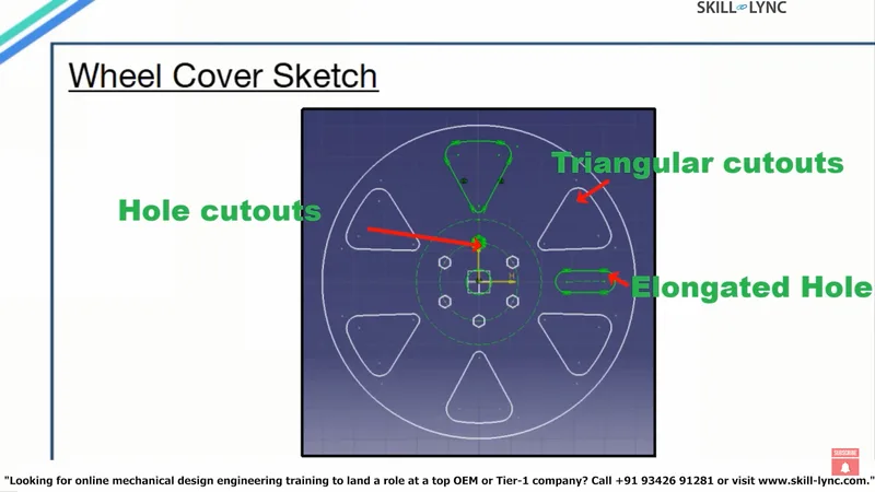
Welcome back to our CATIA design series! Today, we're diving into an exciting project—designing a wheel cover using CATIA V5. If you’re eager to sharpen your skills or tackle a new challenge, this hands-on guide will walk you through the entire process, step-by-step. Whether you’re a beginner or a seasoned professional, by the end of this guide, you’ll have mastered key tools and techniques that can be applied to various design projects in CATIA.
Let’s jump right in!
Step 1: Setting up your project
Before we begin sketching, let’s get our workspace in order.
1. Open CATIA V5 and navigate to the Start menu, select Mechanical Design, and then head to the Sketcher Workbench.
2. Give your part a name—let’s call it “Wheel Cover.”
3. Be sure to keep the Create a Geometrical Set option checked. This will help you organize your design. Save the file in a location you can easily find later.
Quick Tip: Want to rename your part later? No problem! Just right-click on the part name in the Specification Tree, go to Properties, and update the name. You can also add a description or version information while you're there.
Step 2: Creating the basic sketch
With our setup done, it’s time to roll up our sleeves and start sketching. We'll begin by creating a reference point:
1. Select the Point option from the Reference Elements toolbar.
2. Leave the XYZ components set to zero and click OK.
Next, we’ll create a base sketch on the YZ plane.
1. Click on the Sketch Toolbar and select Position Sketch.
2. Choose the YZ plane as the reference and select Point 1 from the Specification Tree.
Make sure everything is aligned as shown on your screen. Feeling a bit off? No worries, use the Reverse V, Reverse H, and Swap checkboxes to make adjustments as needed. Once you’re ready, click OK to start sketching.
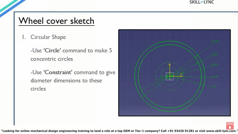
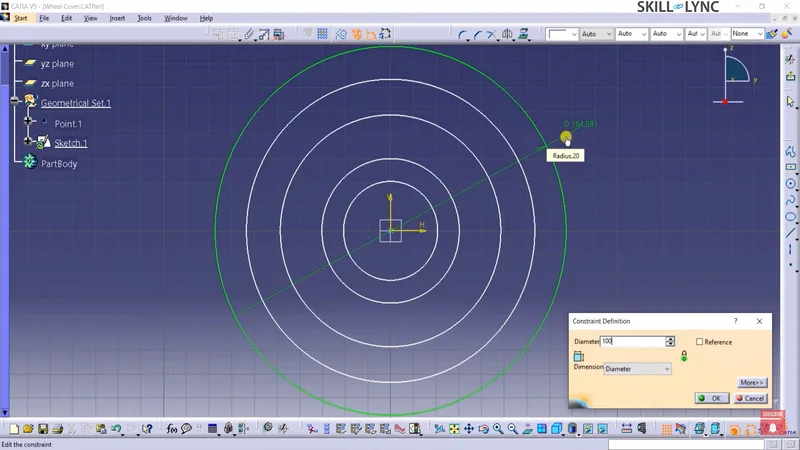
Your Task: Draw five concentric circles using the Circle command from the Profile Toolbar. These circles will form the foundation of the wheel cover.
Step 3: Adding triangular cutouts
Now comes the fun part—creating those sleek triangular cutouts!
1. Use the D90 and D40 circles as references. Start by drawing a vertical line using the Axis Option in the Profile Toolbar.
2. Draw another line from the intersection of the D40 circle and the vertical axis, extending it to the D90 circle.
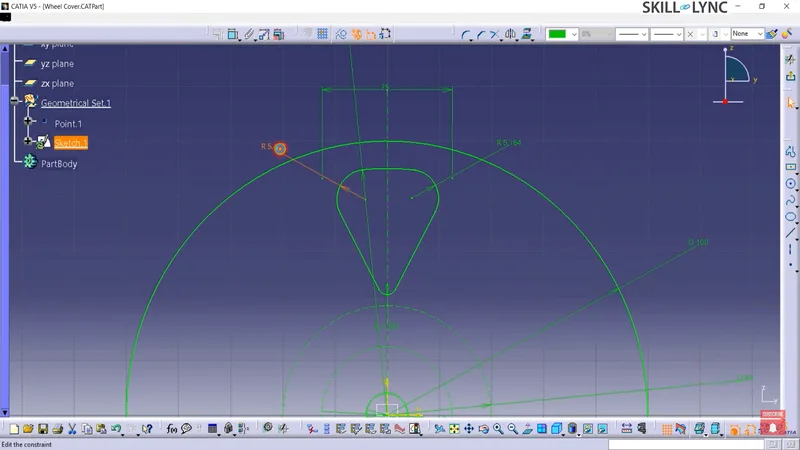
You’ll notice the line isn’t fully constrained yet—it’s moving! To fix this, let’s add an angular dimension. Before we proceed, use the Mirror Command to reflect the line across the vertical axis.
Now, constrain the distance between the two lines to 25mm.
Pro Tip: To add smooth curves to the cutout, use the Corner Command and round the edges. Set the corner radius to 4mm for the upper corners and 2mm for the bottom.
Step 4: Creating a circular pattern
Ready to make your design pop? Let’s create a circular pattern using the Rotate Command.
1. Select all the edges of your triangular cutout.
2. Go to the Operation Toolbar and click Rotate.
3. Set the number of instances to 5, and with Duplicate Mode checked, rotate the cutouts by 60 degrees.
Now, you should see five triangular cutouts evenly spaced around the wheel cover.
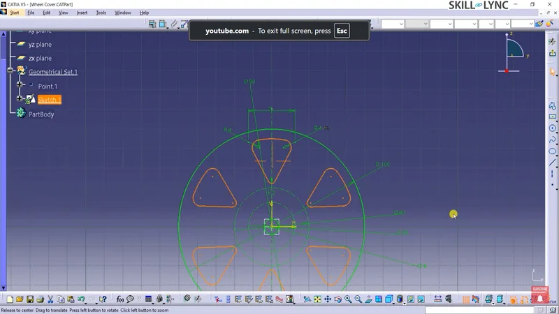
Quick Challenge: Can you tweak the rotation angle or the number of instances for a custom design? Experiment and see what creative variations you can come up with!
Step 5: Adding hole cutouts
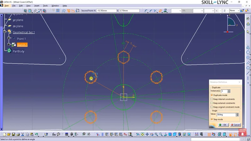
Next, we’ll add some hole cutouts to the inner construction circle.
1. Select the Polygon Command from the Profile Toolbar and place a hexagon on the D25 circle.
2. Constrain one side of the hexagon to 2mm.
Now, just like with the triangular cutouts, use the Rotate Command to create five more instances of the hexagon around the D25 circle.
Step 6: Creating an elongated slot
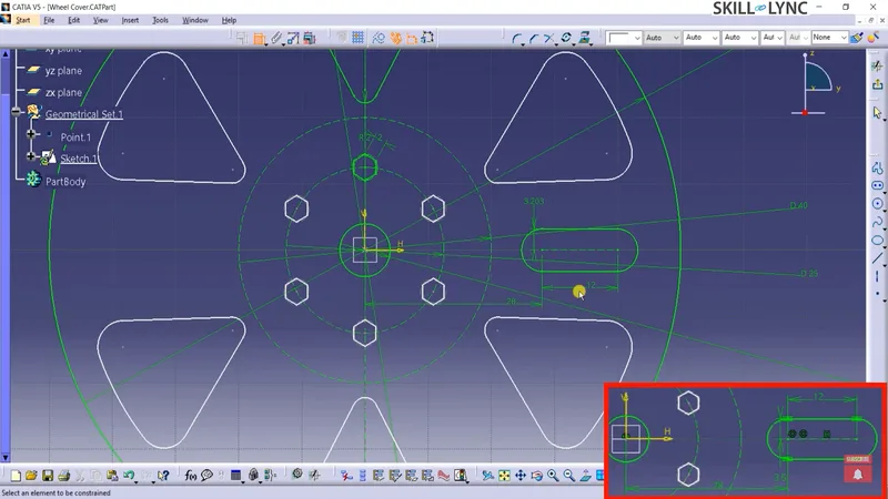
We’re almost there! To finish off the sketch, we’ll add an elongated slot:
1. Select the Elongated Hole Command from the Profile Toolbar.
2. Define the start point, end point, and radius of the slot’s curved edge.
Once the slot is in place, use the Constraint Command to dimension and fully define its position. For example:
- Distance from the central vertical axis: 28mm
- Distance between start and end points: 12mm
- Slot radius: 3.5mm
Wrapping up the sketch
And just like that, your wheel cover sketch is complete! You can now exit the workbench by clicking on the Exit Workbench icon. If you need to make any edits, just double-click on Sketch 1 in the Specification Tree.
Pro Insight: Want to check the quality of your sketch? Use the Sketch Solving Analysis tool to check for under-constrained elements. While rotated instances may not be fully constrained, the geometry should be accurate and ready for creating a solid model.
You’ve just completed the sketch for a wheel cover in CATIA V5! Stay tuned for the next part of our series, where we’ll take this 2D sketch and turn it into a 3D model.
Challenge: Try applying these techniques to other designs! What about designing a fan blade or a custom gear? The possibilities are endless when you master the tools in CATIA V5.
This blog is part of our ongoing CATIA Design Series. If you missed the previous posts, check them out here
Would you like to have a more interactive experience going through the CATIA user interface?
Skill-Lync has released a FREE comprehensive course covering CATIA in detail! check it out here
Right from the user interface's fundamentals, menus and options, this course covers most aspects of the tool from a practical perspective. It even includes a certificate to add to your resume after completion!
Check out our hands-on course today and add CATIA to your list of skills!
Let’s get #IndustryReady together, one skill at a time!


