Week 8 - Challenge 2 - Base Bracket Design
OBJECTIVE:
To create the tooling axis for the base bracket model and perform the Draft Analysis.
Draft Analysis Feature:
This command is used to detect if the part you drafted will be easily removed. This type of analysis is performed based on colour ranges identifying zones on the analysed element where the deviation from the draft direction at any point, corresponds to specified values.
Draft is the angle in which the part is tapered to allow it to release. As the part cold, it tends to want to shrink to the core side of the mould. Adding draft helps the part to release the part.
Tooling Axis: The direction in which the mould or core cavity opens.
Tooling Axis Creation:
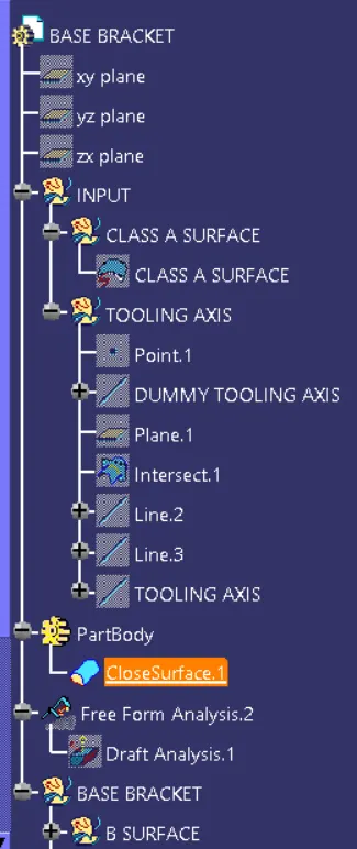
The connectivity of the CLASS A Surface can be determined by creating boundaries or by using joint command and see how well it is connected. This is the first step to check the continuity of the CLASS A Surface.
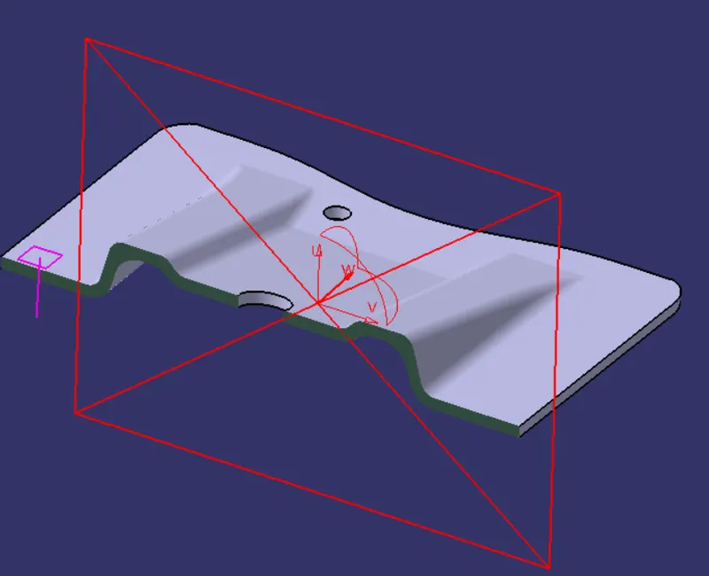
The clearance checking along all the axis direction will be done by creating an intersection along an axis on a plane by creating a new axis system with the model and constructing two lines contact with the walls, the line bisecting the two lines and passing through the point will be tooling axis.
A Dummy tooling axis is directly created by point to direction line command.
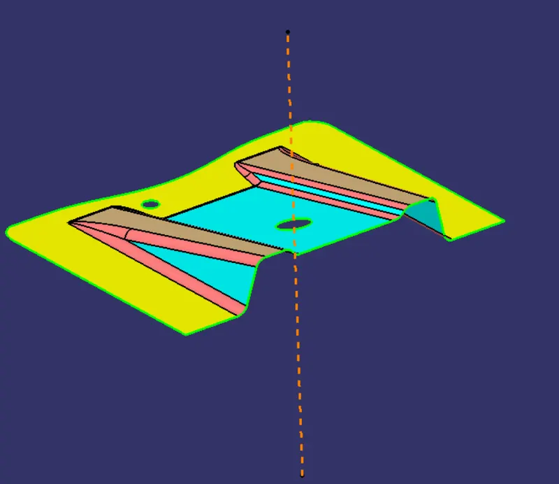
Creating The Tooling Axis using Bisecting Method:
Using the intersection command the lines created along the inclined walls, these lines are used for creating the tooling axis.
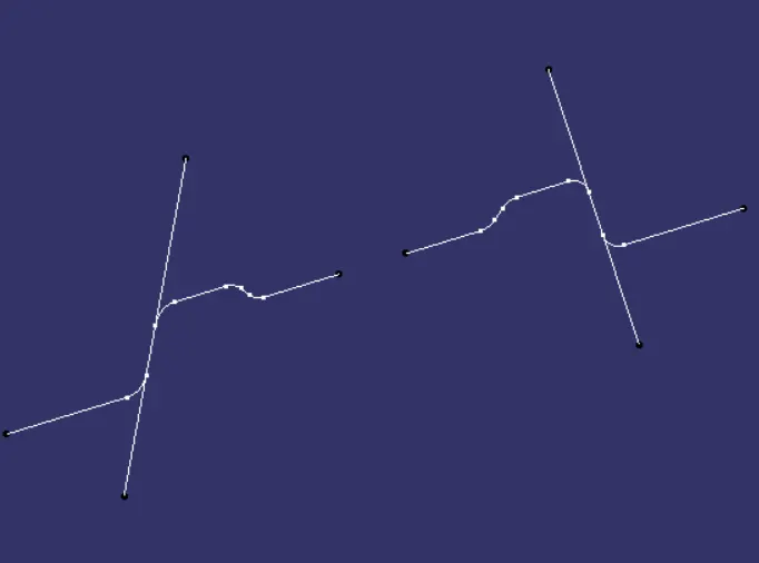
In the line command the Bisecting option is selected and then both inclined lines selected along with the point created at the center of the part.
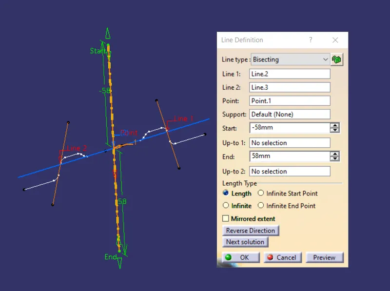
Then the bisecting line is created. Rename this line as Tooling Axis.The Tooling Axis is created and to visualize more easily add colour to it convert into dash line.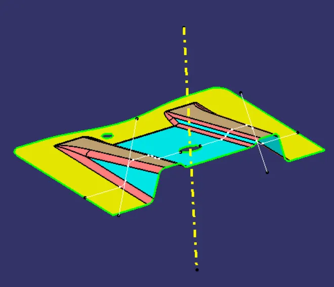
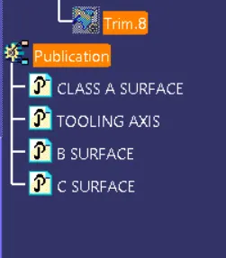
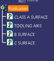
PUBLICATION:
Publication is used to make easily accessible of the published components.
Publish the
1. Tooling Axis
2. Class A surface
3. Class B Surface
4. Class C surface
DRAFT ANALYSIS:
Draft Analysis is done after determining the tooling axis.
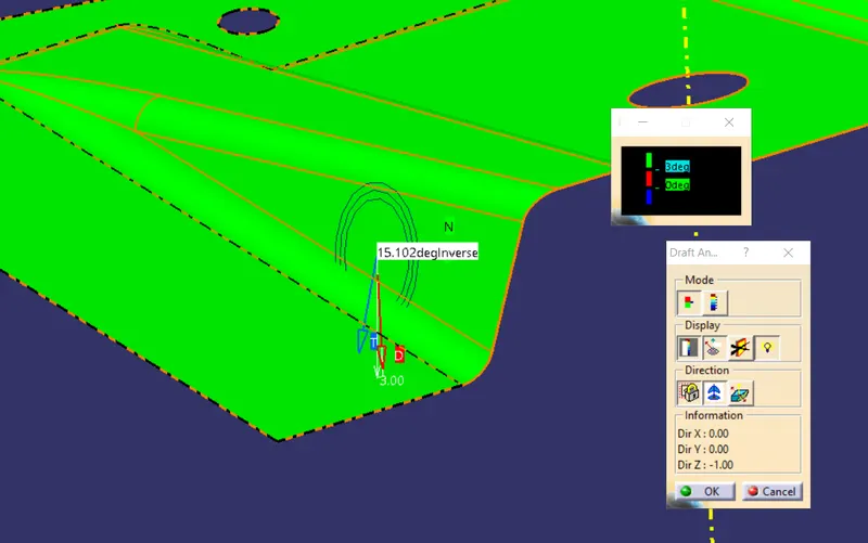
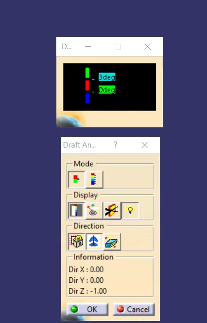
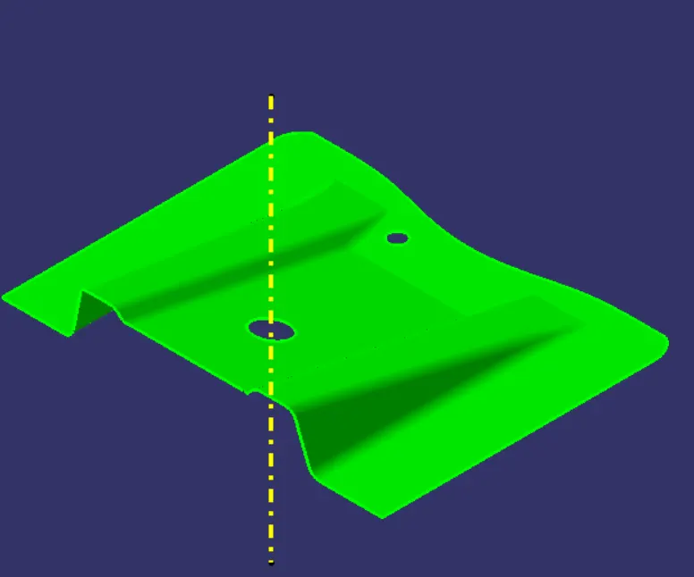
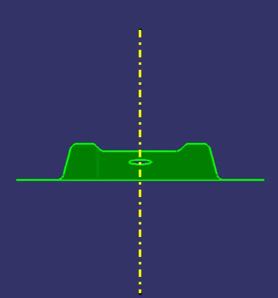
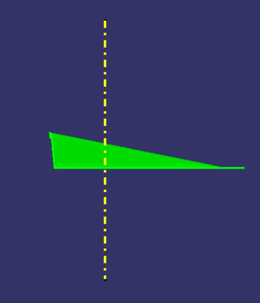
Draft Analysis is used to check whether the minimum 3 degree draft is maintained. If the minimum 3 degree is provided then the whole part is turned into green.
1. Make sure the view selected to materials.
2. Select the Feature Draft Analysis Icon.
3. Drag the compass from its postion to the Tooling Axis.
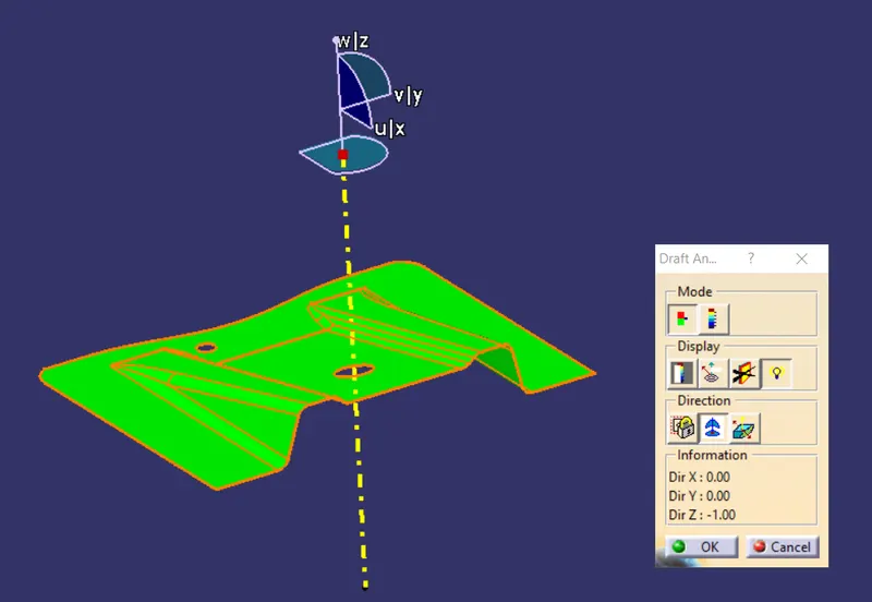
4. Select at the lock compass.
5. Touch on the model if it gets green means draft is under 3 degree limit.
6. Select the Analysis under Running Point where draft is to be measured.
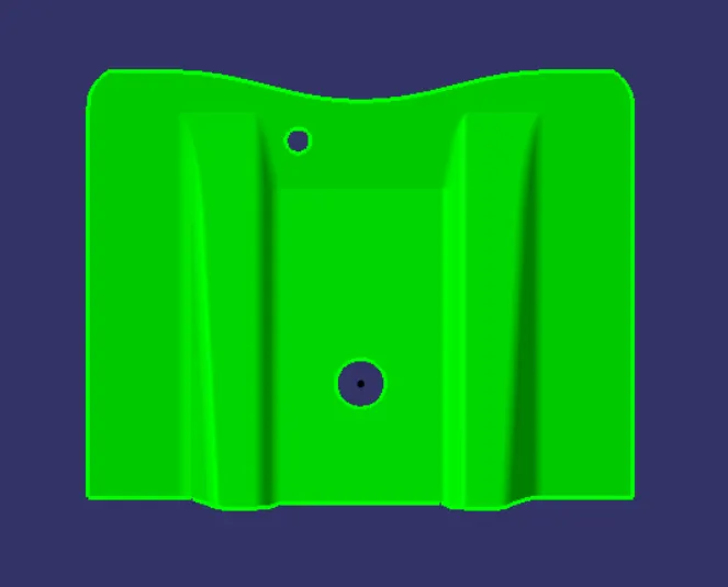
CREATION OF CLOSED BODY:
Creation of Class-B Surface:
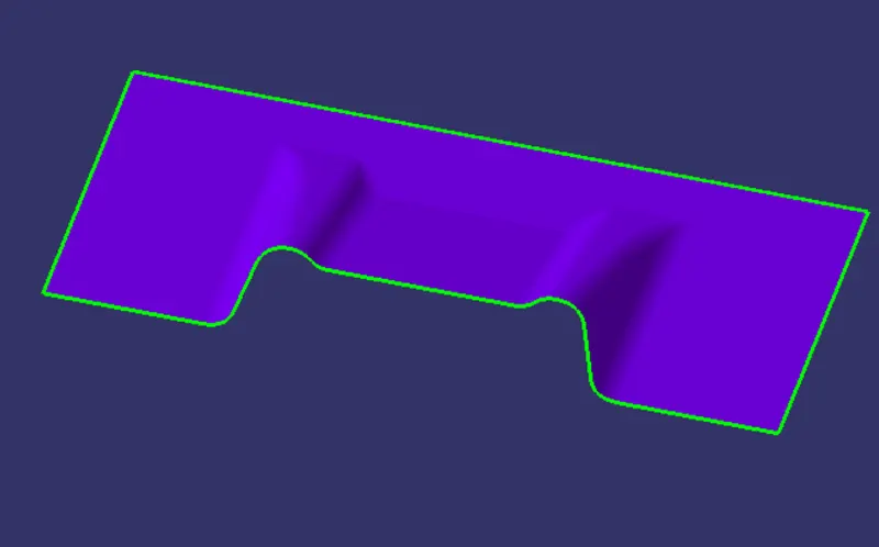
Class-B surface is the back side surface with respect to the Class-A Surface which is aesthetic surface, Class B surface carries the engineering features like Ribs,Bushes etc. which are on the back side and not visible to the eye.
This surface is used to determine the Thickness of the component. We can make B-surface in may ways.
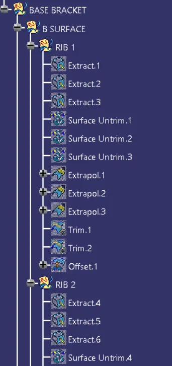
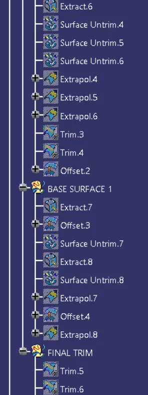
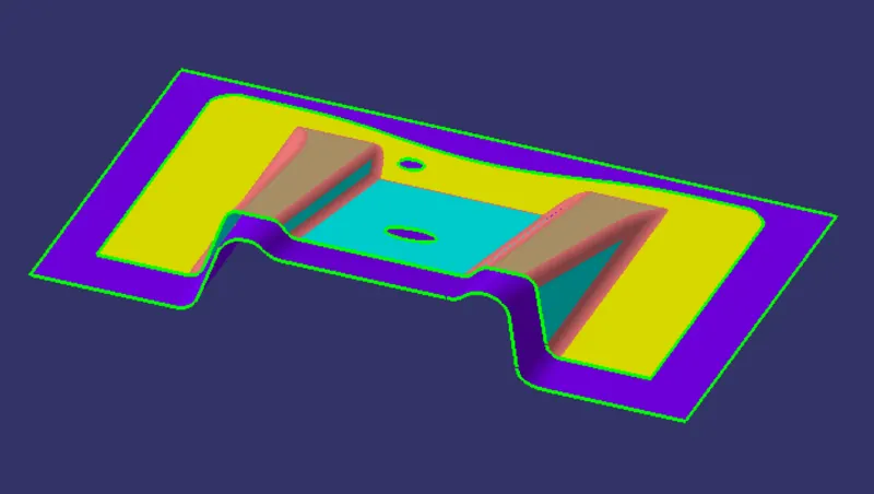
Extracting the straight surfaces and then by using untrim option we have extended surfaces.After theat we use extrapolate command to extend the surfaces even further.After that We trim the Surfaces to the desire shape and make the the offset the shape below the class a surface by 2.5mm.
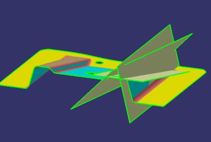
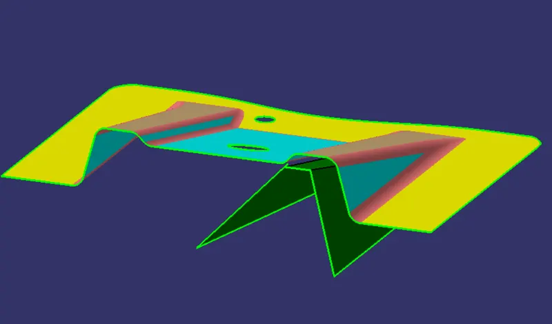
We repeat the same process for another rib. After that extract the base surface and upper surfacew of the Class A Surface and offset it by 2.5mm and then extrapolate the surfaces afetr that use the trim option to trim excess surfaces and get the desired shape.
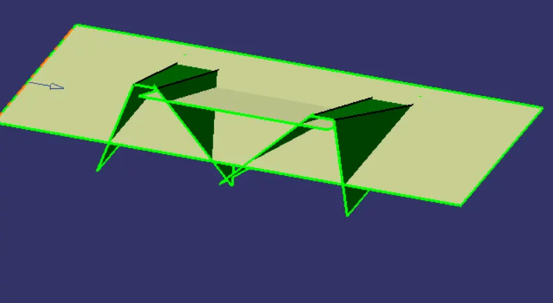
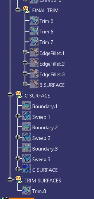
After trimming the surafce make fillet to the surface.
Creation of Class-C Surface:
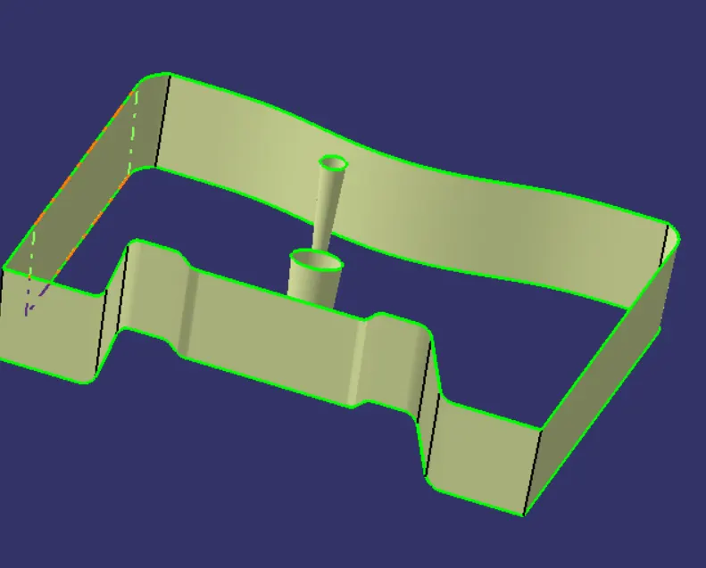
Class C Surface is basically a bridge or connector which connects the Class A Surface to The Class B Surface.
We can make the Class C surface with the help of sweep command. For Profile we use the boundry command to extract the profile of the class A Surface And for the diretion we use the Tooling Axis.
For best result we sweep the holes in the class c surface to ensure perfectly closed surface.
After Class C Surface we need to trim the class B Surface to class C Surface to make the closed surface.
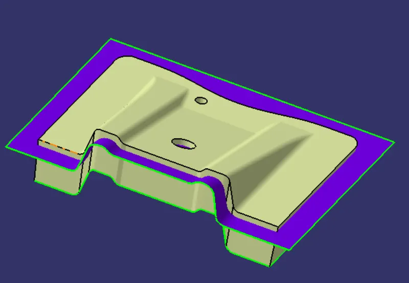
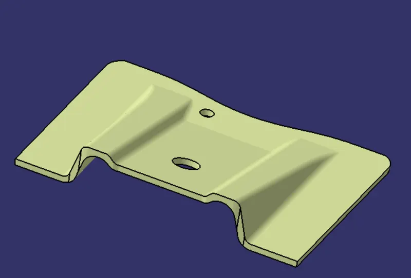
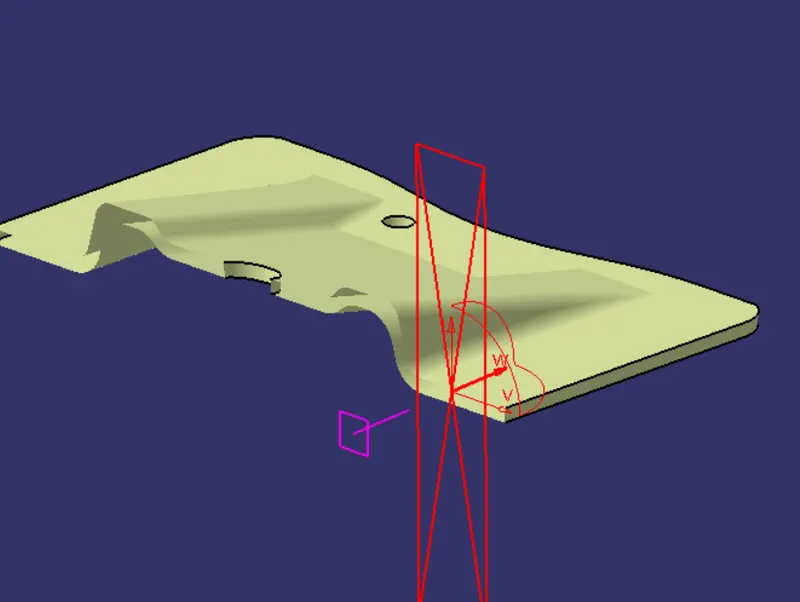
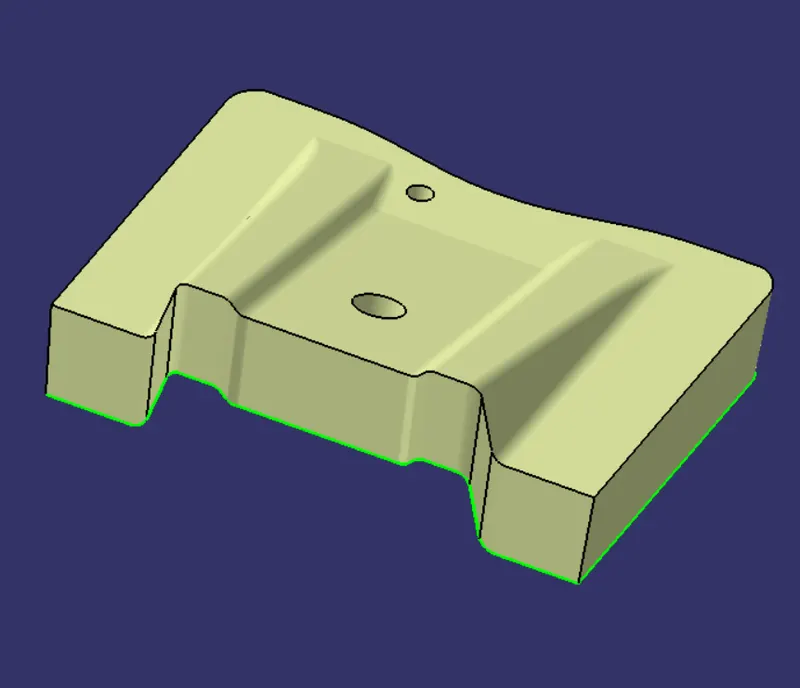
After we have the closed surface we go to the Part Design and choose the Closed Surface feature to make the surface into hte solid body.
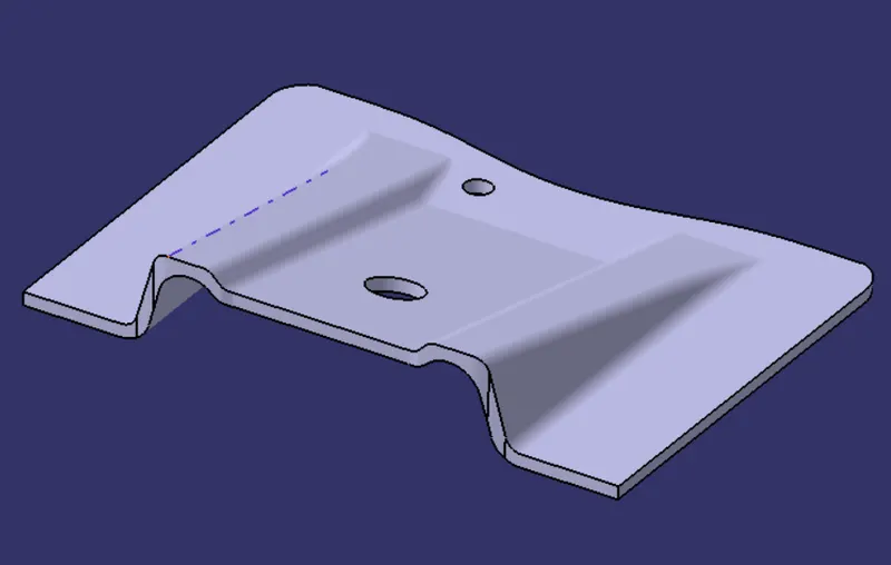
The Final output is the Solid Body.