Week 11 - Final project
OBJECTIVE:
- To create thickened part of door panels using master section for reference.
- To create Class B and Class C Surface and Tooling Axis.
- To create Solid Body from the Surface using Close Surface Feature.
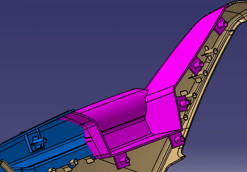
- To create mounting features such as Dog House, Push Pin etc.
- To perform Draft Analysis on the model.
PROCEDURE:
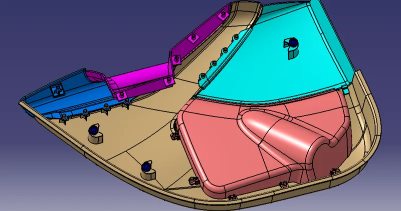
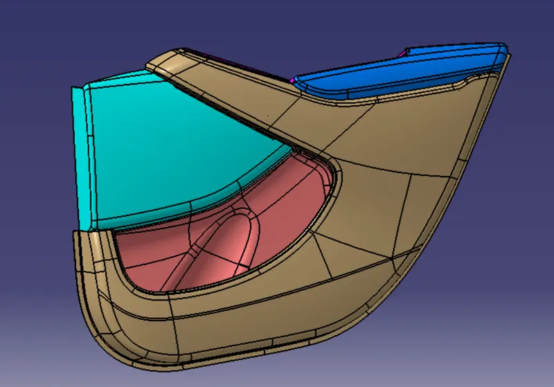
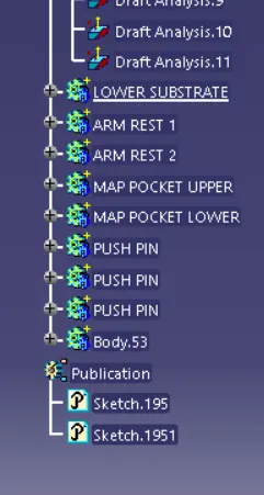
There are 5 components to create for the Door Panel:
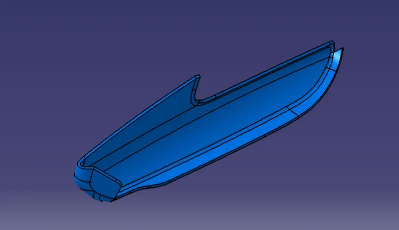
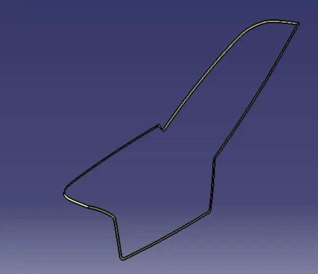
- Lower Substrate
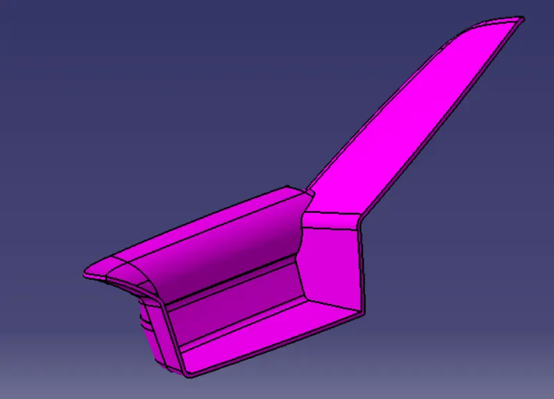
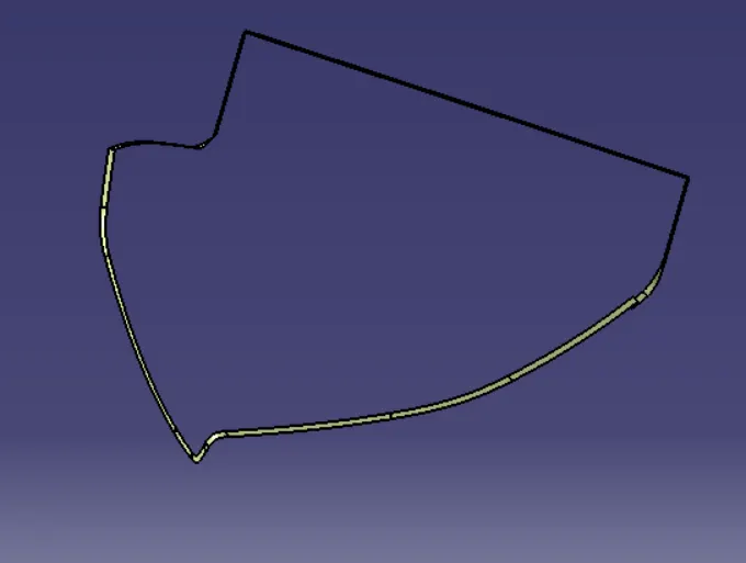
- Arm Rest 1
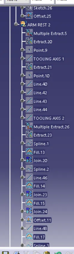
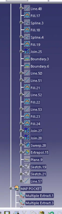
- Arm Rest 2
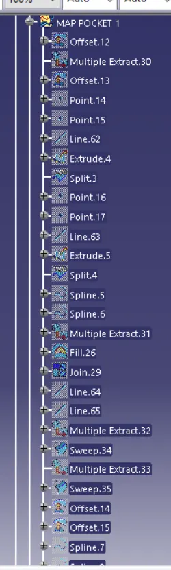
- Map Pocket Upper
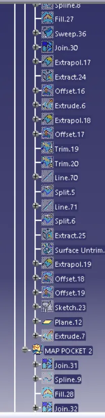
- Map Poket Lower
TOOLING AXIS CREATION:
The connectivity of the CLASS A Surface can be determined by creating boundaries or by using joint command and see how well it is connected. This is the first step to check the continuity of the CLASS A Surface.
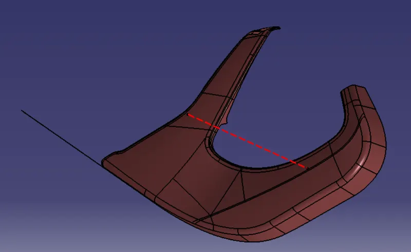
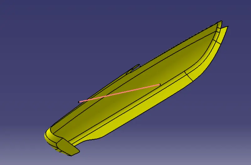
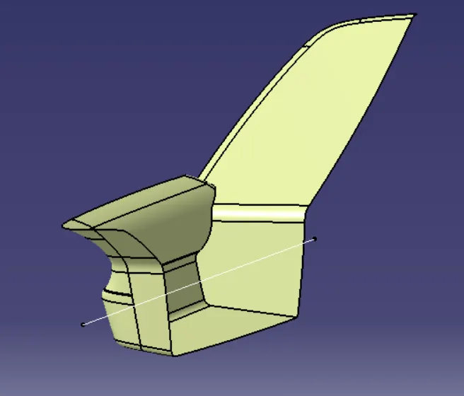
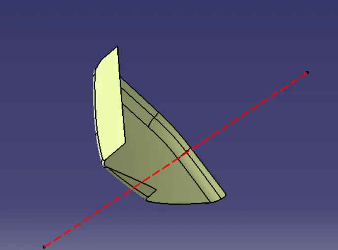
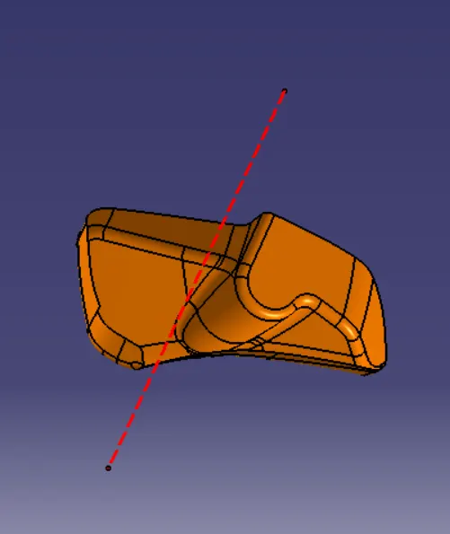
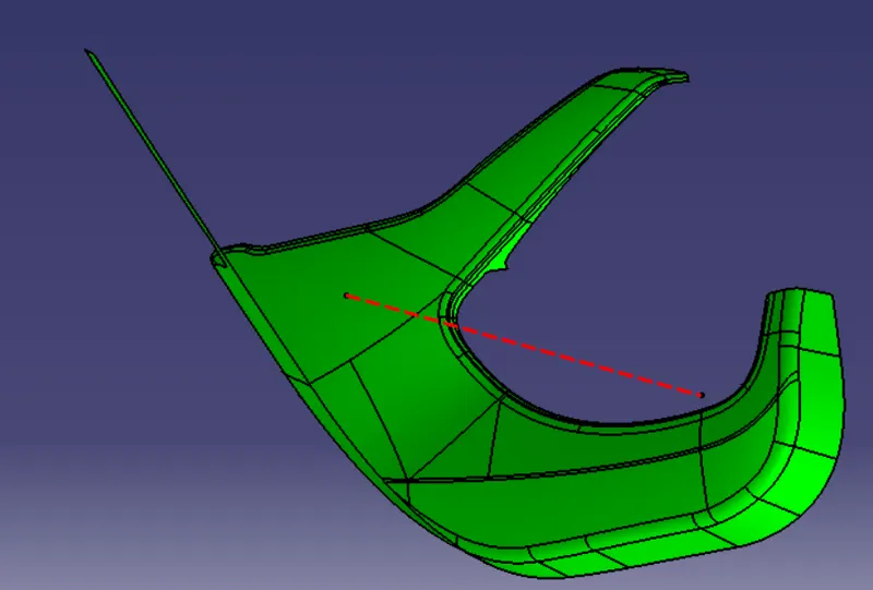
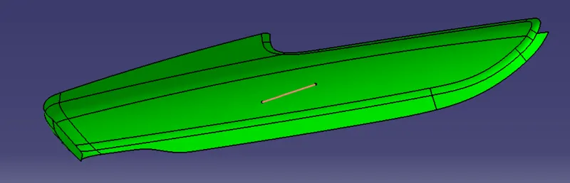
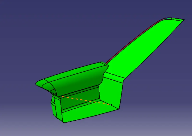
The clearance checking along all the axis direction will be done by creating an intersection along an axis on a plane by creating a new axis system with the model and constructing two lines contact with the walls, the line bisecting the two lines and passing through the point will be tooling axis.
Tooling Axis Creation Using Bisecting Method:
Using the intersection command the lines created along the inclined walls, these lines are used for creating the tooling axis along the Y-Axis.
For Tooling Axis the line command is selected in which bisecting option is selected after that Both Tooling axis X-Axis and Y-Axis are selected along with The point which is created at the center of the part.
The Tooling Axis is created and to visualize more easily add colour to it convert into dash line.
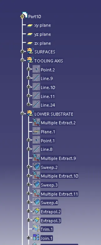
1. Lower Substrate:
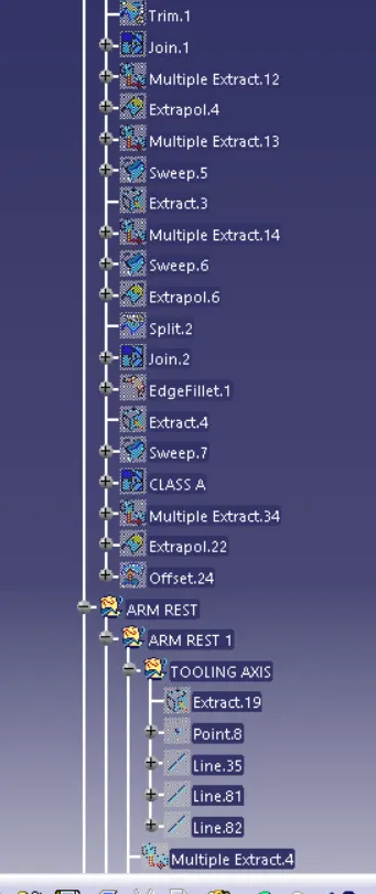
2. Arm Rest 1:
3. Arm Rest 2:
4. Map Pocket Upper:
5. Map Pocket Lower:
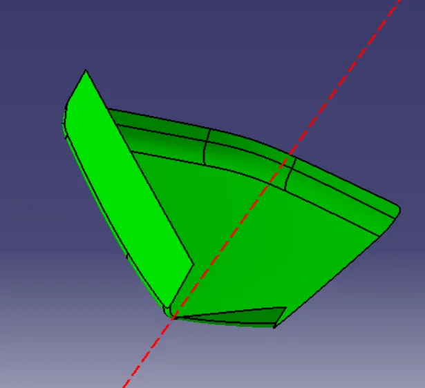
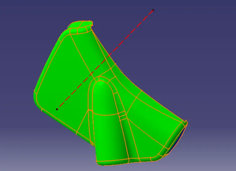
Draft Analysis on Class A Surface:
Draft Analysis Feature:
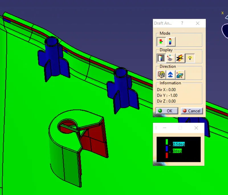
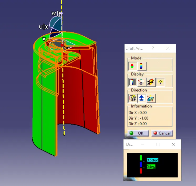
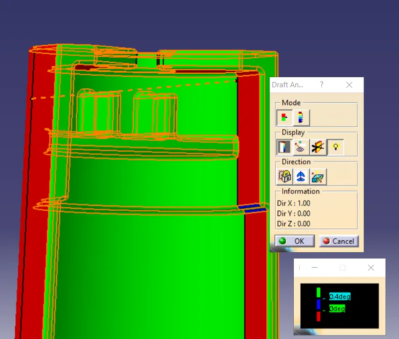
This command is used to detect if the part you drafted will be easily removed. This type of analysis is performed based on colour ranges identifying zones on the analysed element where the deviation from the draft direction at any point, corresponds to specified values.
Draft is the angle in which the part is tapered to allow it to release. As the part cold, it tends to want to shrink to the core side of the mould. Adding draft helps the part to release the part.
Creation of Class B Surface:
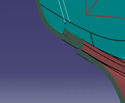
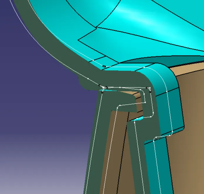
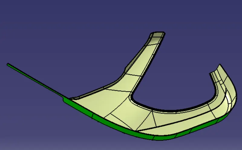
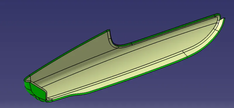
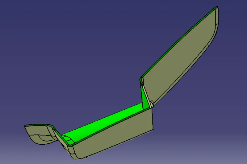
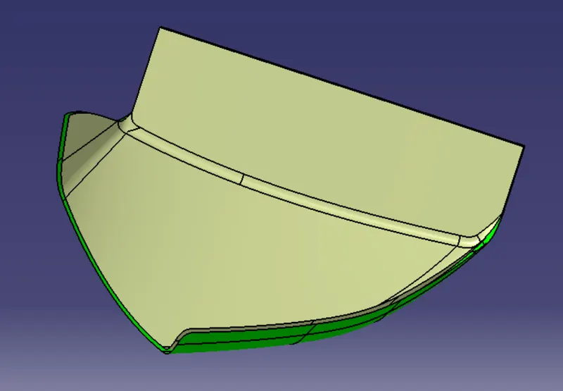
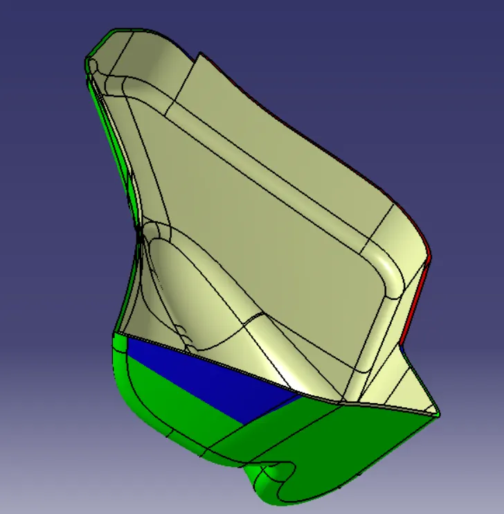
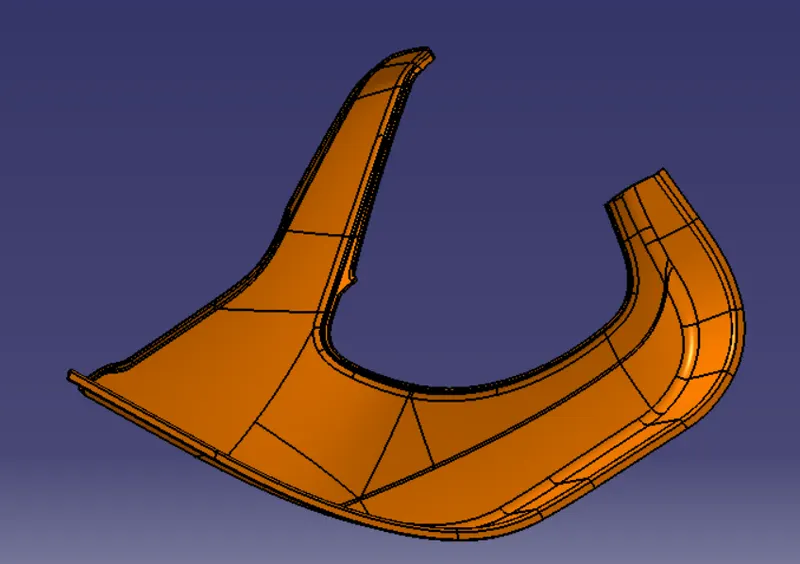
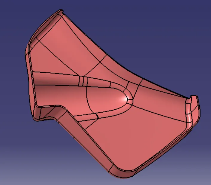
Class B is the rear side of the part which holds the mounting features and gives thickness to the panel in this case the thikness is 2.5mm.
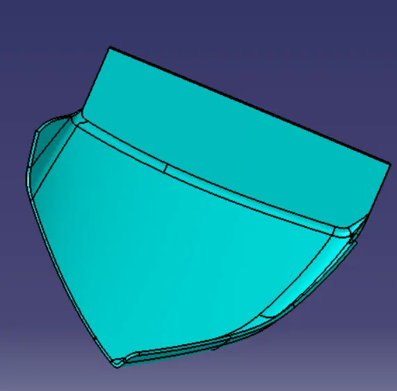
Class C Surafce and Solid Bodies:
Mounting Features:
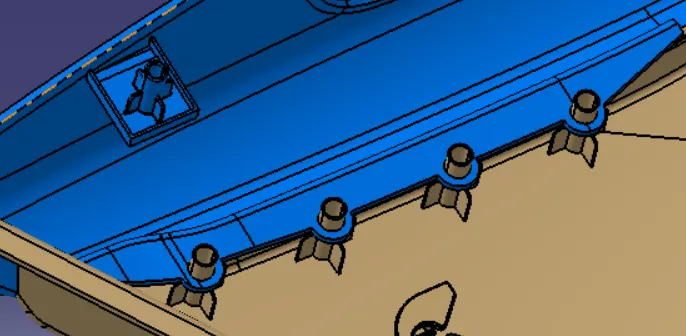
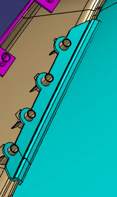
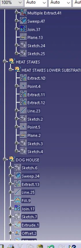
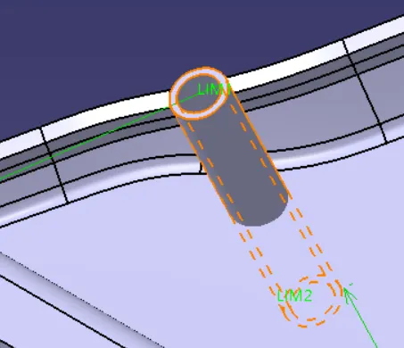
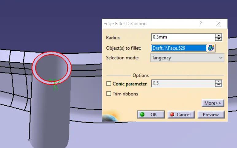
1. Heat Stakes:

2. Gussets:
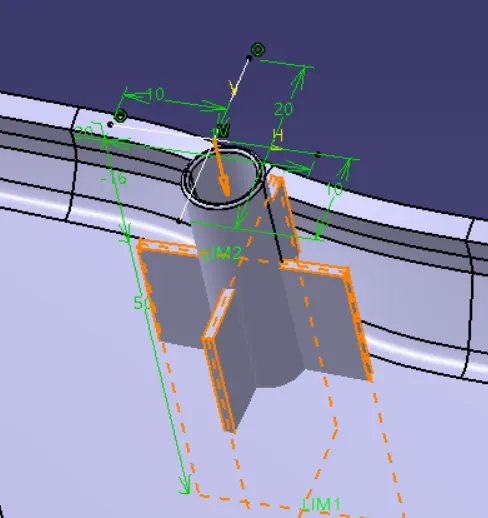
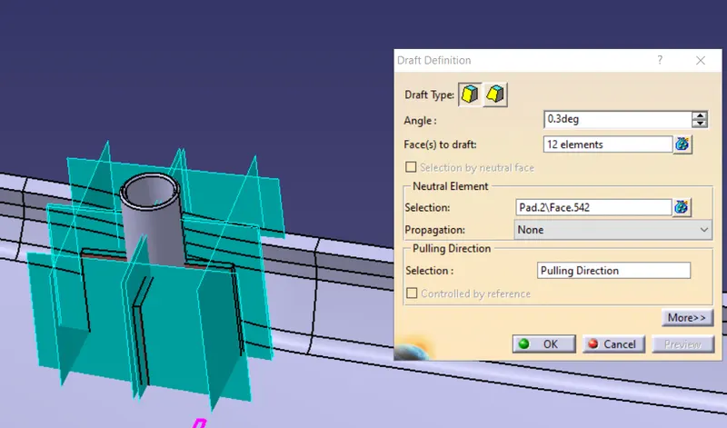
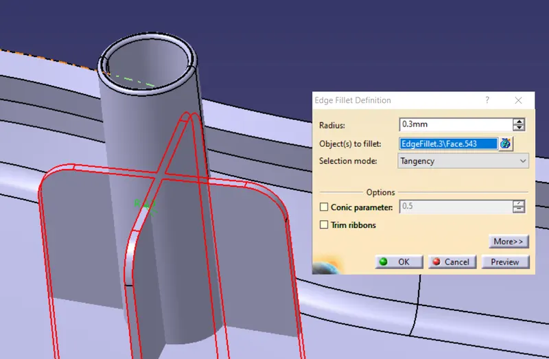
Gussets are rib like features that add support to structures such as bosses, ribs, and walls. As with ribs, limit gusset thikness to one half to two thirds the thikness of the walls to which they are attached if sink is a concern.
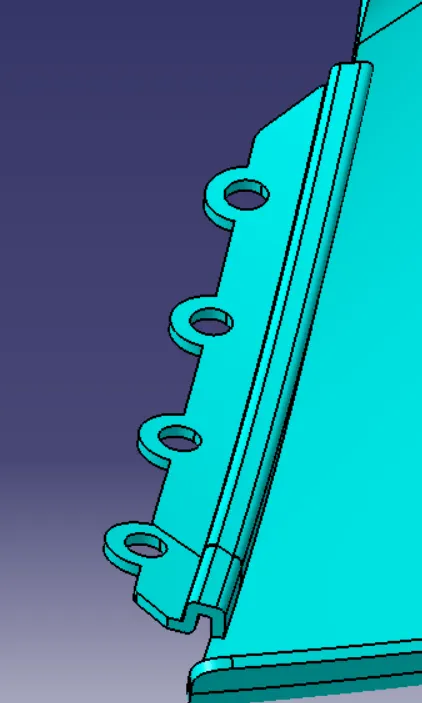
3. Holes On Flanges For Fixation:
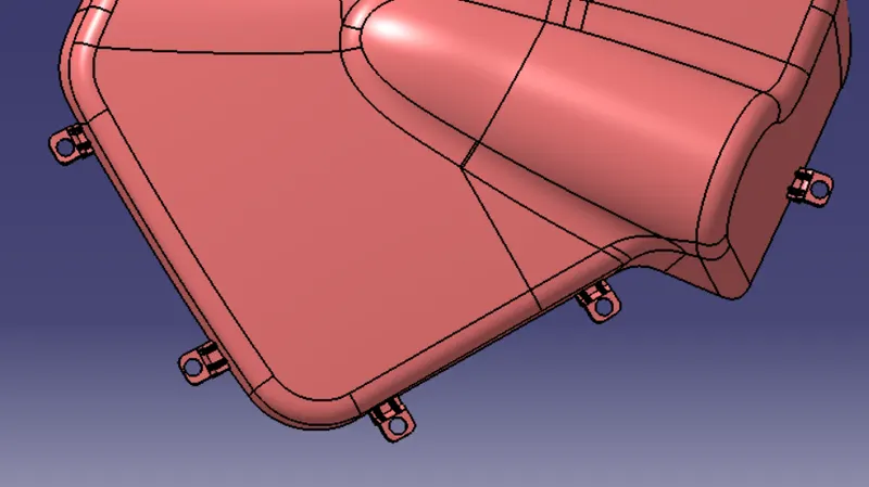
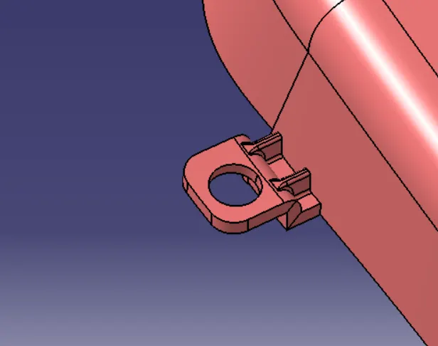
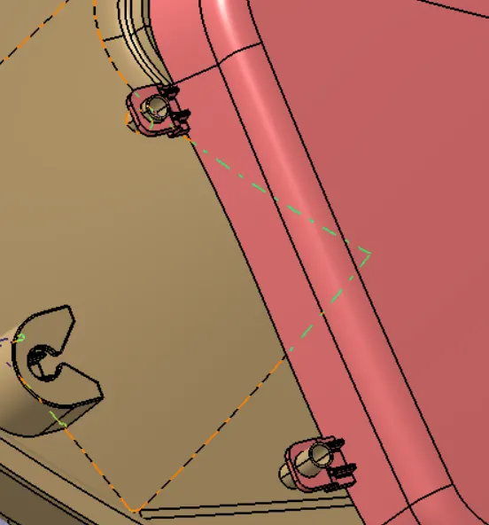
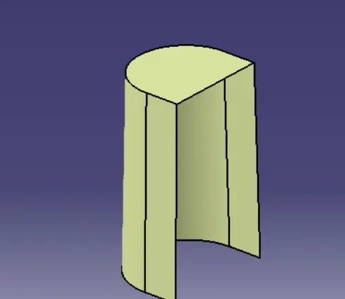
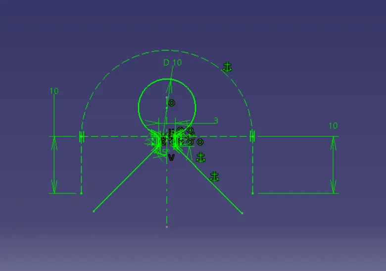
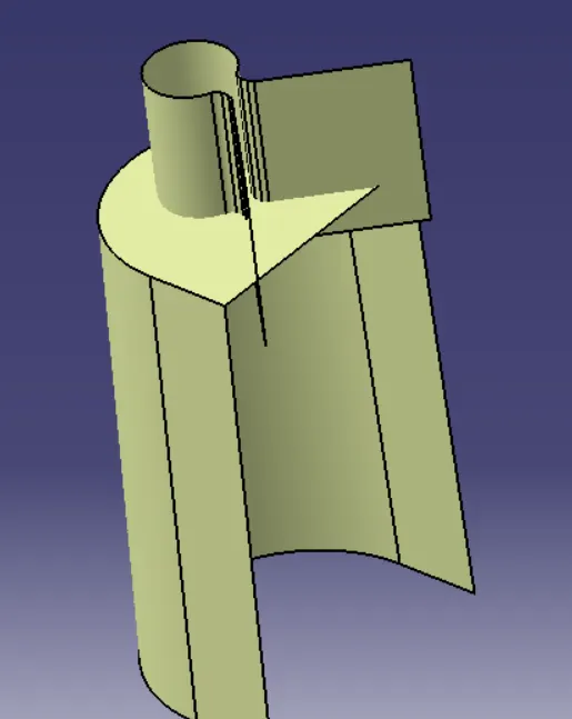
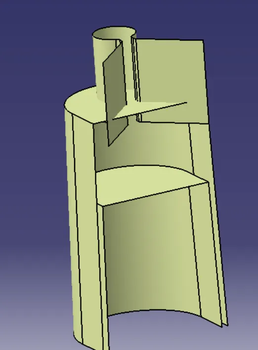
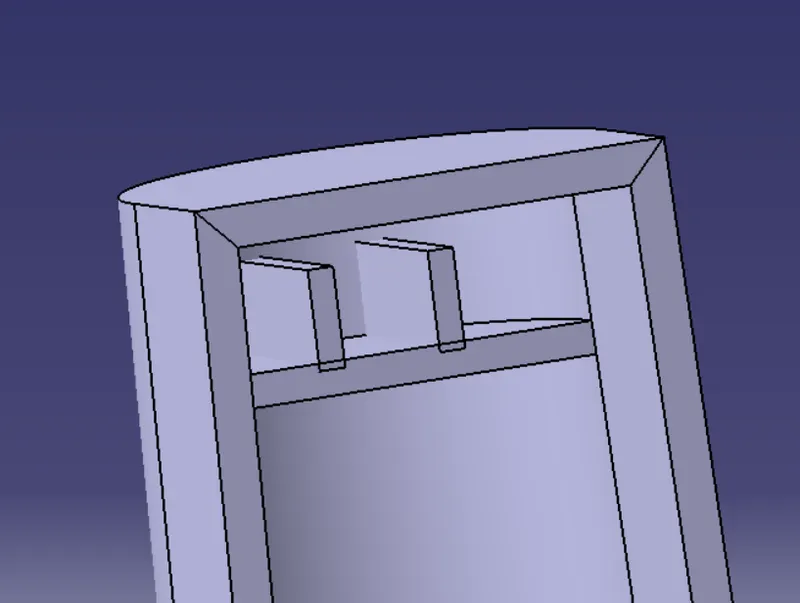
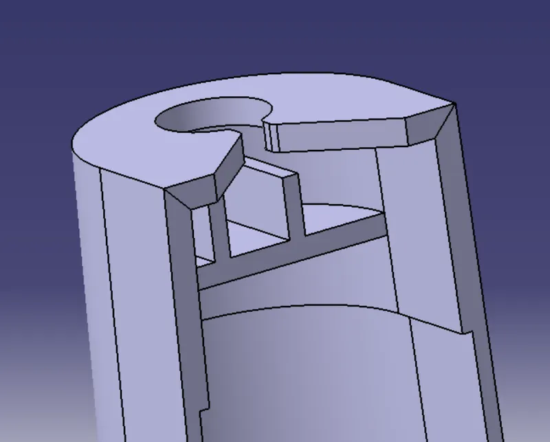
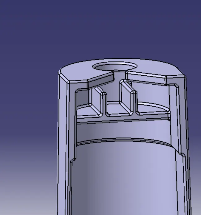
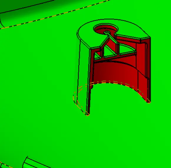
4. Dog House:
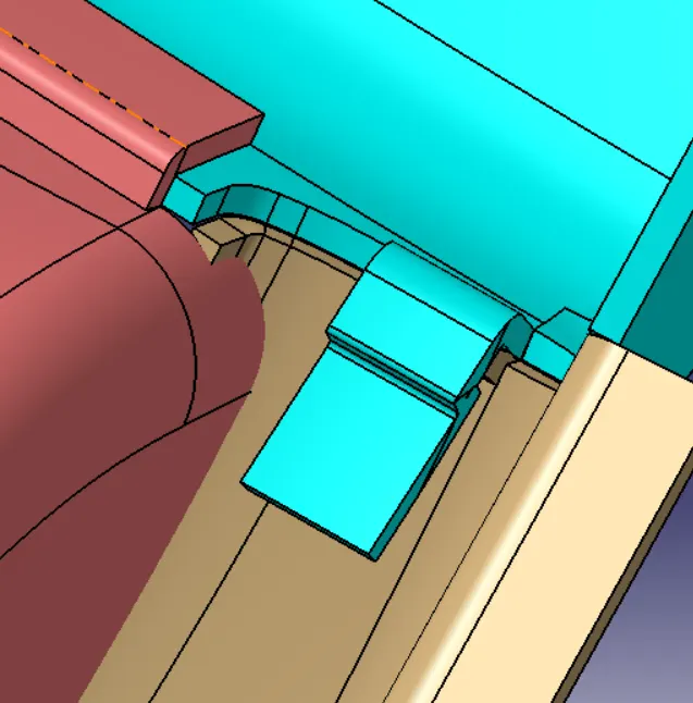
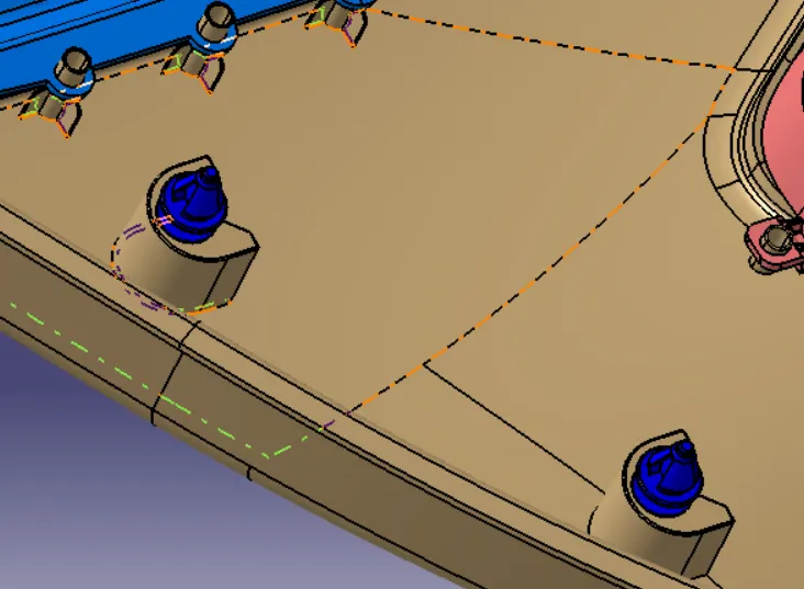
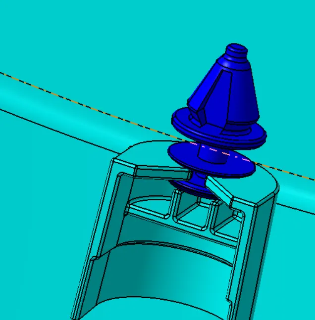
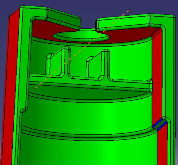
Dog House is an engineering feature used in plastic trim design. Dog Houses are used as a supporting feature. Sometimes other engineering features like snaps, locators etc. are mounted on them to increase their strength.
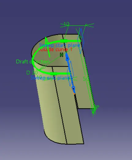
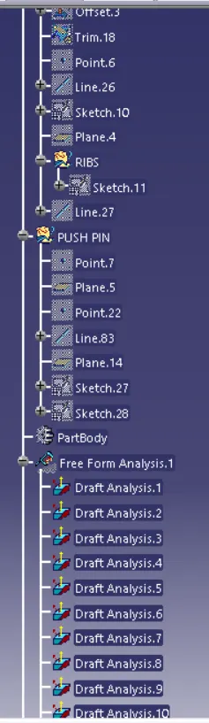
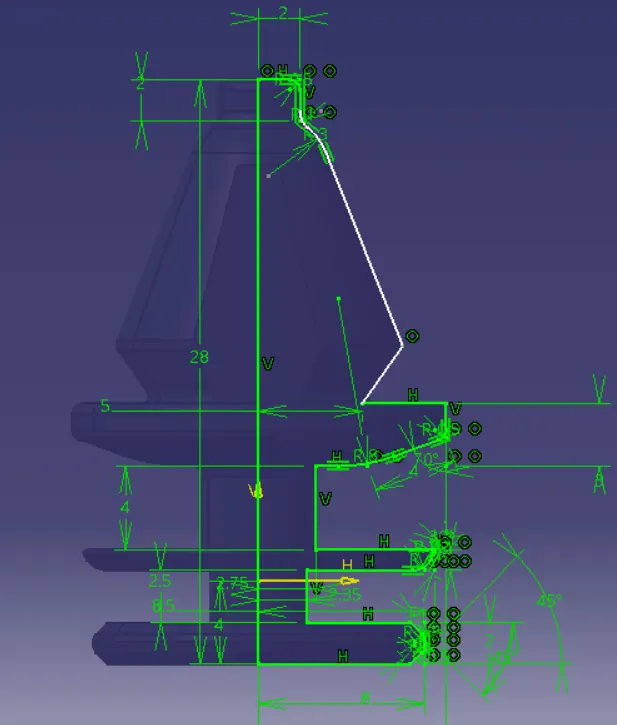
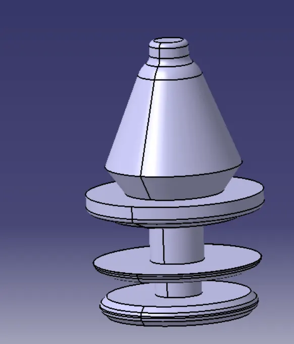
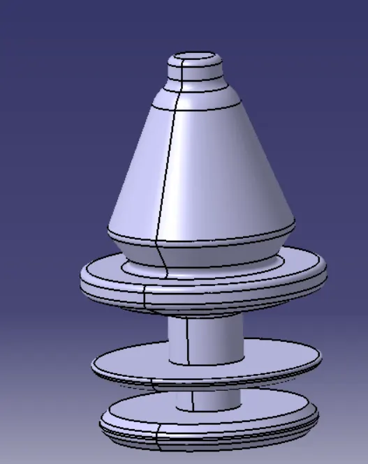
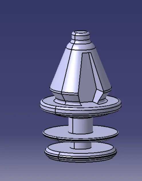
5. Push Pin:
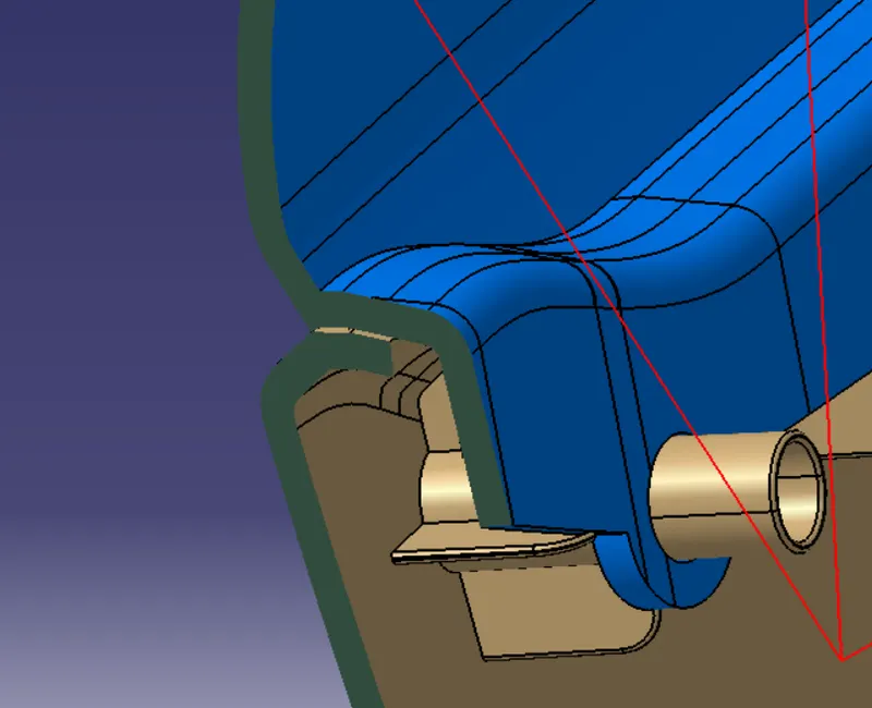
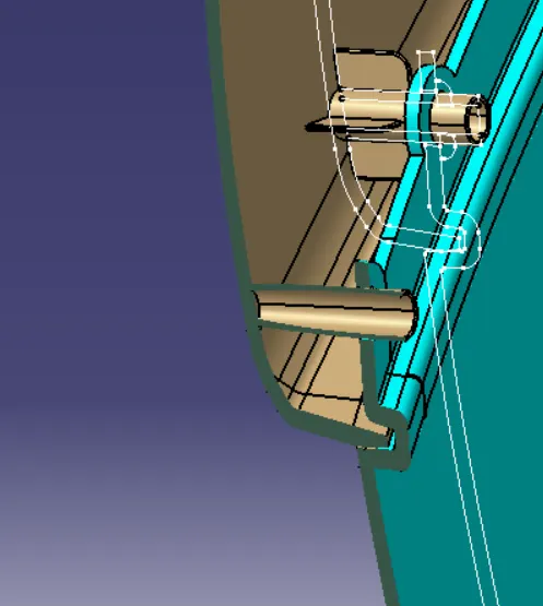
Pushpin helps us in locating and arresting components of an Assembly and it provides alignment in mating parts
and it also act as a stopper or guide for various mechanisms.
DRAFT ANALYSIS:
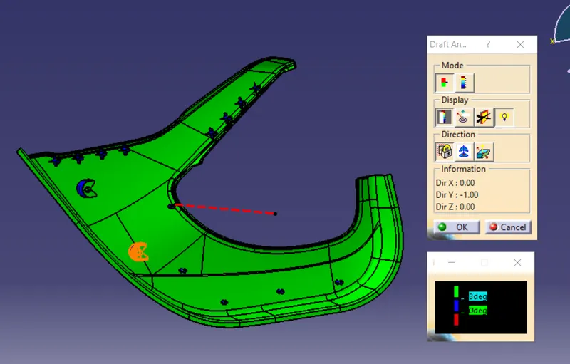
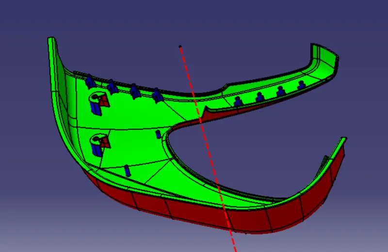
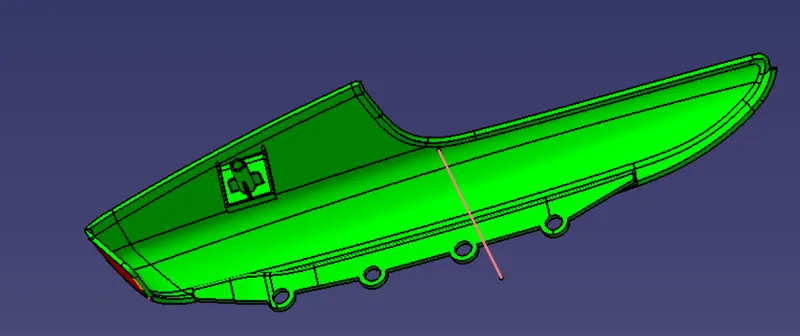
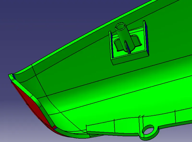
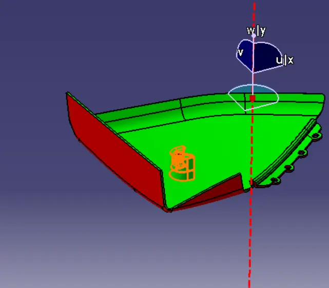
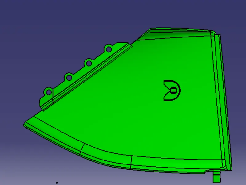
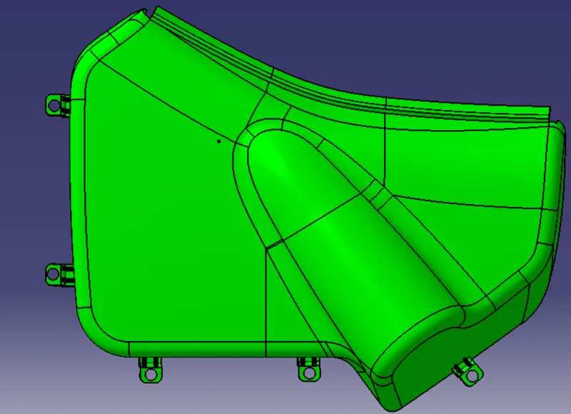
Draft Analysis is used to check whether the minimum 3 degree draft is maintained. If the minimum 3 degree is provided then the whole part is turned into green.
The part created has to be changed to material mode in display frame. Then by enabling compass definition the axis system is pan along the direction of the part and aligned in line with the tooling direction.
Lock Direction is applied that fixes the compass and then the mode dialog box is formed by snapping at any point on the part The Color Codes are classified and Draft Angle are applied.
Then the Running point analysis is used to hover around the part to analyze the permissible draft angles and the analysis is saved.
1. Lower Substrate:
2. Arm Rest 1:
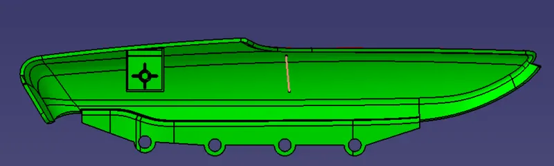
3. Arm Rest 2:
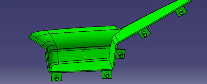
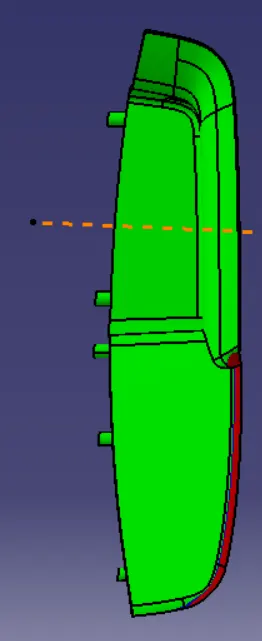
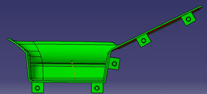
4. Map Pocket Upper:
5. Map Pocket lower:
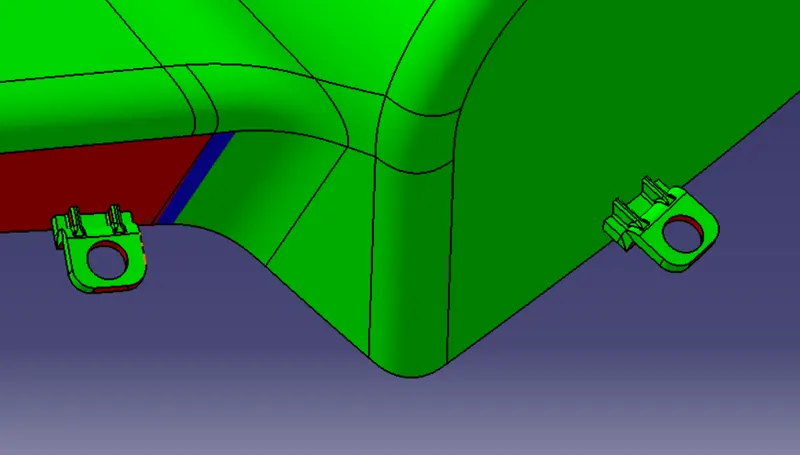
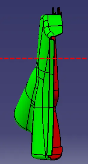
Dog House:
ASSEMBLY OF PARTS: