Advanced Sheet Metal Design Using NX Cad Challenge_6_Bracket
BRACKET
Objective:
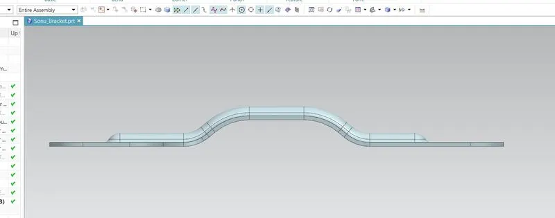
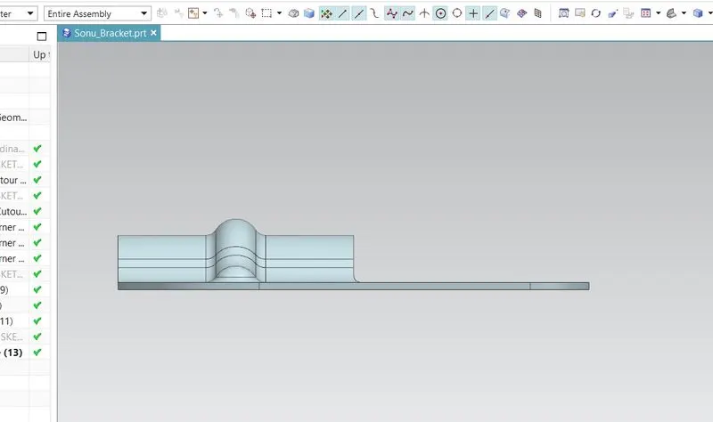
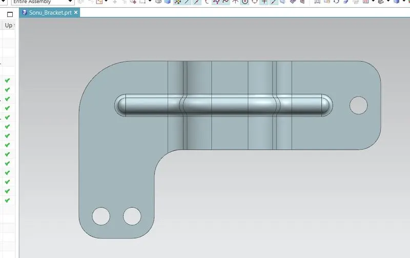
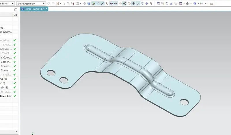
To design Sheet Metal Bracket using Siemens NX Sheetmetal Application.
Introduction:
The sheetmetal application provides an environment for the design of sheetmetal parts.
Design Approach:
Workflow to design the Sheet Metal Bracket.
1. Sketch the 2D shape of the Bracket
2. Construct the Base feature using Tab command.
3. Add feature such as beads.
4. Unbend the part and add other features such as dimple, hole, cutuots etc.
5. Rebend the model.
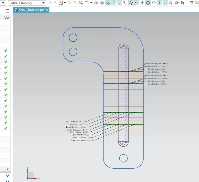
6. Create a flat pattern
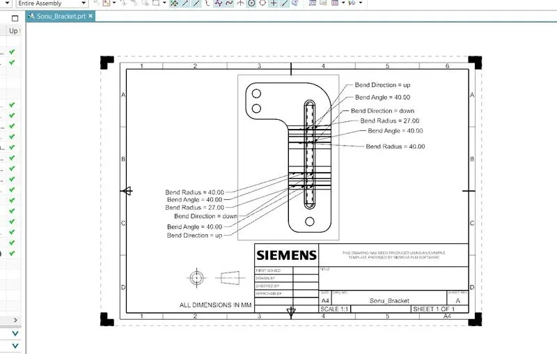
7. Create a drawing Sheet.
Description:
Features used to design Sheet Metal Bracket.
1. Sketch:
This command is used to create the 2D sketch of the casing.
2. Contour Flange:
this command is used to create a flange by extruding a sketch along a vector, or by sweeping a sketch along an edge or a chain of edges,
3. Normal Cutout:
This command is used to create the cutout to the material by projecting a sketch onto the model and then cutting perpendicular to the faces intersected by the projection.
4. Break Corner:
This command is used to round or chamfer the sharp corners of a tab or flange.
5. Unbend:
This command is used to unbend or flat material to add some more features.
6. Bead:
This command is used to lift the material along the contour of a sketch that simulates a stamping tool.
7 Rebend:
This command restores an unbent feature to its previous bent state, along with any features added after the unbend feature.
8. Hole:
This command is used to create hole in the part with standard values.
Conclusion:
1. Sheetmetal Bracket is created using NX sheetmetal application.
2. Detailed drawing sheet and standard views are made and attached.
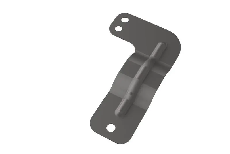
3. The model is rendered using NX ray traced studio.