Week 8 - Challenge 2 - Base Bracket Design
AIM
To create Base Bracket Plastic component from given Class A surafce . For that Tooling Axis of given Class A surface shoul be created obeying all the rules of drafgt angle and finish with perfomingdraft analysis.
OBJECTIVE
1) Checking continuity of class A surface.
2) Testing possible tooling direction and creating tooling axis.
3) Performing draft analysis.
4) Creating Class B surface from Class A .
5) Creating Class C surtaface to join A & B surafce.
6) Creating solid features by using closed surafce.
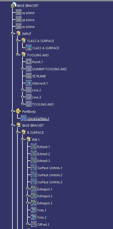
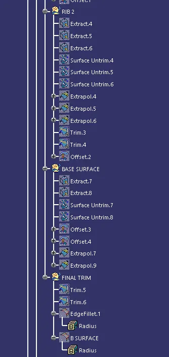
7) Maintaining proper tree structure and naming geometrical sets according to their properties.
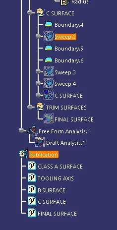
8) Publishing all the surfaces and tooling axis.
PROCEDURE FOLLOWED
Step-1
CLASS A SURFACE:- It is outermost surface of automobile which gives aesthetic look to vehicle. It is physically touchable. It is obtained from clay modeling by reverse engineering. This surface is given to plastio product designer too work.
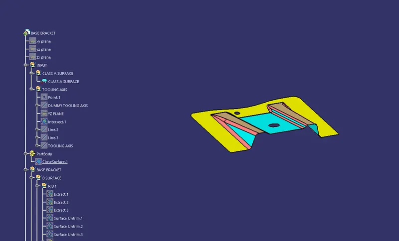
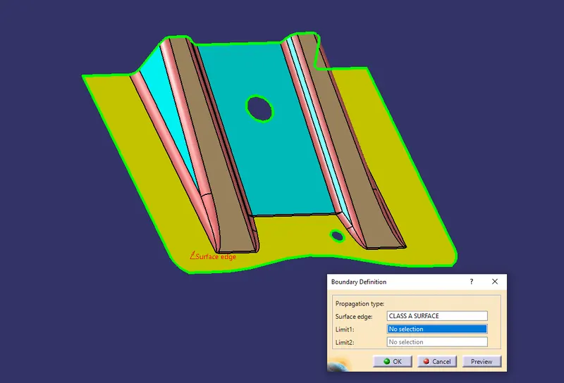
Import the class A surface to CATIA V5. Then do a continuity test on the model for making sure the surface is properly joined using boundry command.
Step-2
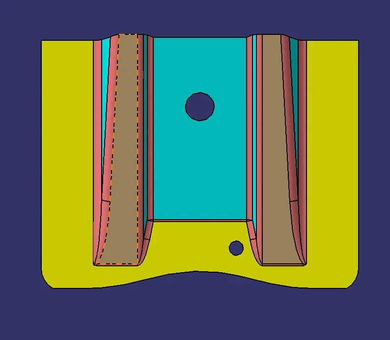
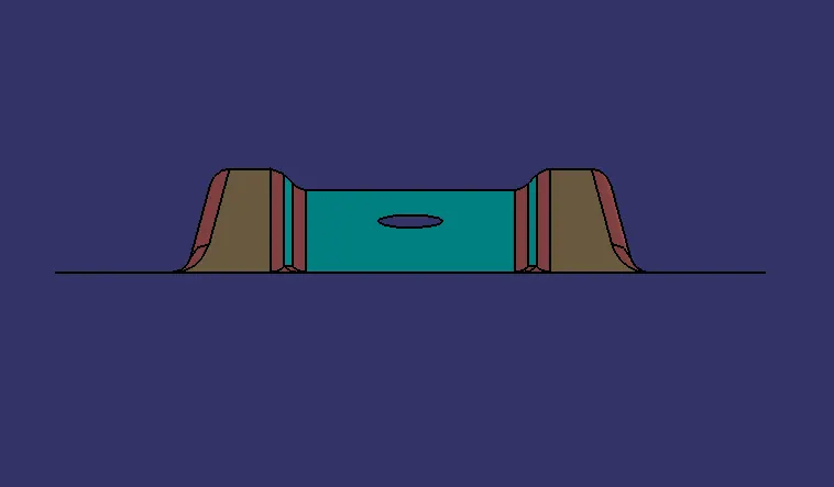
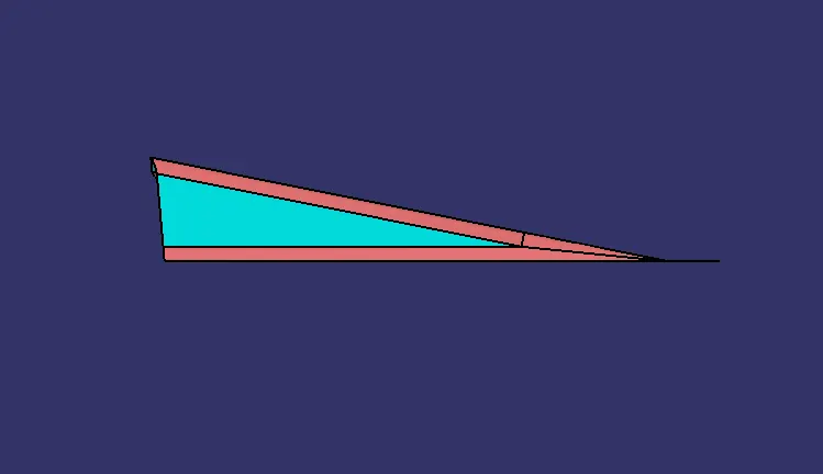
Next analyze tooling direction for the class A surface. From visually as shown below X & Y directin is not clearing the two holes at its top. As rules suggest tooling direction should be clearing these two holes on the surface. But in Z direction it is clearing both the holes and flat surface.
Step-3
TOOLING AXIS:- vIts is the direction in which core and cavity opens and closes.
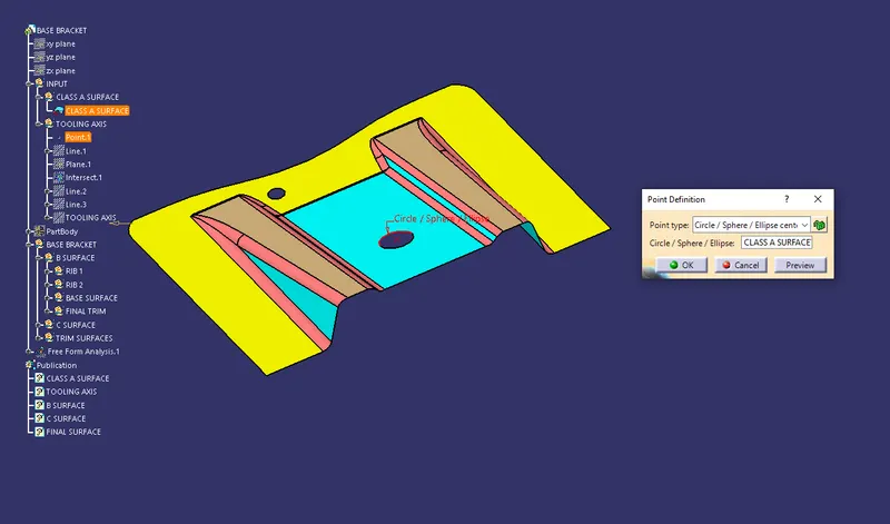
Create a point take one of the centered hole on the class A surface for tooling axis .
Step-4
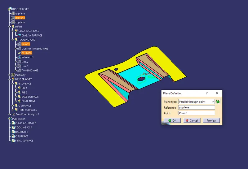
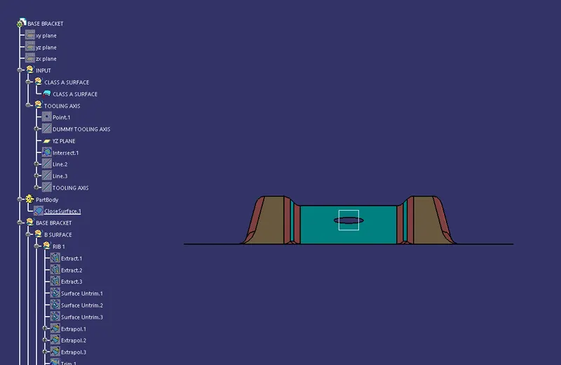
Create a plane in YZ plane take the point as reference for creating tooling axis in Z direction.
Step-5
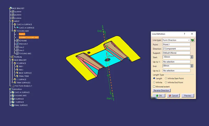
Now create a dummy tooling axis for reference.
Step-6
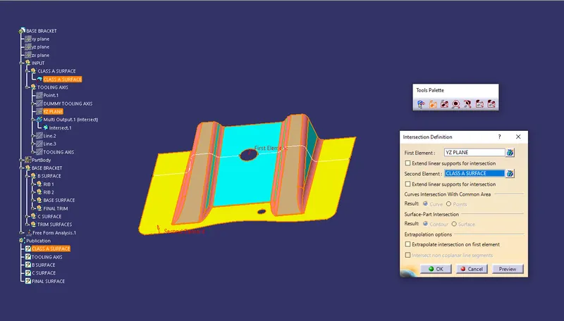
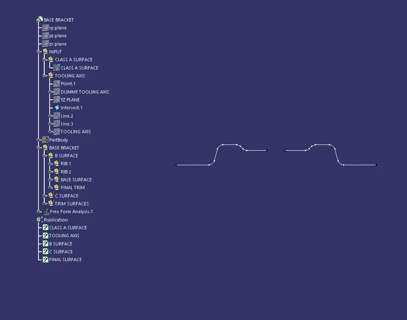
Take intersection of YZ plane with class A surface. We will get the two curves.
Step-7
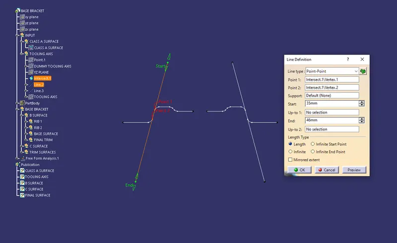
Now we have to see which surface will create problem or will bw difficult for tooling. So make two lines from them using point to point in line commmand for creating tooling axis.
Step-8
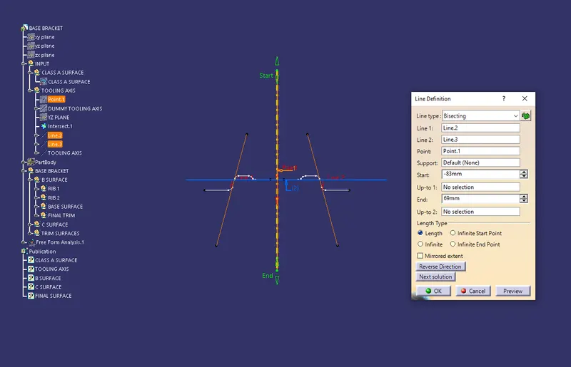
Using Both the lines from before create bisect in line command to create Tooling axis.
Step-9
Draft analysis
- To perform draft analysis Go to Menu bar > insert > Analysis > Feature Draft Analysis.
- Switch customize view parameters mode to select material.
- Click on compass icon and align it with the tooling axis and click on the surface, we will get the results.
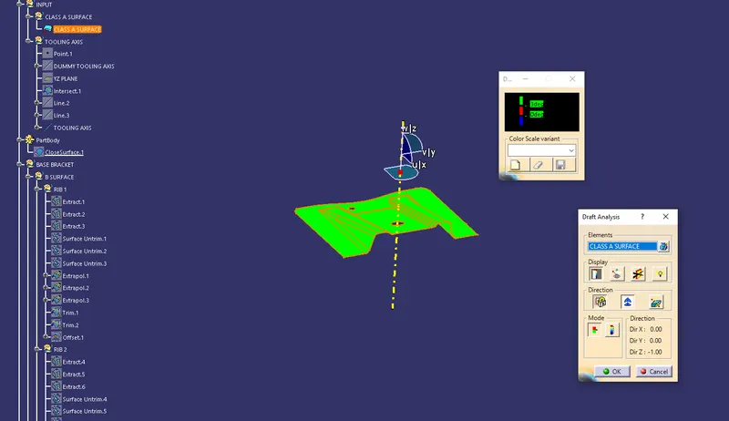
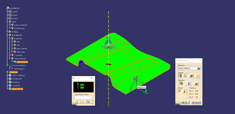
- FRrom below image it is seen that surfaqce in green color has more than 3 degree draft which is most required for tooling feasibility.
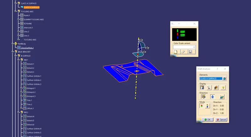
By inversing draft direction we see below image.
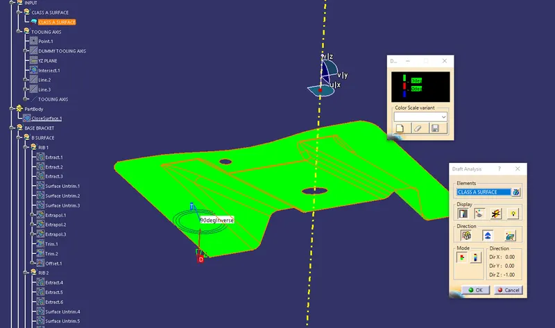
Below image shows runnig point draft analysis.
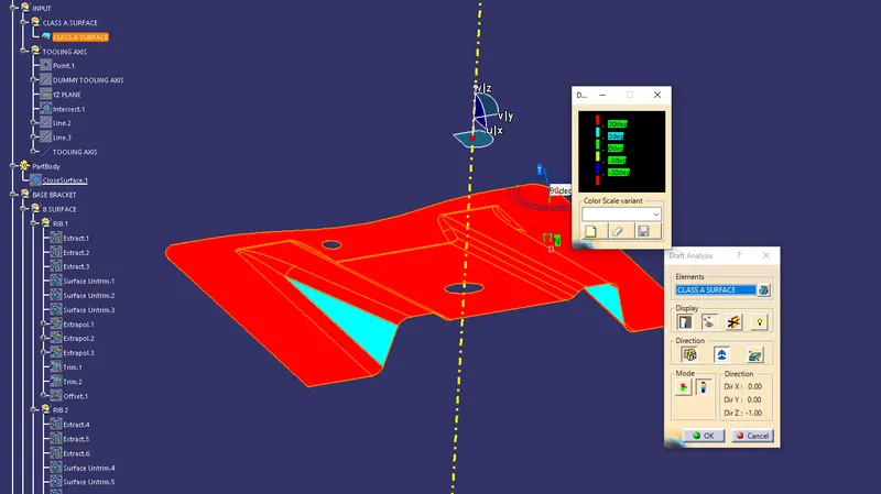
Below image shows full draft analysis.
Step-10
CLASS B SURFACE:- This surface is created by taking offest from class A surface. It is surface on which all engineering featurer like screw bossesw, dog house, ribs and mounting are created.
Now Creating class B surface from given class A surface. For creating a clsss B surface first we have to do is extract the following surfaces from class A as shown below.
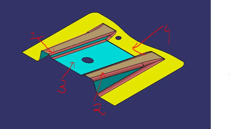
Step-11
First step extract the Rib part from the class A surface.
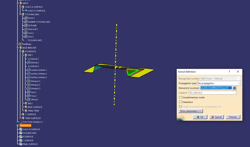
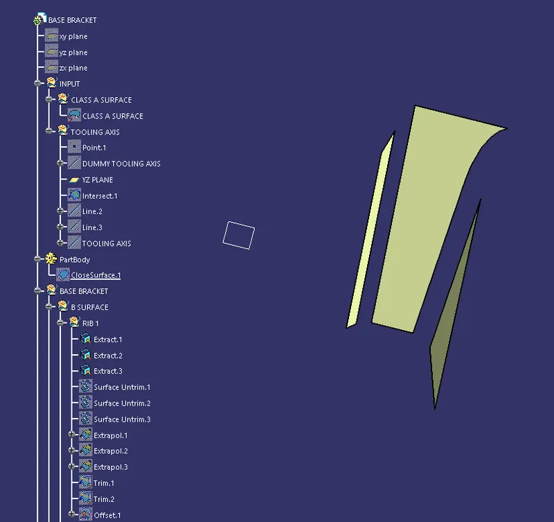
Step-12
Then Surface Untrim the extracted Rib from the class A surface.
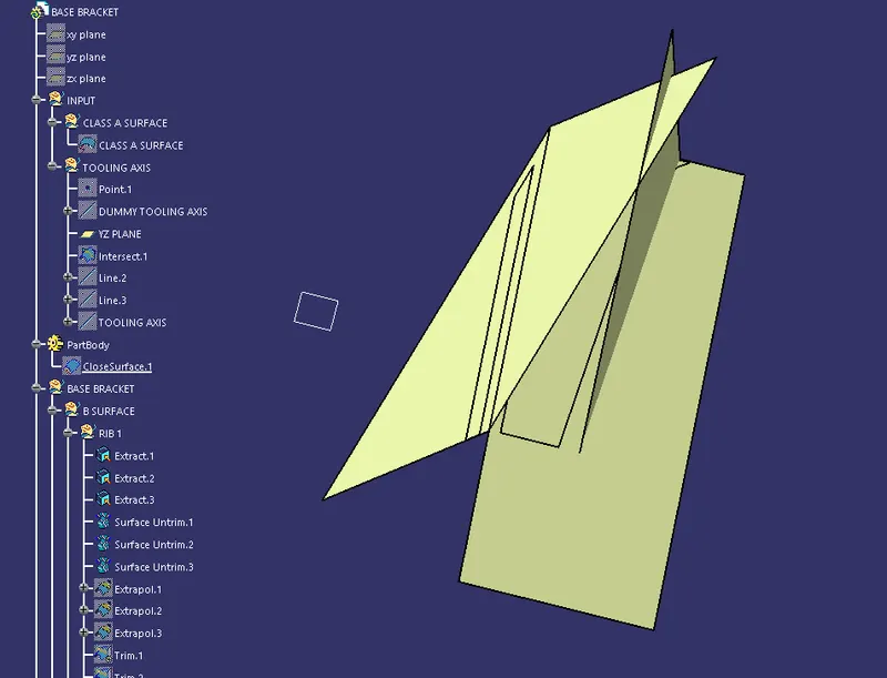
Step-13
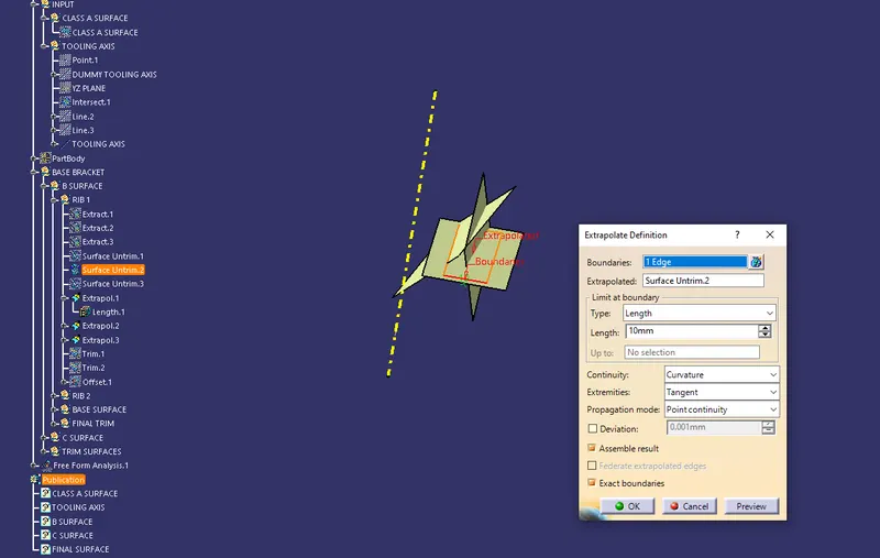
After this extrapolate the Rib surfaces to a lengtrh of 10 mm as shown below.
Step-14
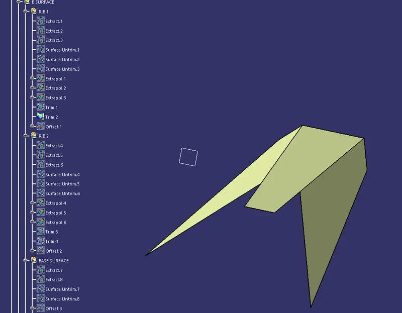
Then each surfaces with each other to get the rib as shown below.
Step-15
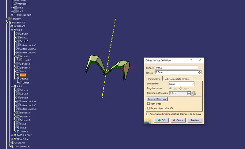
After following similar steps as before for other Rib also and offset them toward negative Z-direction by 2.5 mm.
Step-16
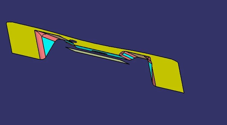
Follow Similar steps like( Extract, Untrim, Extrapoplate by 10mm) for Flat surface and Slant surface and offset them by 2.5mm.
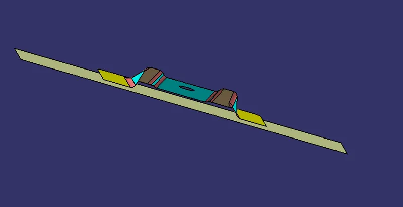
Step-17
Now Final Trim both the ribs with the Flat and Slant offset surfaces to get Class B surface as shown below.
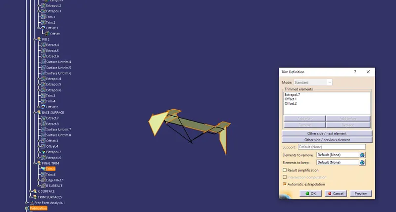
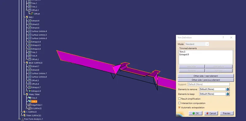
Step-18
This final trim is our inner surface so fillet edges of this surface as per formula,
Fillet radius = Class A surface fillet value + Part Thickness
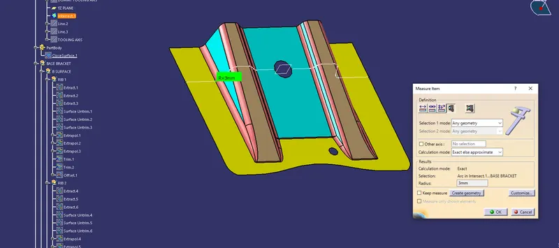
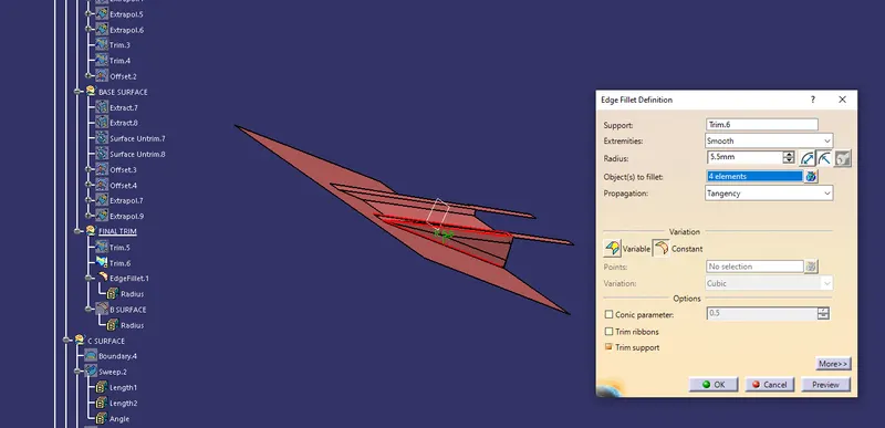
Step-19
CLASS C SURFACE:- This is surface which joins classs A and class B together.
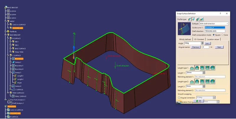
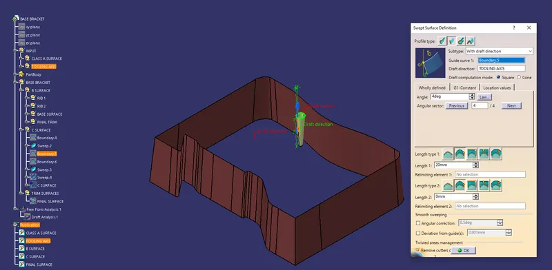
Next step is creating Class C surface to join A & B class surface. For that first create a boundry using boundry command of the class A surface edge and edges of the holes.
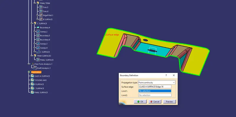
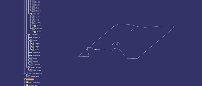
Step-20
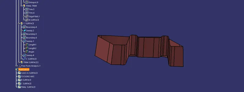
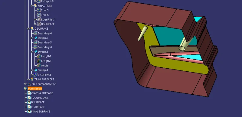
For creating Class C surface go to Sweep command > Line > with draft direction. Then take boundry as guide curve and Tooling axis as draft direction also draft angle to create class C surface from edges of class A surface and holes as shown below.
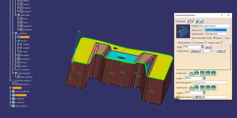
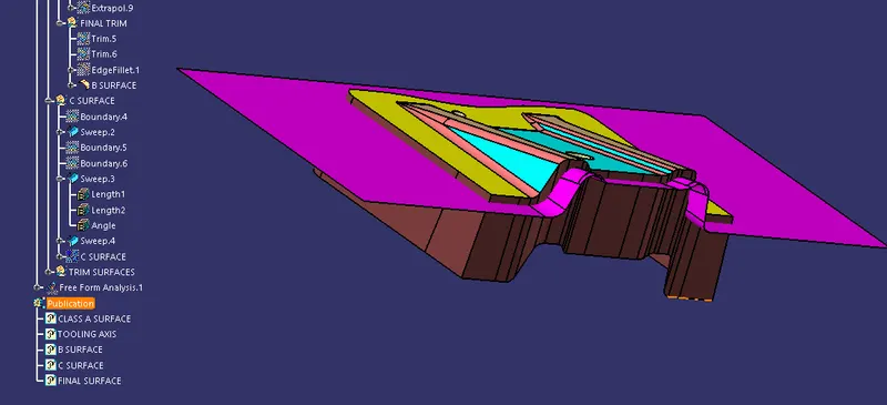
Step-20
Now join the class A surface and class C surface together using join command as shown below.
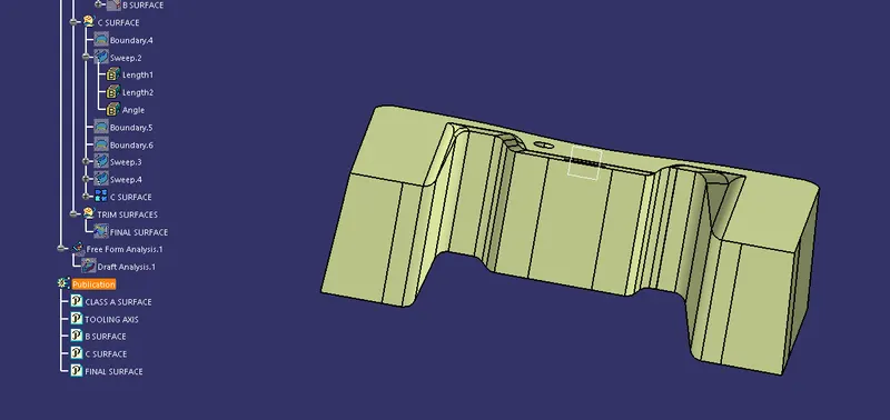
Step-22
Final trim the class B surface with joined surface created earlier.
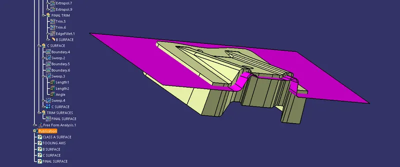
Step-23
After trimming we get final base bracket with close surface.
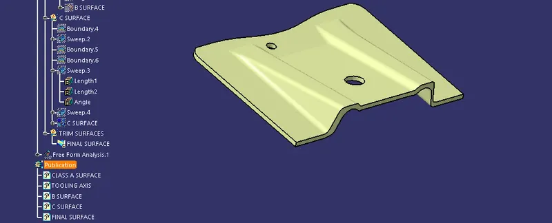
Step-24
Perform Final draft analysis on the close surface achieved earlier to make sure proper draft angle which meets the requirement of the molding.
Step-25
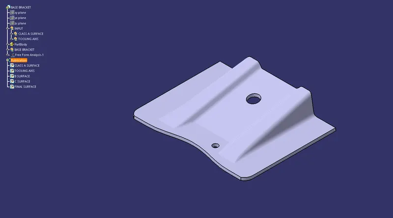
Make a solid body out of the close sureface.
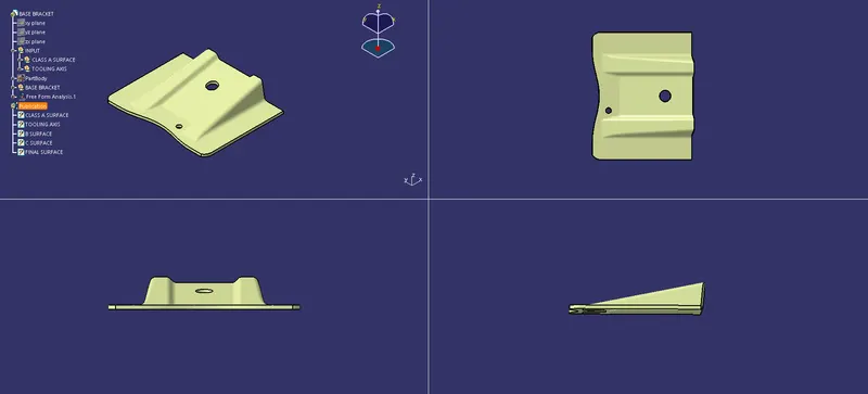
VIEWS(ISOMETRIC, FRONT, TOP, SIDE)
TREE STRUCTURE