Roof challenge
AIM
Design of Car Roof with all its component such as Rear Roof Rail, Bow Roof, Center Roof Reinforcement and Rear Roof Rail. Also its calculation for Heat Distortion Criteria, Snow Load Criteria and Draft Analysis.
INTRODUCTION
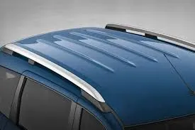
An automobile roof or car top is the portion of an automobile that sits above the passenger compartment, protecting the vehicle occupants from sun, wind, rain, and other external elements. Because the earliest automobiles were designed in an era of of horse drawn carraiges early automobile roofs used similar materials and designs.
In later years, many variations on the automobile roof developed. These include:
- Convertible roofs
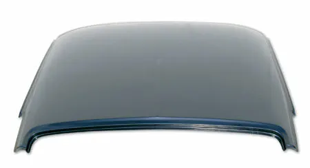
- Hardtop roofs
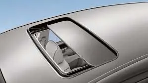
- Sunroofs
- T-tops
- Targa tops
- Vinly Roofs

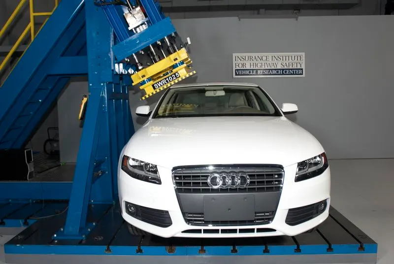
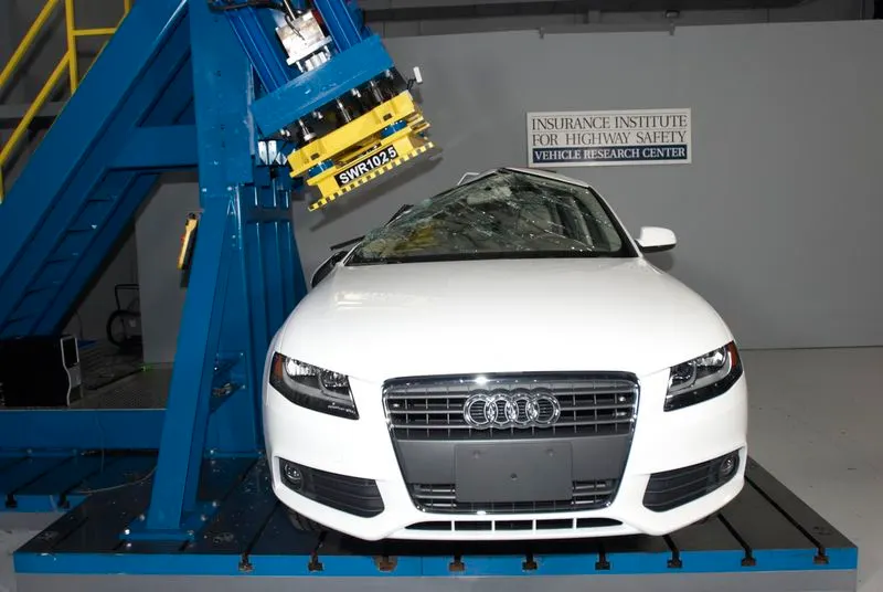
Car Roof Crush Test:
Therefore, passenger safety is also a very important parameter in front of OEMs. For this reason, strength is a very important criteria for designing a vehicle roof.
The strength of the roof structure to occupant the protection in real world crashes, requiring the maximum moving distance of the roof structure should be less than 127mm when the induced load is 1.5 times the vehicle weight.
For the test, the passenger car shall be rigidly placed or positioned on horizontal surface with the doors locked and the window closed.
This test can be conducted on either side of the roof structure, the front left or front right side but not on both sides in one single test and still meet the requirements of the test. The rigid plate shall not move faster than 0.5 inches/second and the force applied on the plate shall not exceed the lesser of 1.5 times the unloaded vehicle weight (UVW) expressed in kilograms multiplied by 9.8 or 5000lbs
Also, the direction of the forces shall be downward and perpendicular to the lower surface of the rigid plate and such that moves in a straight line without rotation. The duration of the test shall not exceed 120 seconds. The longitudinal axis of the plate is pitched forward at a 5° angle as viewed from the side of the passenger car.
Rollover accidents of a car are the most occurring accidents that we see in our daily lives. The passengers experience major injuries like neck, head and spine injuries. So, to reduce the injuries of a passenger from major fatalities it is important to provide safety in the car. Though safety is provided by seat belts and airbags during accidents, the passenger must have sufficient space for survival in the car during accidents. The roof of the car must have high strength to resist the crush force to avail the passenger some space for survival. Therefore, in this project, we have carried out roof crush test using Federal Motor Vehicle Safety Standards (FMVSS216) standards in LS dyna software. We have used Hyper mesh software to mesh the model and to apply boundary conditions to it. And the rigid plate is used to crush the car roof as specified by FMVSS216 standards. The rigid plate is oriented on the car roof as specified by Insurance institute of highway safety (IIHS). And an alternate material is used to the car roof structure to the baseline model to check the crashworthiness of new material. The outcome of test results of the new material's strength to weight ratio (SWR) was compared to baseline model and the new material is proposed for the roof (B-pillar) which is found to be more crashworthy.
Stamping Process:
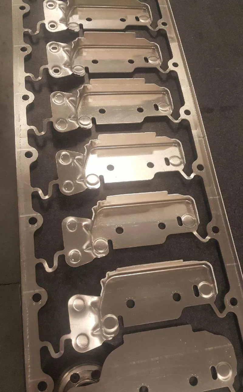
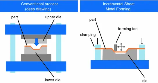
The process of turning sheets of metal into a useful part or component is called sheet metal stamping. The metal is fed into a press, where the stamping tool, also known as a die, creates the desired shape. The die is pressed into or through the metal with tremendous force. The force used in the process is measured in tons.
Common sheetm metal stamping process:-
There are basically only three components to sheet metal stamping—the sheet metal, die, and press machine—but any single part can require multiple steps to arrive at its final form. The following guide explains a few common processes that might occur during metal stamping.
- Forming: Forming describes the process of transforming the flat metal into another shape by applying force. It is accomplished in one of several ways, depending on the design specifications for the part. With a series of operations, the metal can be altered from a relatively simple shape into a complex one.
- Blanking: Blanking is the most basic technique and initiates when the sheet or blank is fed into the press where the die cuts out the desired shape. The resulting piece is called a blank. The blank may be the desired part, also known as a fully finished blank, or it may continue to the subsequent step of forming.
- Drawing: Drawing is a more complicated operation and is how vessels or deep depressions are formed. Tension is used to carefully draw the material into a cavity to change its shape. Though the material might stretch while it’s drawn, technicians try to avoid stretching as much as possible to keep the material intact. Sinks, cooking equipment, and oil pans for vehicles are usually made with drawing.
- Piercing: Piercing is almost the opposite of blanking, but instead of saving the blanks, technicians use the material around the outside of the punched area. As an example, think of cutting biscuits from a rolled-out circle of dough. During blanking, the biscuits are saved; during piercing, on the other hand, the biscuits are discarded, and the hole-riddled remains are the desired outcome.
Materials:
Though virtually any metal, including gold, can be stamped, sheet metal is by far the most common. The type of metal used depends on the type of part that’s needed and its desired properties, such as corrosion- and heat-resistance.
Sheet metal stamping can produce parts from the following materials:
- Stainless steel
- Low- and high-carbon steel
- Aluminium
- Titanium
- Brass
- Bronze
- Copper
- Inconel
- Nickel alloys
ROOF COMPONENTS
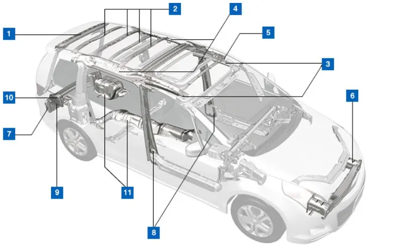
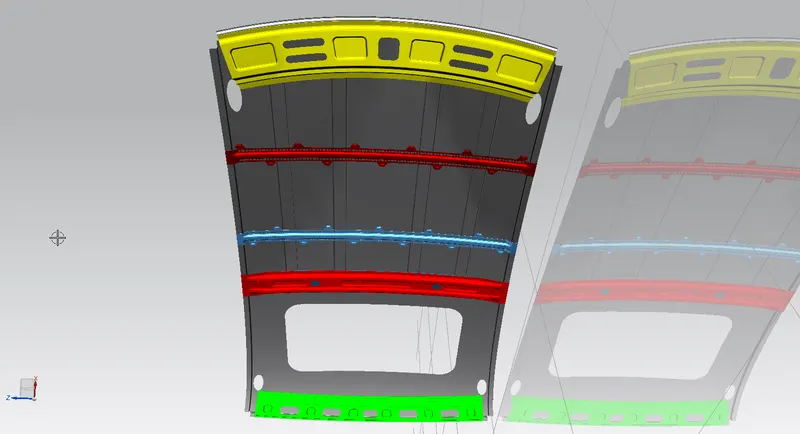
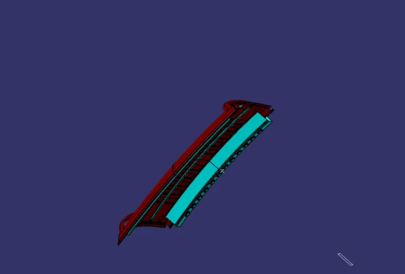
Roof Consists of components such as :
- Front Roof Rail
- Bow Roof 1 & 2
- Center Roof Reinforcement
- Rear Roof Rail
Design considerations for a roof:
- Visibility criteria
- Head clearance
- Curvature study
- Heat distortion and snow load criteria
- Draft analysis.
DESIGN OF ROOF
Step-1
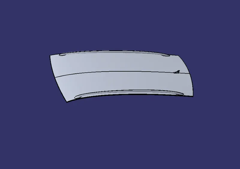
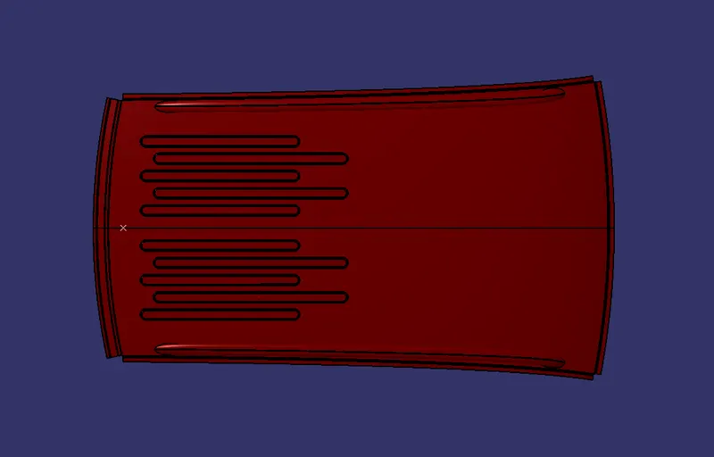
- The styling team has provided the solid dump outer panel from that we are extracting the surface to model the necessary reinforcements like Ditch area, Front Roof Rail, Bow Roof Rails and Rear Roof Rail.
Step-2
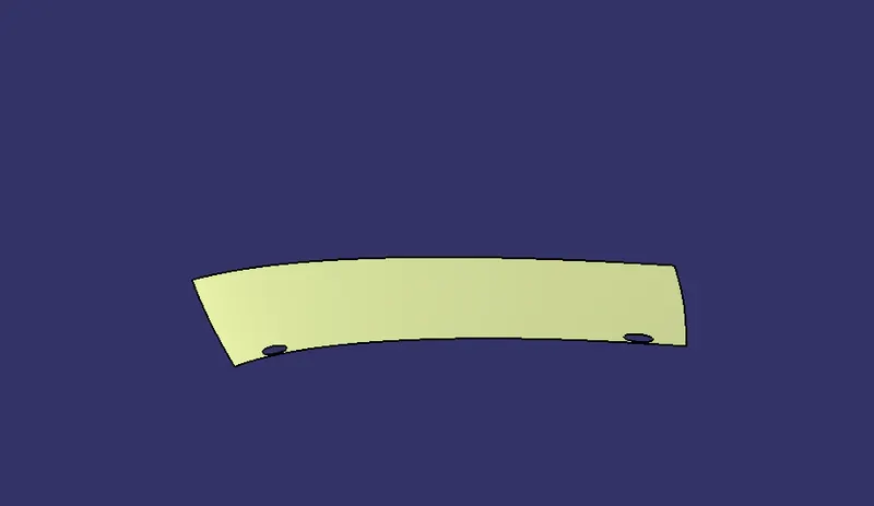
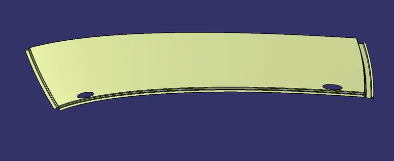
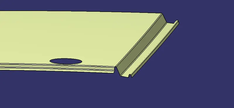
- Extract the Surface and work on Flanges of the Roof.
Step-3
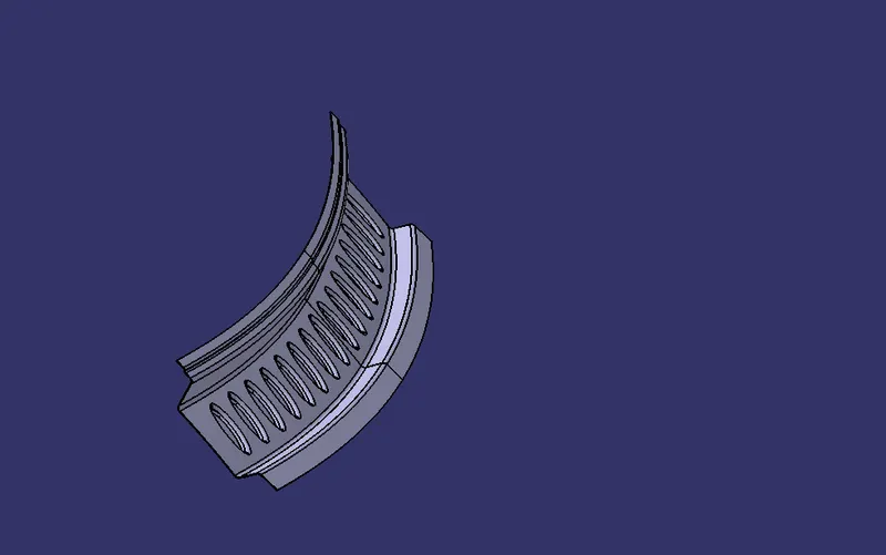
Design Of Front Roof Rail
- Given Master Section for refrence
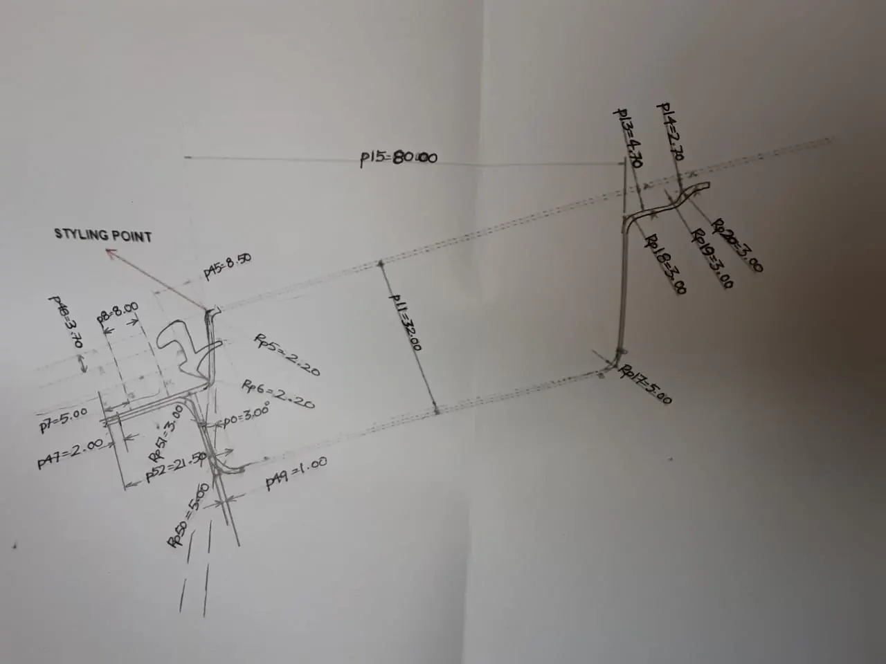
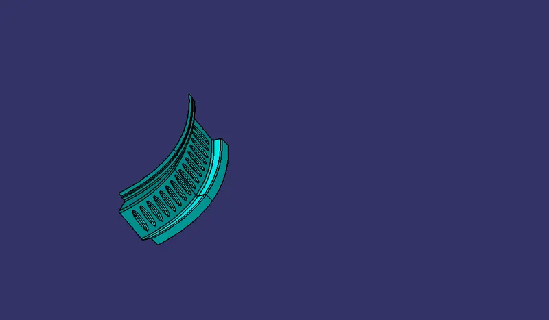
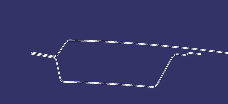
- Front roof rail is the one which joins the wind shield glass, body side outer and the inner panel also. Here the front roof rail is designed based up on the master section given.
Step-4
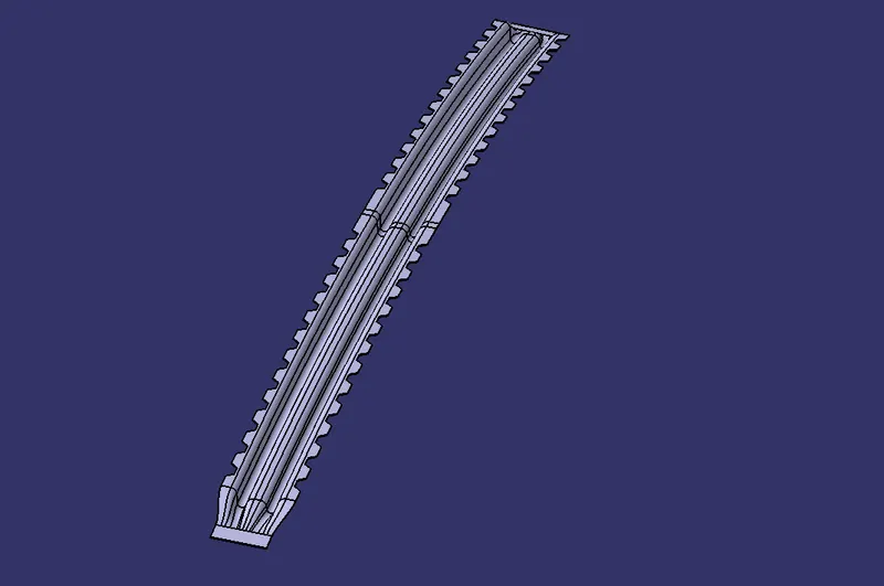
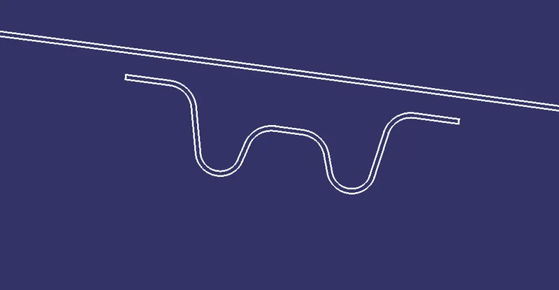
Design of Bow Roofs
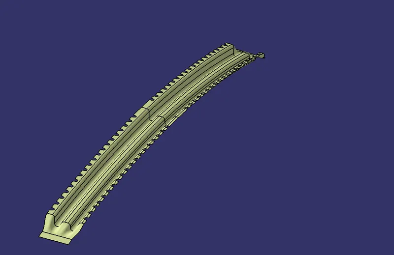
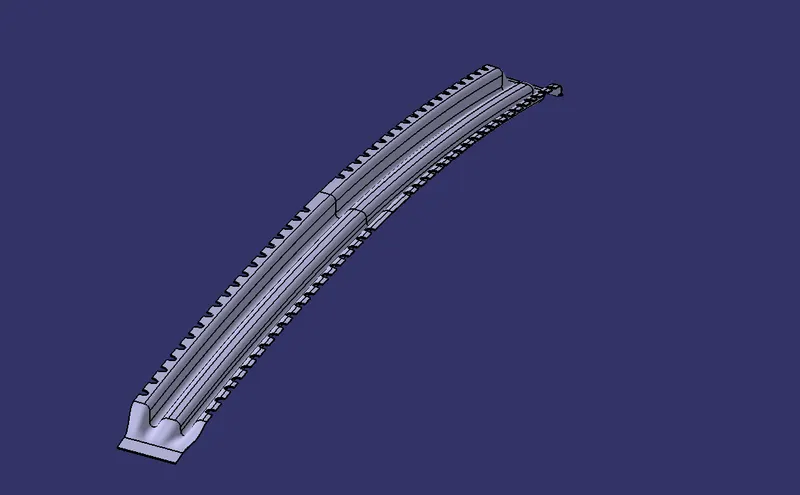
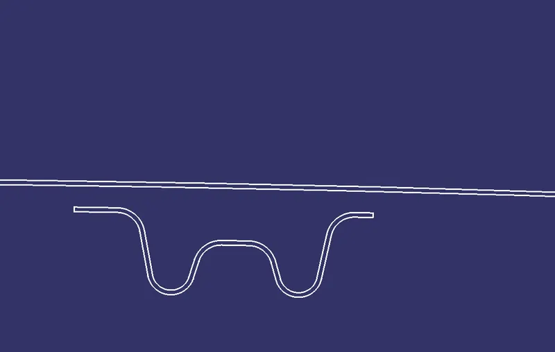
- The bow roofs are given to improve the torsional stiffness and load bearing capacity of the roof structure. The number of bow roof present is depends on the overall size of the roof.
There is given master section for referenence:
- Bow Roof-1
- Bow Roof-2
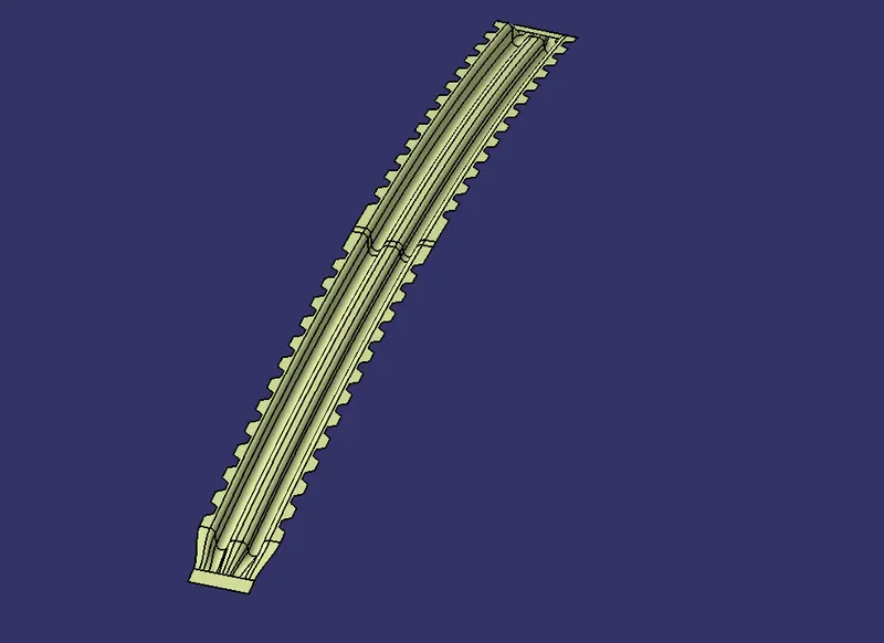
Step-5
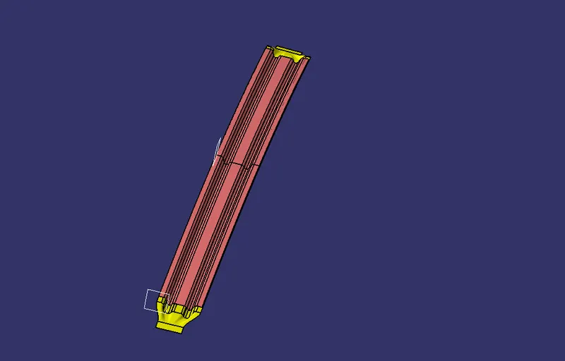
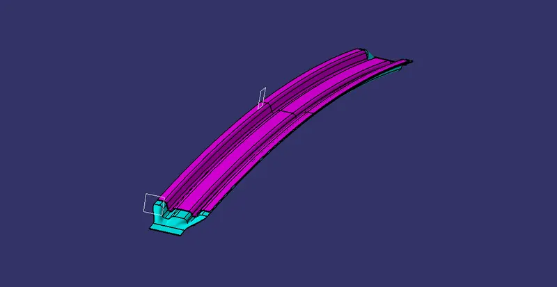
Design of Center Roof Reinforcement
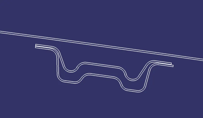
- Center Roof Reinforcement is located at the centre of the roof . The cross section of this is more since it needs to provide more strength to the roof. Here both are ends are joined together using mastic sealants.
Design Accordingly to the given Mastersection as Shown below:
Step-6
Design of Rear Roof Rail
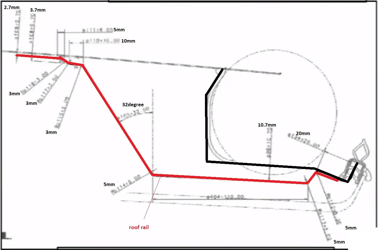
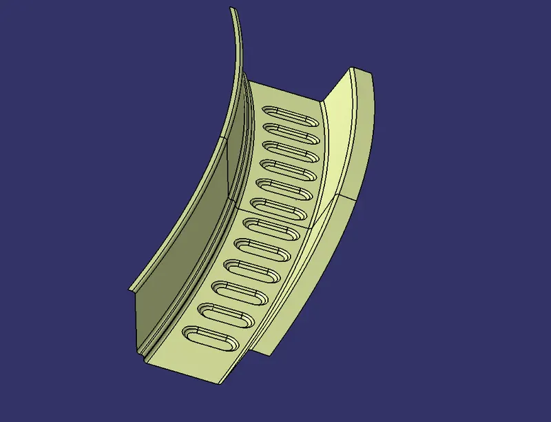
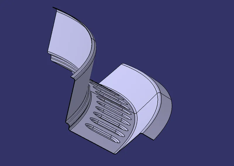
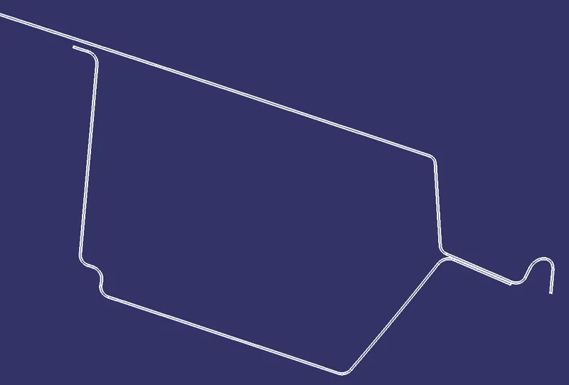
- Rear roof rail is the one which joins the back door and the body side outer.
Given master section for the rear roof rail for refrence purpose:
CALCULATIONS
Heat Distrotion Criteria
This study is used to find out and predict the heat distortion temperature at where the material starts to soften when exposed to a fixed load. So in order to avoid bending or damage of the roof based on this calculation we will decide the position on the roof bows on the roof.
Formula-:
W = [1.73 x 10^(-3) x L] + [1.85 x 10^(-8) x (R^2)/t] + [ 1.10x10^(-3) x l] - 2.68
Judgement Condition : OK< 2.7> 3.1
Where,
L = Roof Length in X-Direction[mm](Roof dimension in 0-Y)
R = Roof curvature
R = 2(Rx*Ry)/(Rx+Ry)
Rx = X curvature
Ry = Y curvature
t = Roof plate thickness [mm]
l = Bow Roof Span [mm]
Result:

Snow Load Creiteria
We predict the snow load in this of the roof bows and then place and change the design of the load accordingly to satisfy the condition.
Formula-
Qr =[Iy x t2] / [α x s x [(Rx + Ry)/2]2 x 10-8]
Note: The Qr value given over here is correct. There was a typo error in the formula given in the video.
Where
α = My x Lx2 x 10-12 , My = Y(Ly-Y)
Judgement condition = Qr ≥ 3.1
250 ≤ s ≤ 380
t = Roof plate thickness [mm]
Ly = Distance between the front and rear roof Rails on the Vehicle along with 0Y[mm]
Length of Roof panel with the center point between Roof rail Front /Rear as the reference point of the front and the rear.
Lx= Distance between the Left and Right end of the roof on the Roof BOW [mm]
Width of the roof panel exposed on the surface.
Y = Distance front Front Roof Rail to Roof BOW[mm]
s= Distance for which Roof BOW bears divided load [mm]
s = L1/2 + L2/2
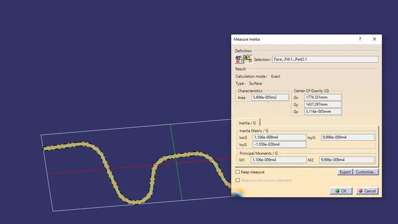
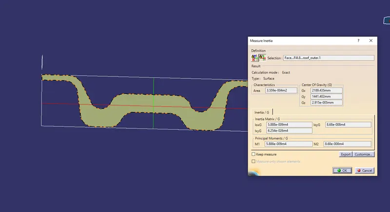
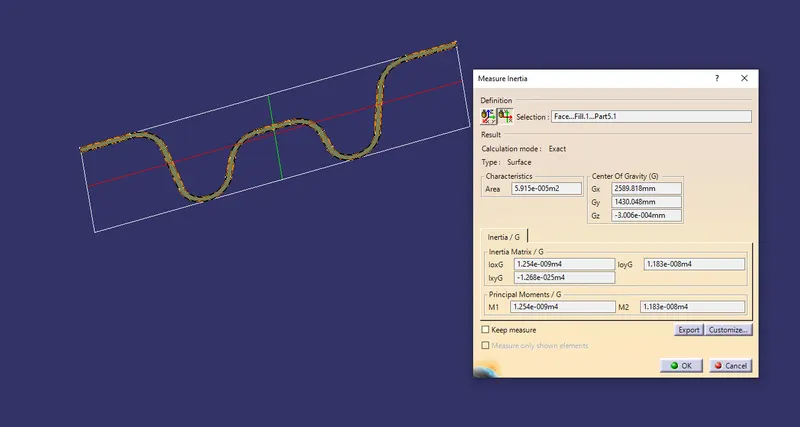
Iy = Geometrical moment of inertia of Roof BOW (Y cross-section )[mm4]
Rx = Lateral direction curvature radius of roof panel Y cross-section on Roof BOW [mm]
Roof panel curvature Radius of the Length Lx in Front view
Ry = Longitudinal Direction curvature radius of the Roof panel X cross-section on Roof BOW [mm]
Moment of inertia-
Bow Roof-1
Center Roof Reinforcement
Bow Roof-2
Result-

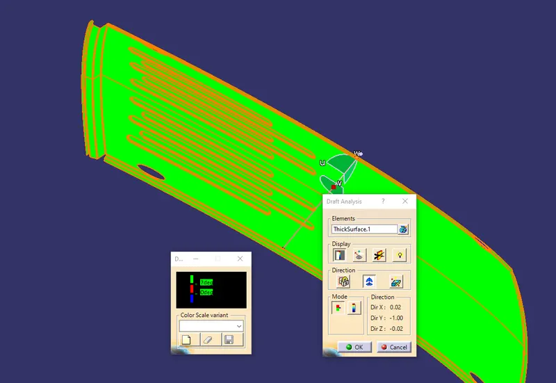
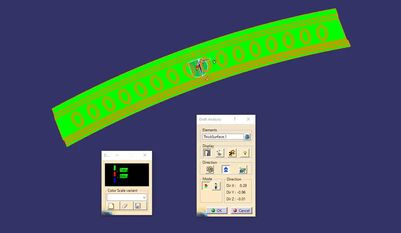
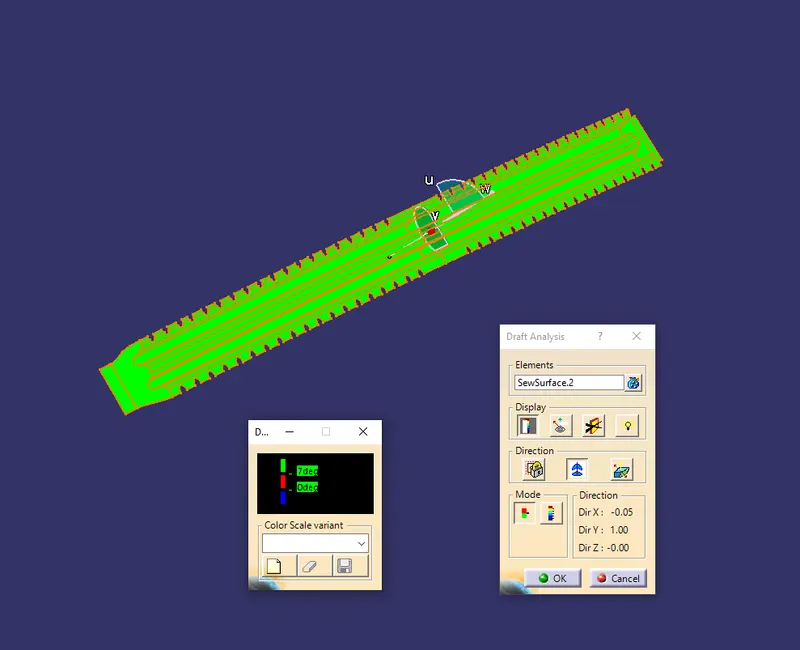
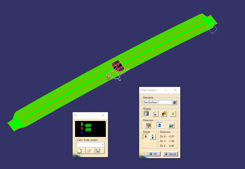
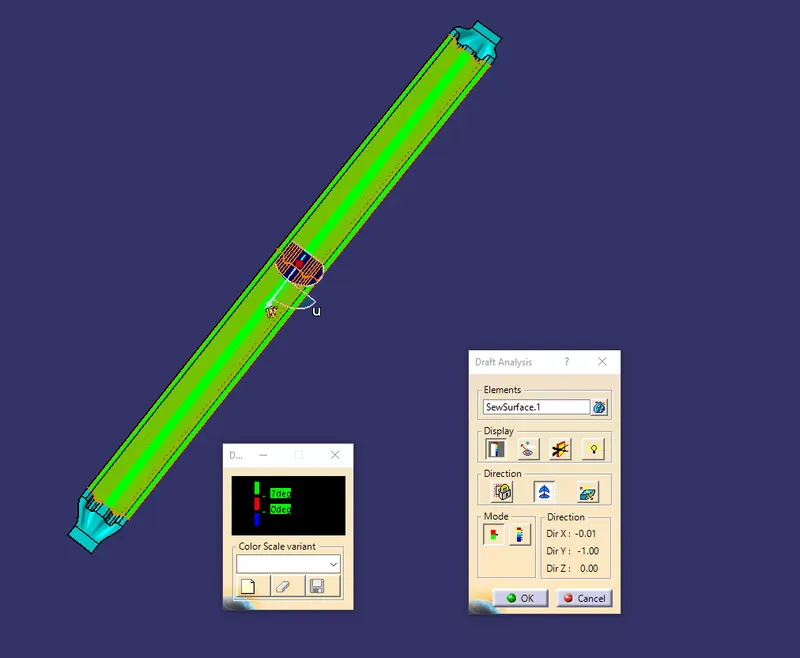
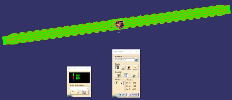
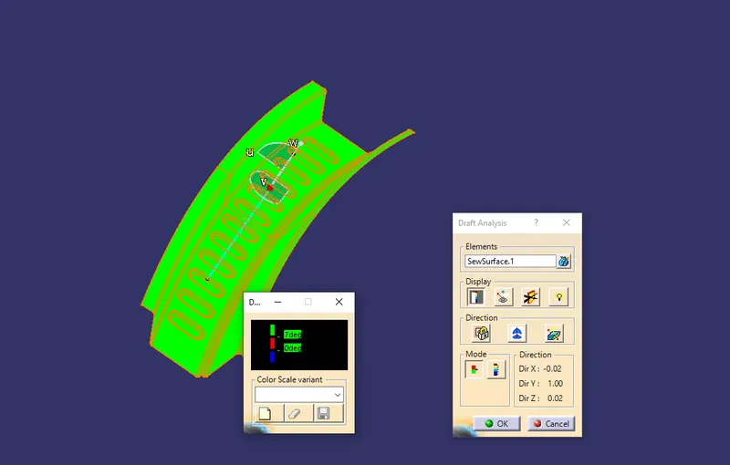
Draft Analysis
Before we give the part for manufacturing we have to some analysis ourself to check all the constraints and to check if we have any negative draft on a part .
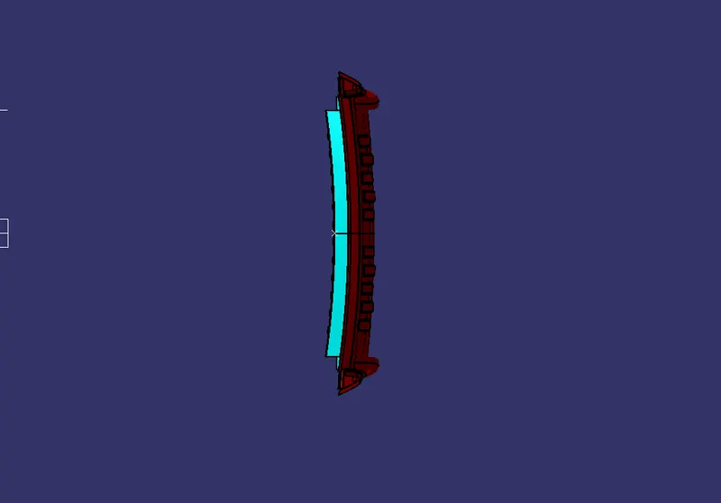
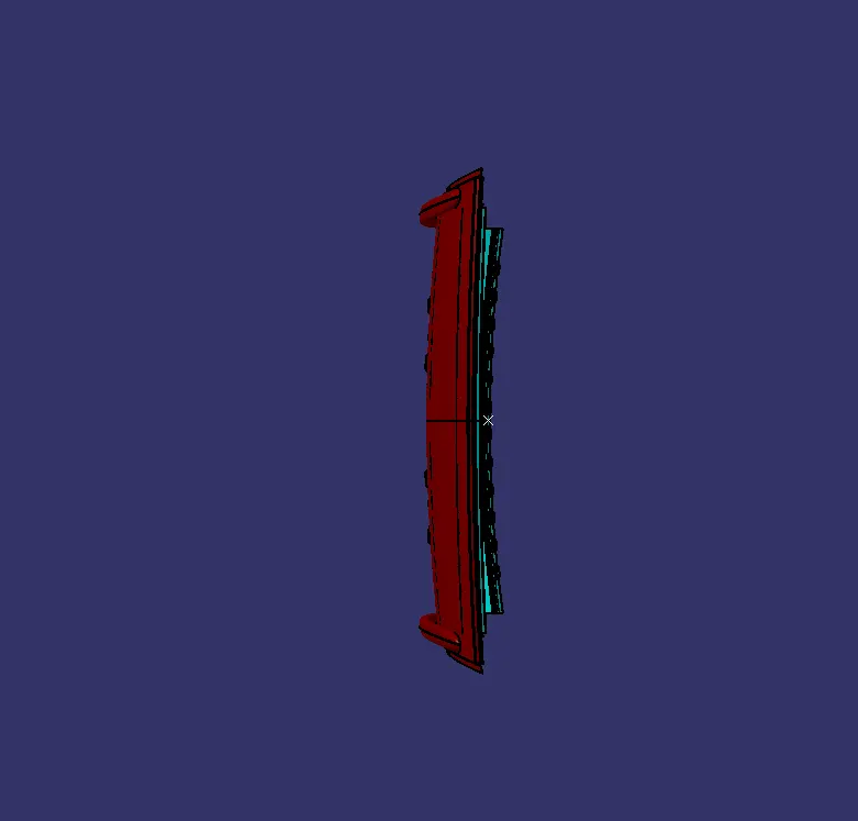
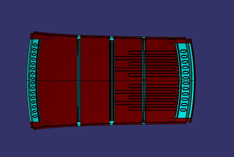
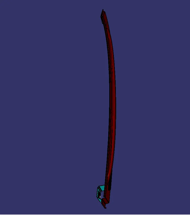
VIEWS
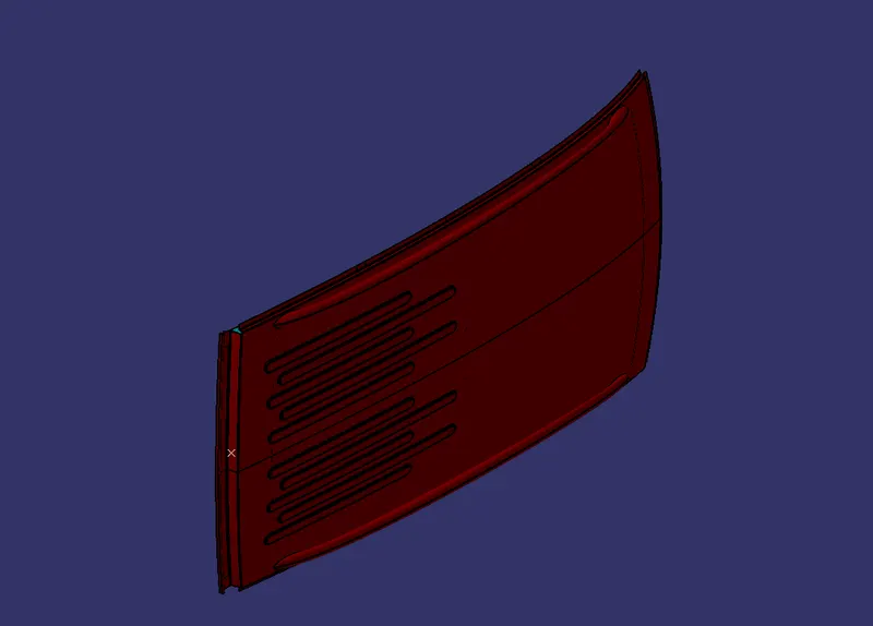
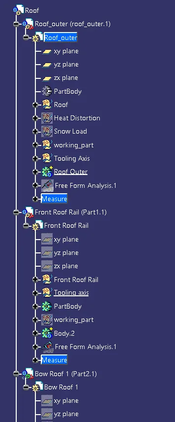
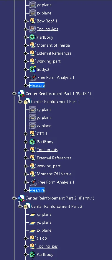
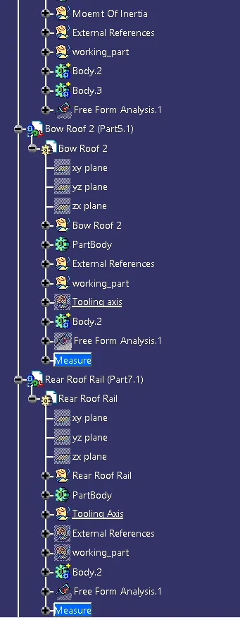
TREE STRUCTURE