Week 11- Assembly Workbench
AIM
TO create 2 assemblies according to the provided 2D diagrams of the components . First create the individual part files and then create a complete assembly of those part files in the assembly workbench. After creating the assembly make use of the drafting tools to create a 2D drawing.
OBJECTIVE
This assignment is for to get an hand's on experience on assembly environment and integration of assembly with the subsciquent workbenches. It is always necessary to create a project with flexiblity to changes, so that the upcoming modern advancement's can be easily adopted with respect to the current senariyo. This assignement act's as a core referance of working module in the CAD based industries.
INTRODUCTION
. Quick Return Mechanism:
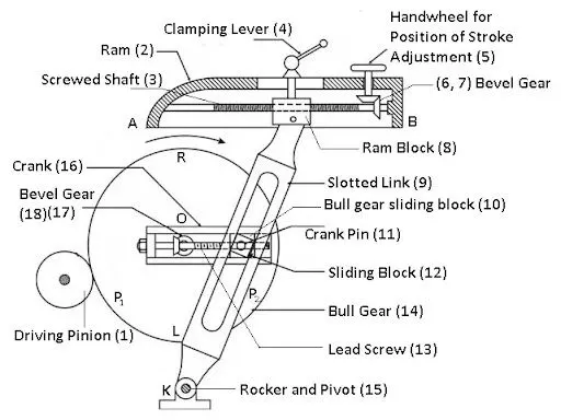
A quick return motion mechanism is used in the shaper and slotter machine in which the circular motion is converted into reciprocating motion so that the slider moves forward and backwards. In the forward direction, the cutting process occurs while in return there is no such cutting. The bellow shown Crank and Slotted Leaver Mechanism is an example of Quick Return Mechanism.
. CV Joint:
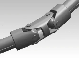
Constant-velocity joints (also known as homokinetic or CV joints) allow a drive shaft to transmit power through a variable angle, at constant rotational speed, without an appreciable increase in friction or play. They are mainly used in front wheel drive vehicles. Modern rear wheel drive cars with independent rear suspension typically use CV joints at the ends of the rear axle halfshafts and increasingly use them on the drive shaft. The below image is Thompson constant velocity joint (TCVJ) which is one type of CV joint also known as Thompson Coupling.
. Part Modeling:
The part modeling is done based on the drawing which is given as a input, as per the modeling requirement the parts are constrained together to transmit motion, so that the parts could be designed in such a way as it constrains with the subsciquent parts easily. Inorder to view the results easily and to adopt changes the main results are published. So that instead of making changes in each and every part, the parts which are engaged together with the subsciquent parts are changed automatically. Each and every company uses specific templets to enter its parts information as a customizable tool, which helps the industrial persons to proceed there work without errors.
QUICK RETURN MECHANISM
Procedure:
Step-1
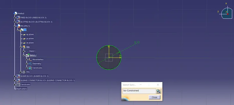
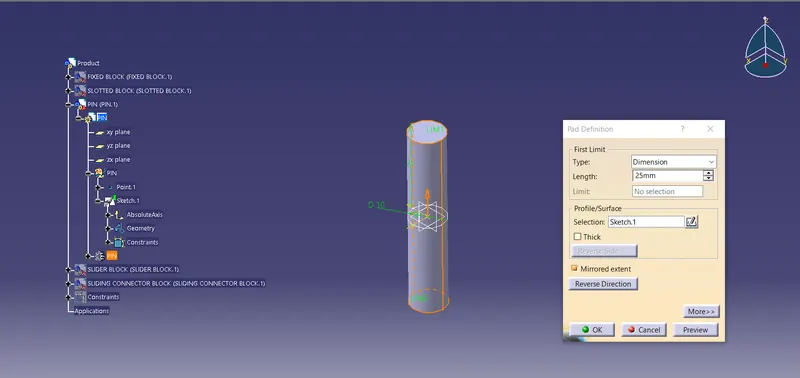
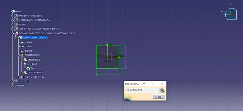
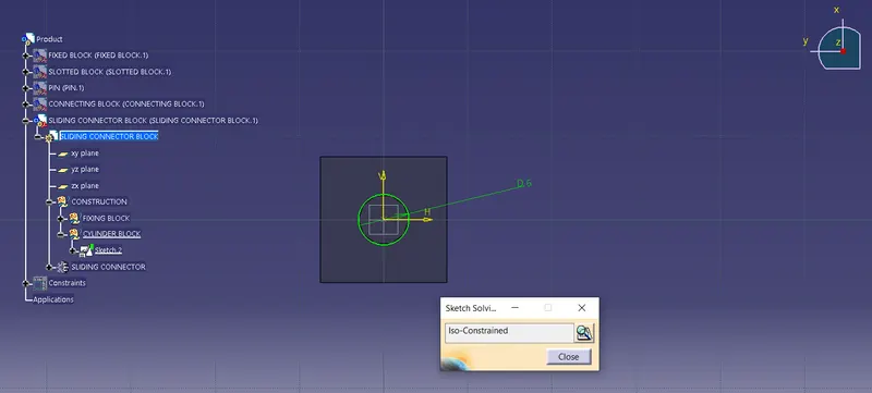
Create sketchs for all the parts of the Quick Return Mechanism which is given in the 2D diagrams in Part Design workbench.
Step-2
Assembly Design:
- First insert all the existing parts of the Quick retturn mechanism into Assembly Design as shown below.
- Then arrangle the parts properly using manipulation option from the toolbar according the 2D diagram so that can use constrains properly.
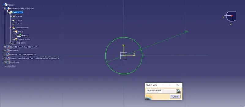
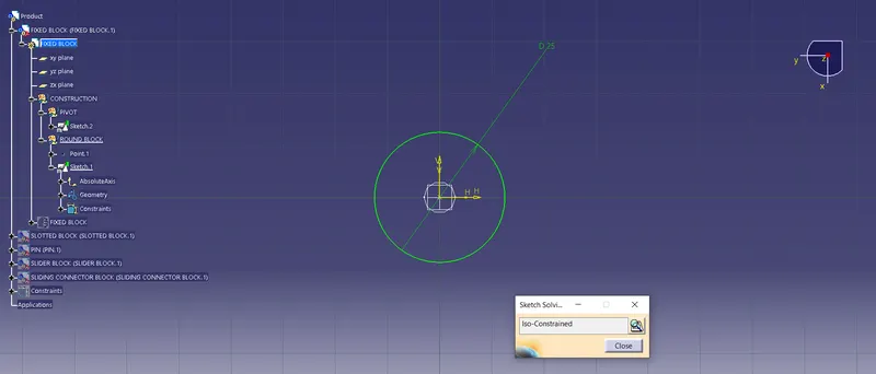
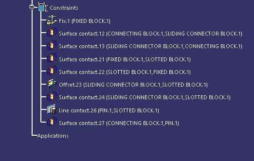
- Next ias to constrain the Pivot part using Fixed constrain from the toolbar as shown below.
- Using the Surface contact constrain the Slotted Body .
- Then after constrain the Slider body using both Surface contact and Offset(As per required value) constrain.
- Now constrain both Connecting body and the Slider body with the Surface Contact.
- To make sure that it is properly assembled use Manipulation tool with respect to the constrain as shown below.
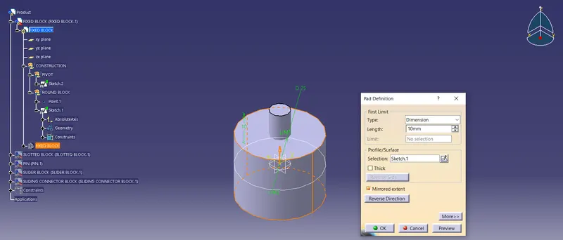
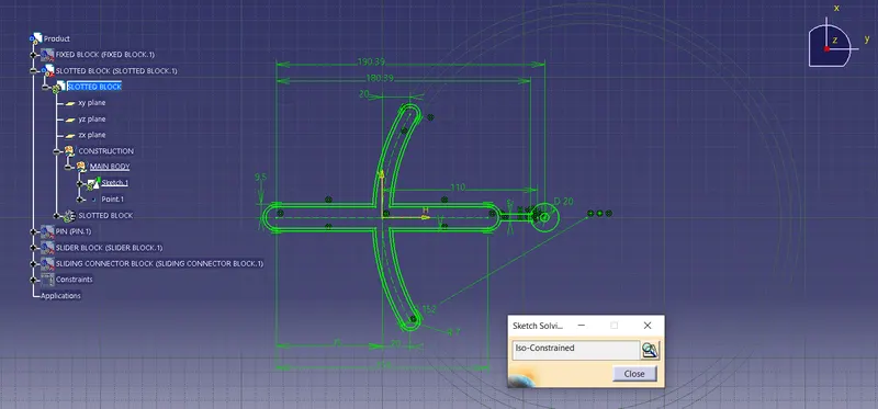
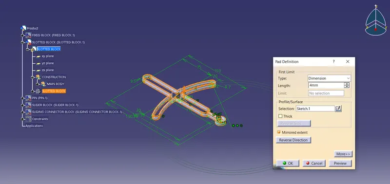
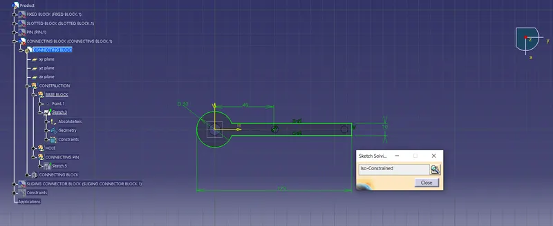
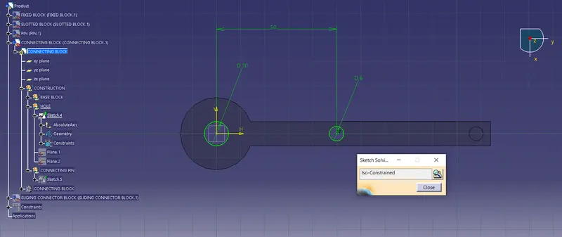
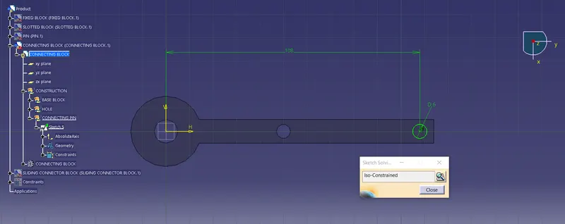
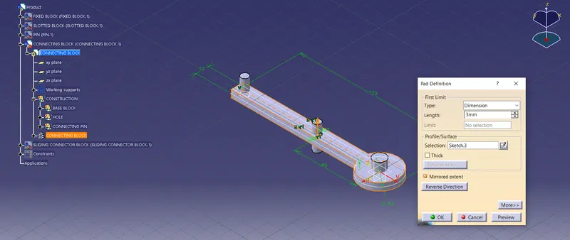
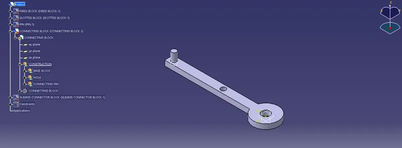
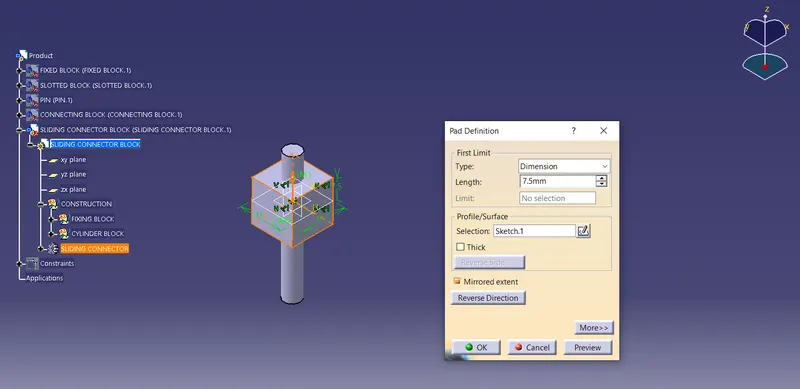
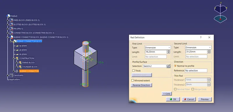
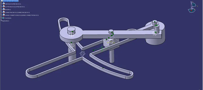
[Quick Rturn Mechanism]
VIEWS (ISOMETRIC, TOP, FRONT, SIDE)
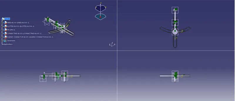
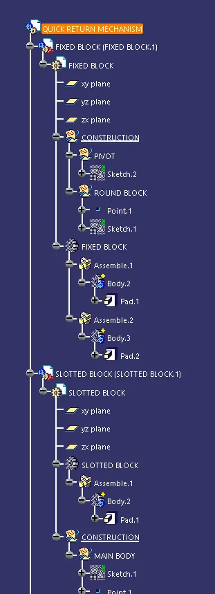
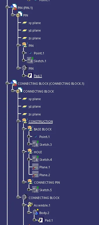
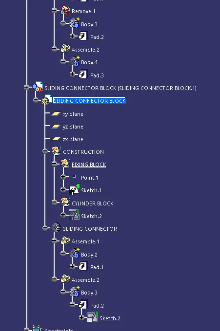
TREE STRUCTURE
CV JOINT
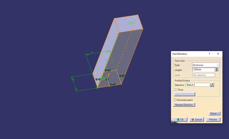
Step-1
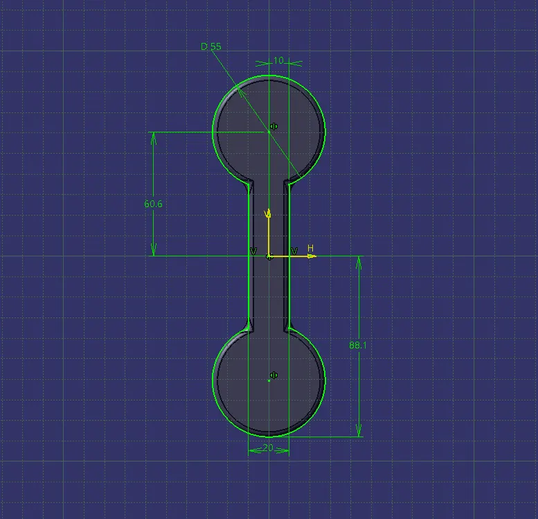
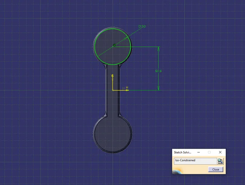
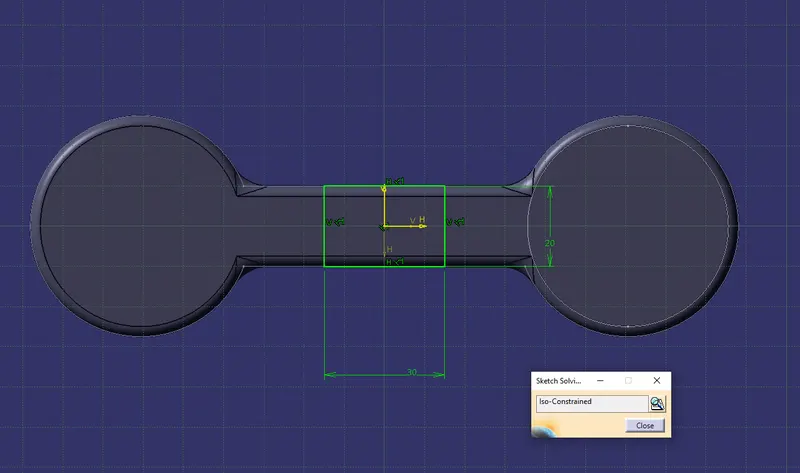
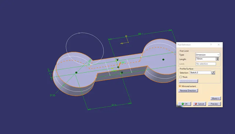
Create sketchs for all the parts of the Quick Return Mechanism which is given in the 2D diagrams in Part Design workbench.
Step-2
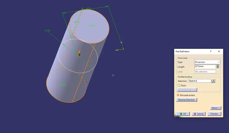
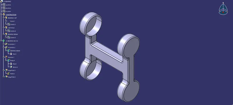
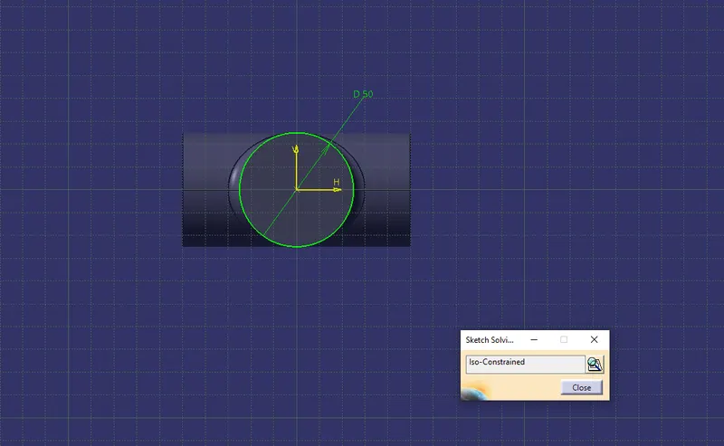
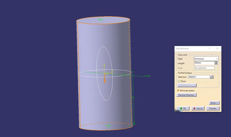
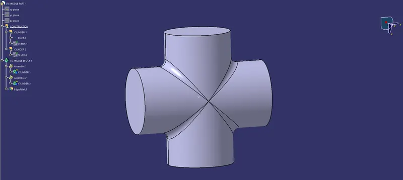
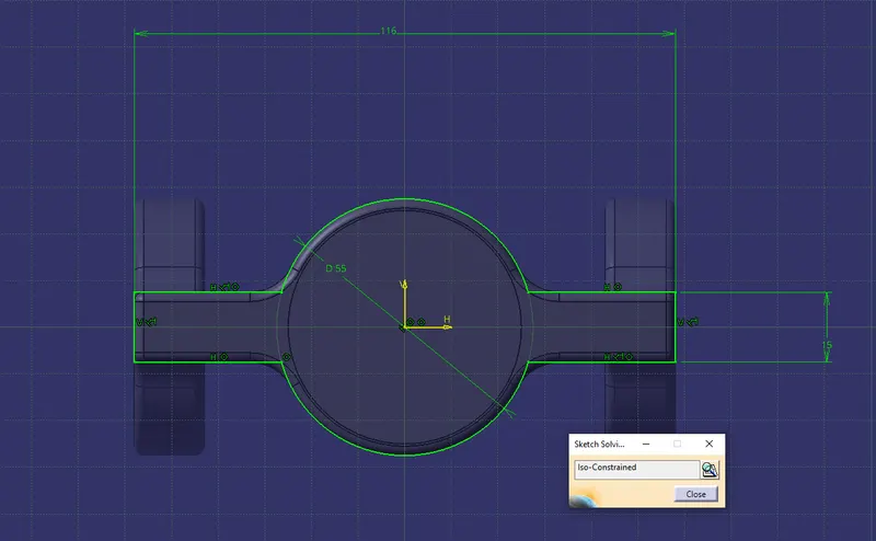
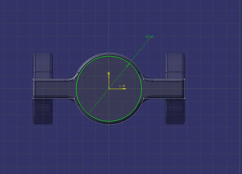
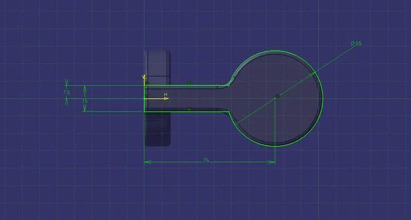
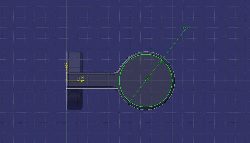
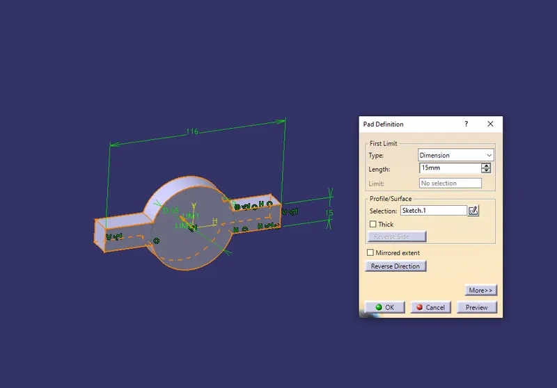
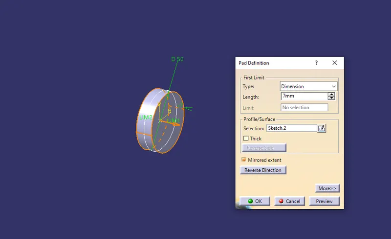
- Sketch different parts of CV joint in part design as per given diagram.
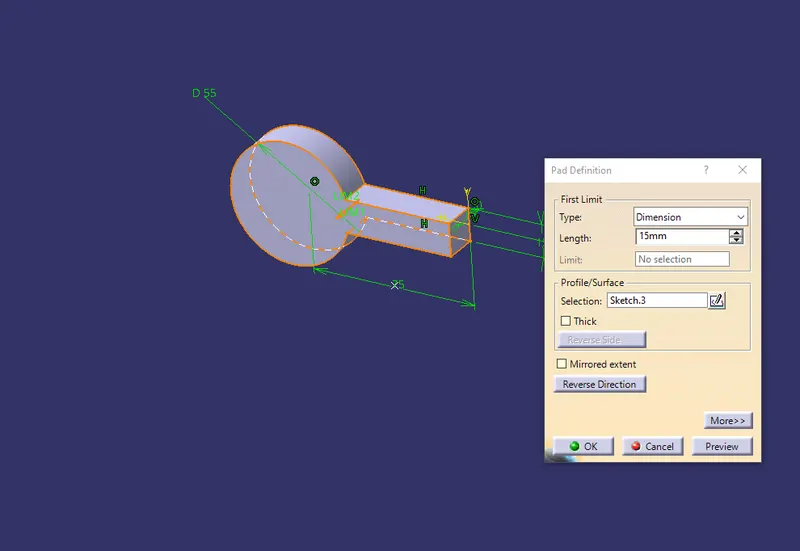
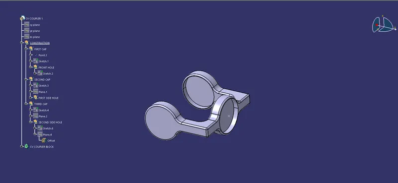
Step-3
Assembly Design:
- Same as before Existing Parts into the Assembly Design.
- Then using Fix constrain fix the CV Bearing.
- Now place the Middle Parts inside the CV Bearing using Coincidence constrain.
- Next wiil be use Offset Constrain to the Middle Parts so it can be fitted properly inside the Bearing.(Offset value as per user requirement)
- For the Couplers use both Coincidence and Surface constrain with the Middle parts.
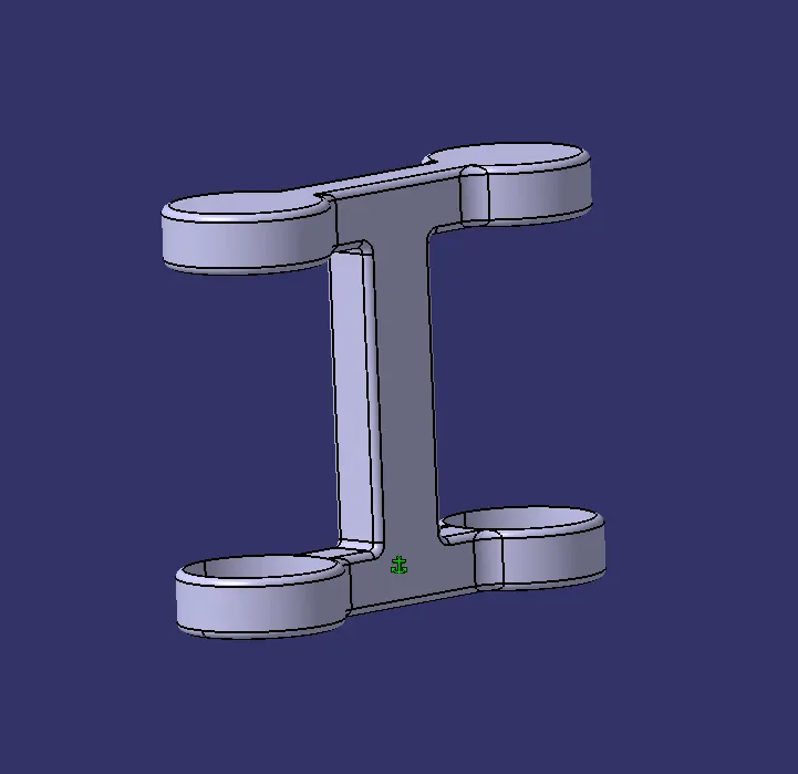
[Fix Constrain On Bearing]
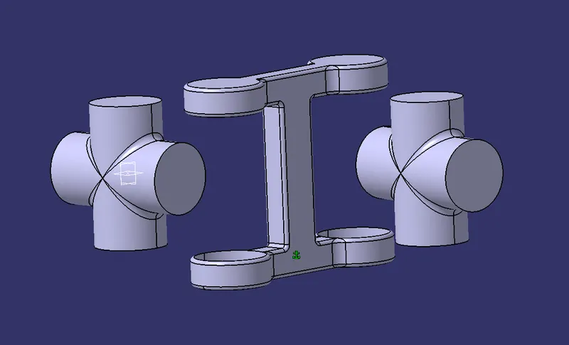
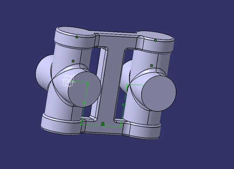
[Offset & Coincidence on Middle Parts with Bearing]
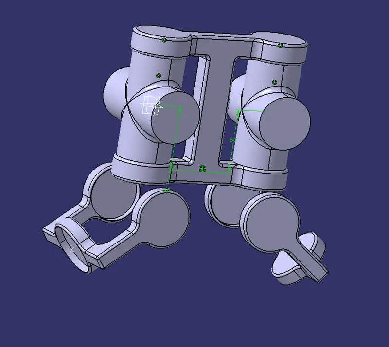
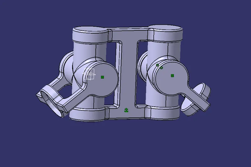
[Coincidence & Surface Contact Constrain on Couplers with The Middle Parts]
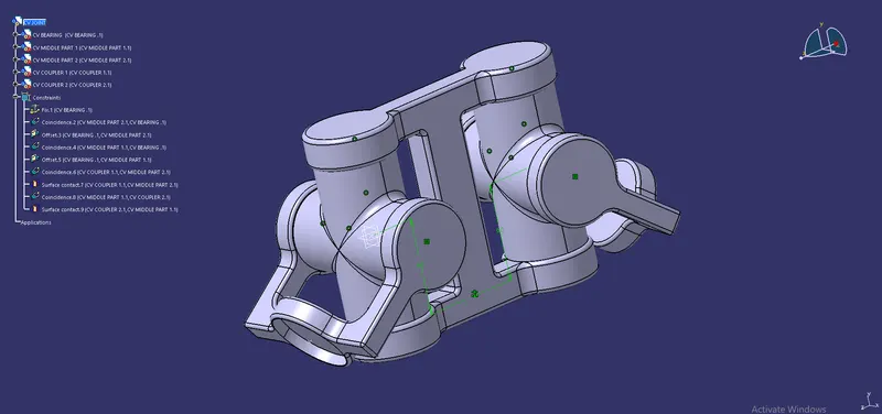
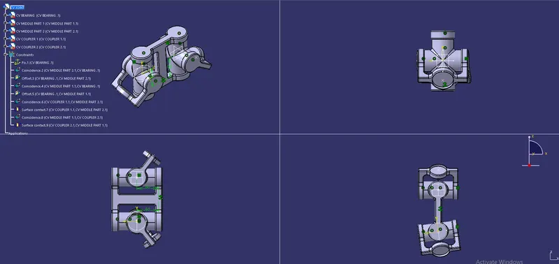
[Assembly CV Joint]
TREE STRUCTURE
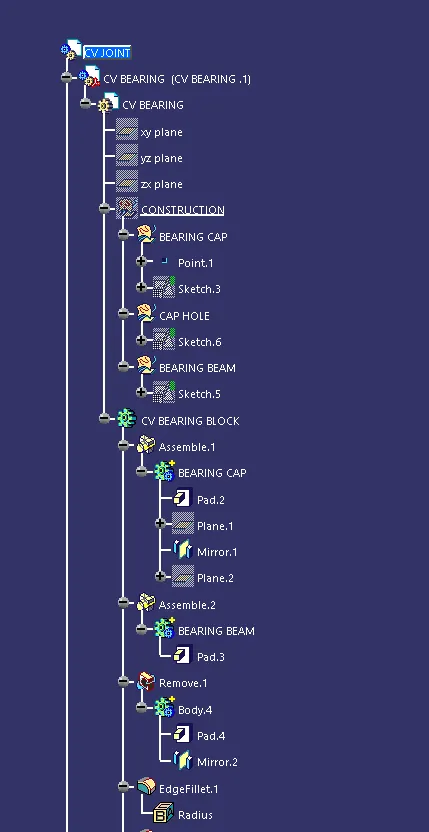
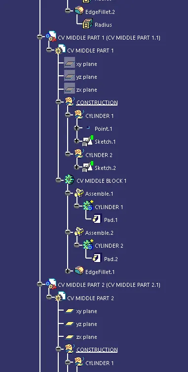
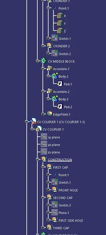
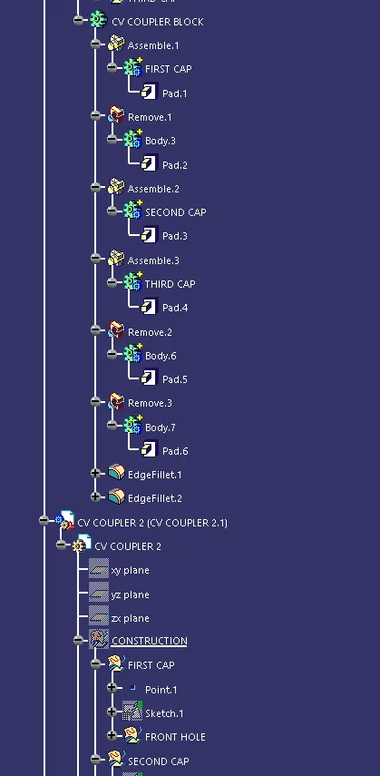
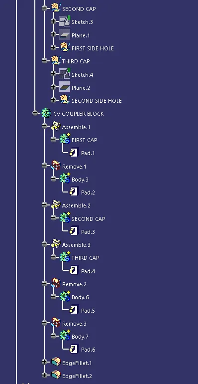
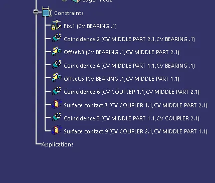
VIEWS (ISOMETRIC, FRONT, SIDE, TOP)
CONCLUSION
created 2 assemblies according to the content covered in the course videos. You will be provided with 2D diagrams of the components and you will have to first create the individual part files and then create a complete assembly of those part files in the assembly workbench. After creating the assembly make use of the drafting tools to create a 2D drawing similar to the one given in the assignment folder.
{NOTE- Drafts are in the file}