Door Arm Rest Week 8 Challenge
DOOR ARM REST
AIM
Creating a door arm rest with thickness of 2.5 mm and performing draft analysis ont it.
OBJECTIVE
- Analyzing tooling direction and creating tolling axis.
- Creating the B and C surface.
- Performing draft analysis on both A surface and final door arm rest and draft analysis must ahiw posistive value and color.
- Creating solid body out of it.
PROCEDURE
Step-1:
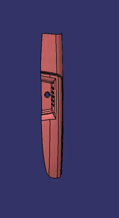
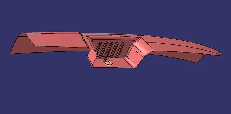
First step is to insert the class A surface into CATIA V5 and then analyze tooling for the door arm rest.
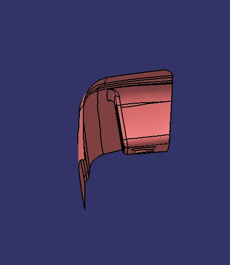
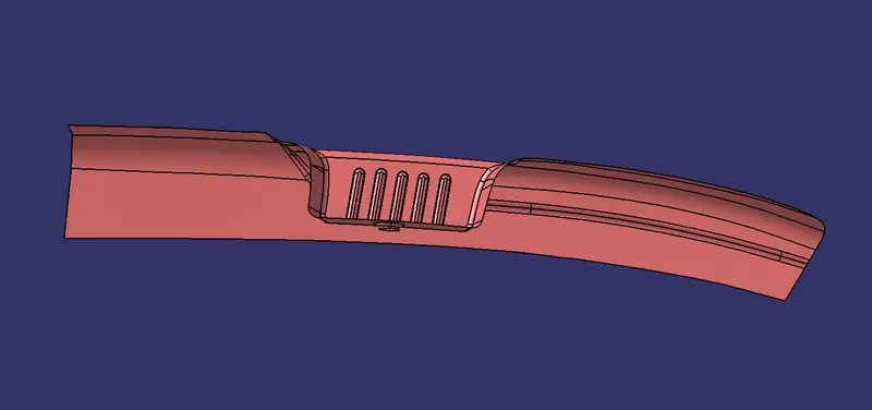
Step-2:
CREATING TOOLING AXIS
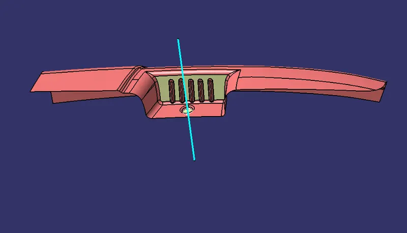
After analyzing tooling direction of class A surface there is a need of two tooling axis for this class A surface because there is need side core here. The tooling axis are Main Tooling Axis and Side core tooling axis.
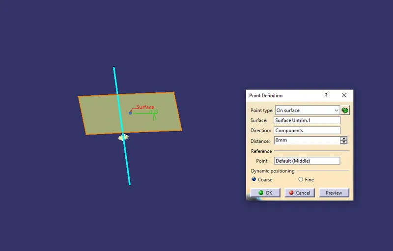
After this we have to creat reference point for tooling axis.
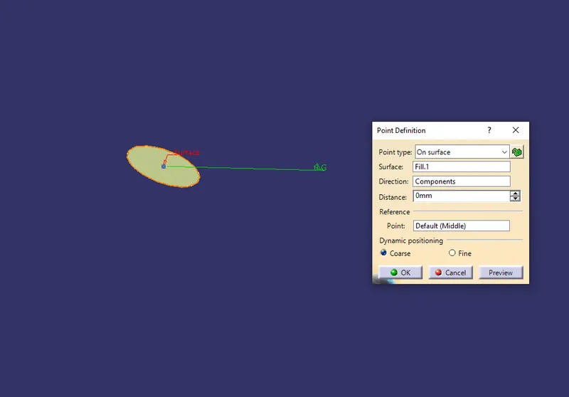
Now their is two possible tooling axis for this Class A surface so we have to create two points.
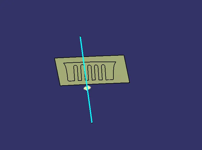
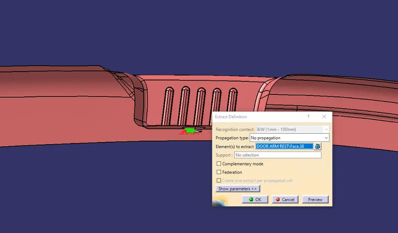
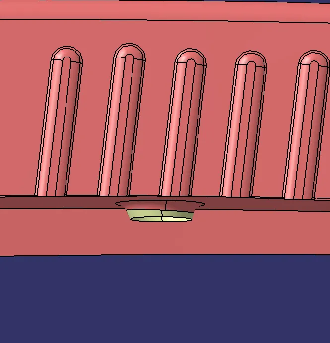
- For first point extract the hole and use Fill command and theen using Point command create cente point on that surface as shown below.
- Second point is created by extracting the side surface with features from class A surface and utrim it. Then use the point command to create the point as shown below.
- one is a main tooling axis which clearing in Z direction which will be created using compass direction.
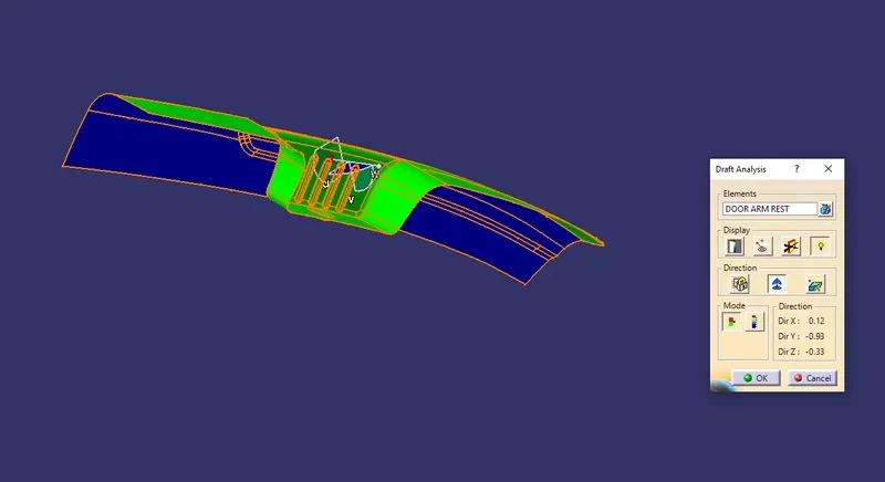
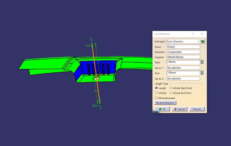
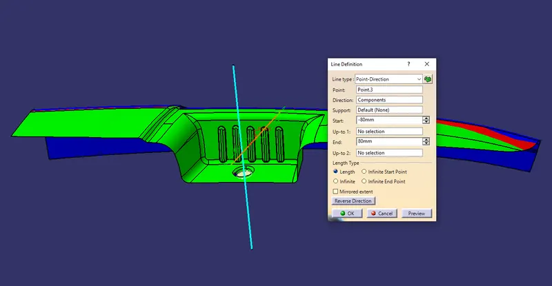
- For the side walls with styling features on class A surface there is need of side core tooling axis which will be created using compass direction in line command.
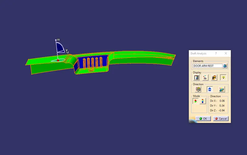
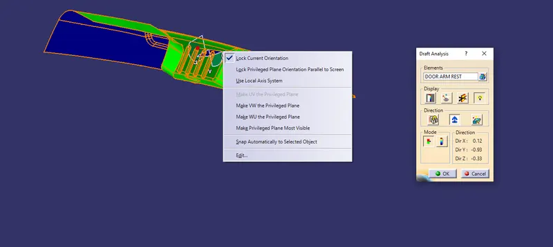
For creting tooling axis we are using compass direction method where we are directly using draft anallysis to create tooling axis by draging the compas on the class A surface and try to clear as many surface as possible on the main tooling axis direction with positive draft and rest in side core tooling direction.
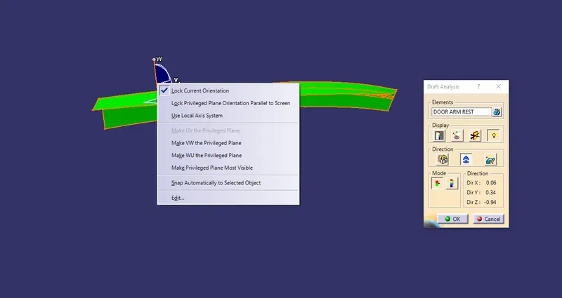
Then lock compass using right click on the position where it clearing most the surfaces in both main and side tooling axis direction. Now using both the points we have created as reference in the Line Command where give the direction the as compass direction to create two lines which will be our tooling axis for Main and Side cores as shown below.

Step-3
Draft Analysis
For Performing draft analysis on Class A surface
Go to MenuBar > Insert > Analysis > Feature Draft Analysis. Then performe draft analyiss for each tooling axis . To performe draft analysis click the red dot appering on the Class A surface and Then go to display tab on draft analysis click color scale where it shows different color which represent diffrent draft angle. The minimum draft angle is 3 degree. Here Red is Zero , Green is Above zero degree and Blue is below zero. So try to keep the draft angle in positive.
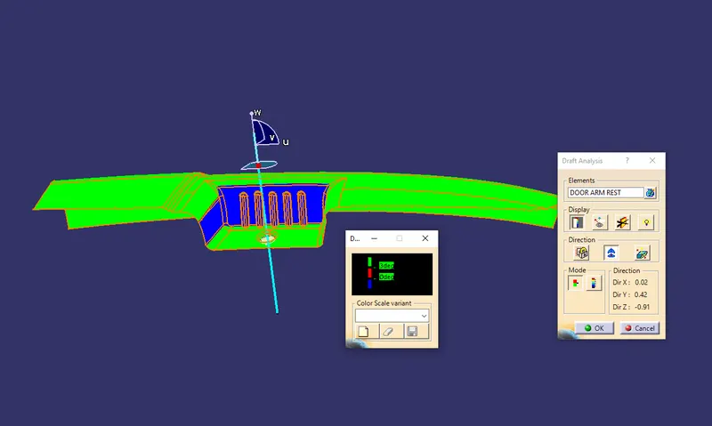
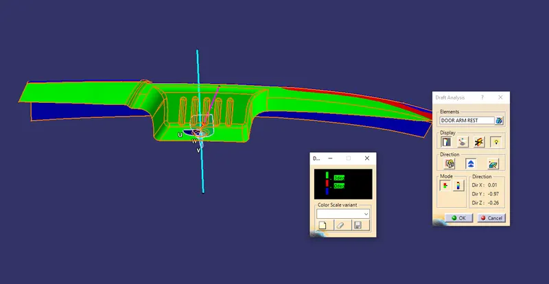
Step-3
CREATING B SURFACE
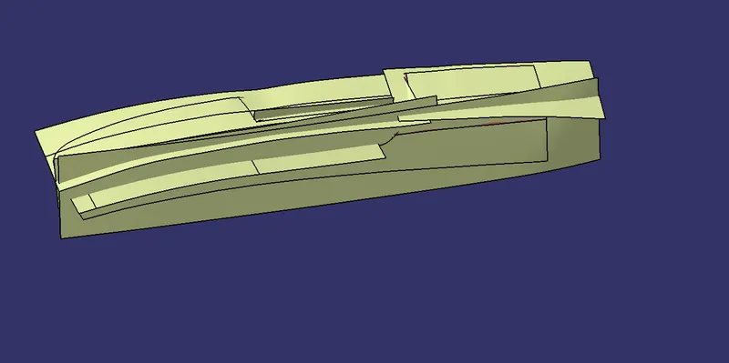
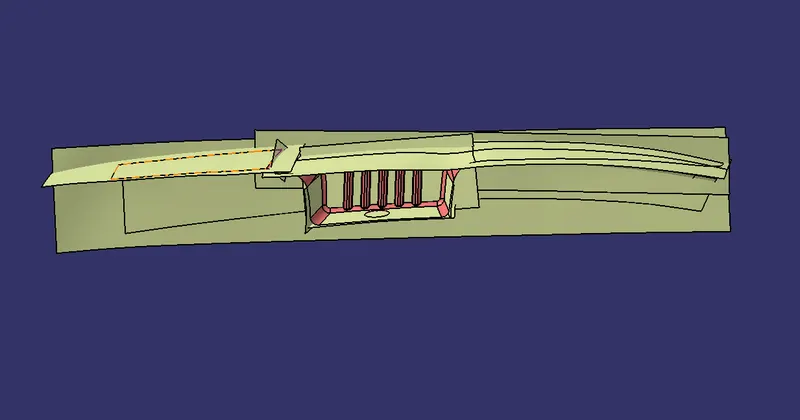
- First extract all the necessary flat surfaces from the class A surface.
- Then untrim these surfaces to get intersection for surfaces so that replica can be created.
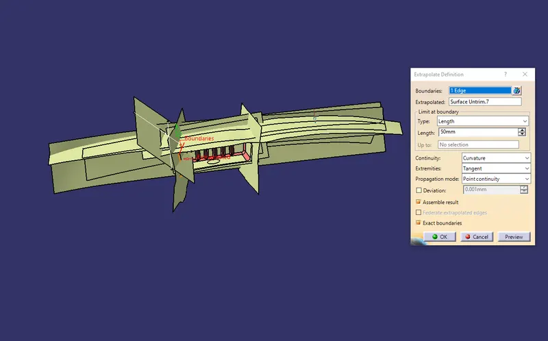
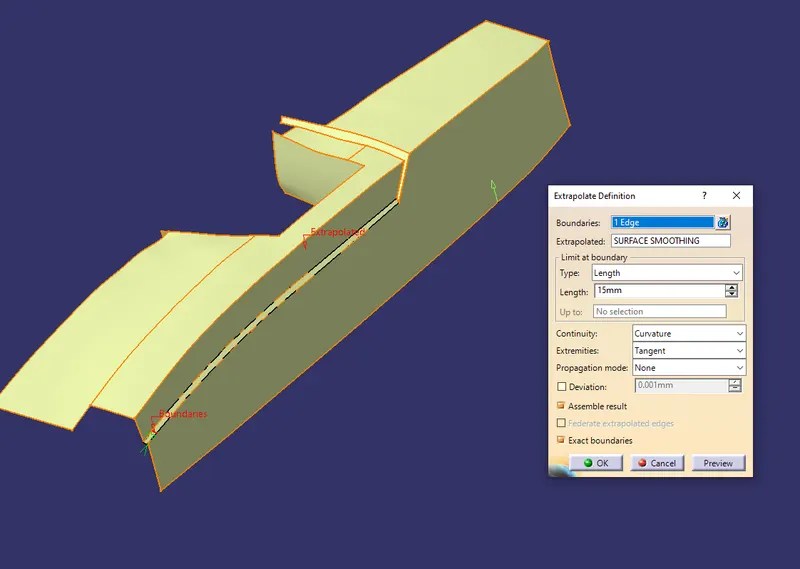
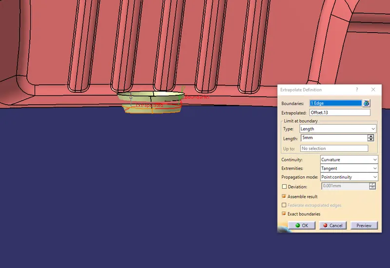
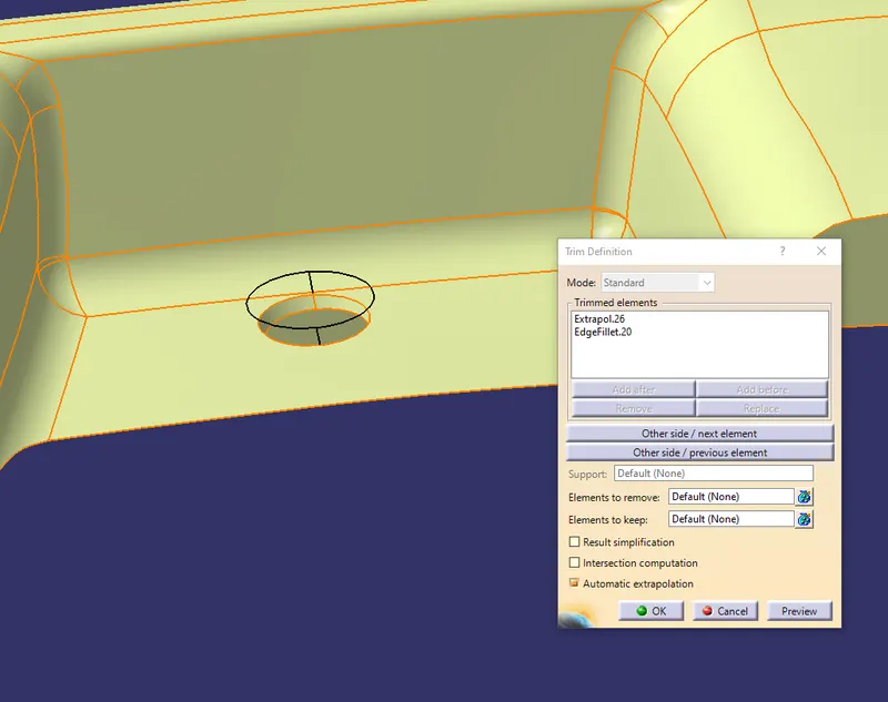
- If the surfaces are not intersected, then extrapolate by point continuity propagation is used to make these surfaces have an intersection between them.
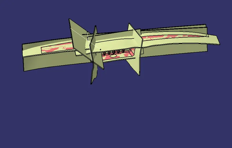
- Then offset all the extracted surface by thickness of 2.5 m as given to obtain B surface.
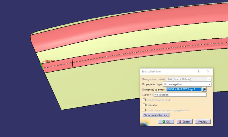
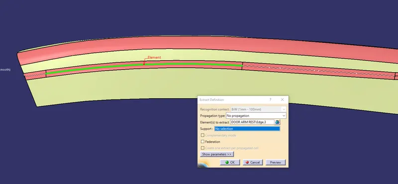
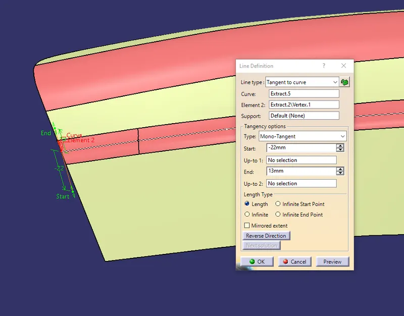
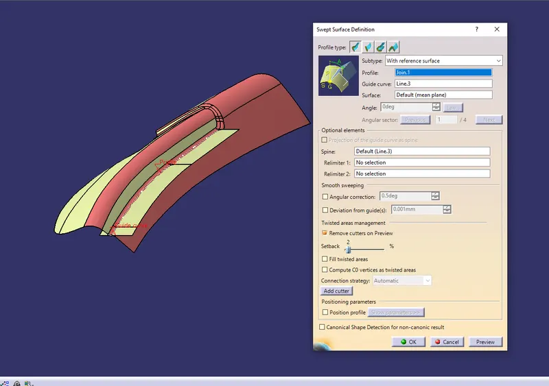
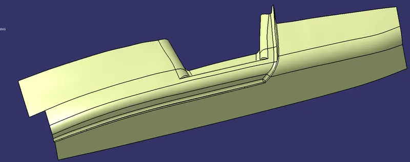
- One surface where you won't able extract the surface because of the fillet in that case extract the boundry of that surface and creat a guide line taking one boundry as tangent curve reference in Line command and Sweep it .
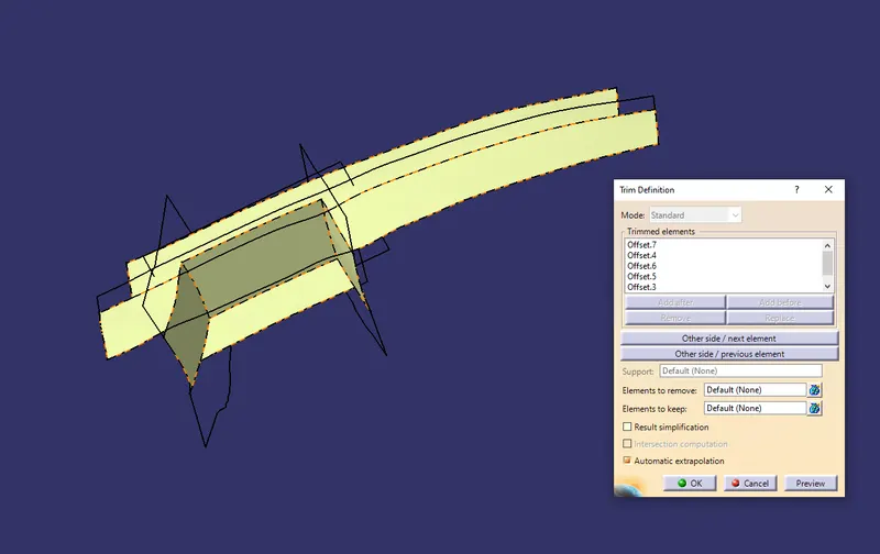
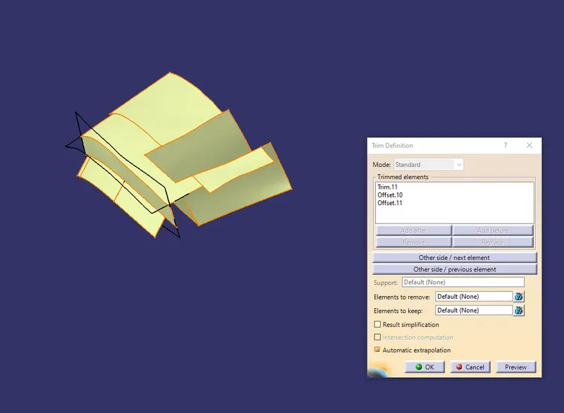
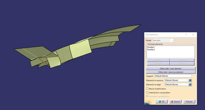
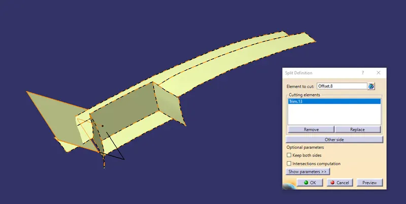
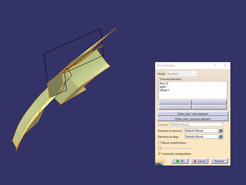
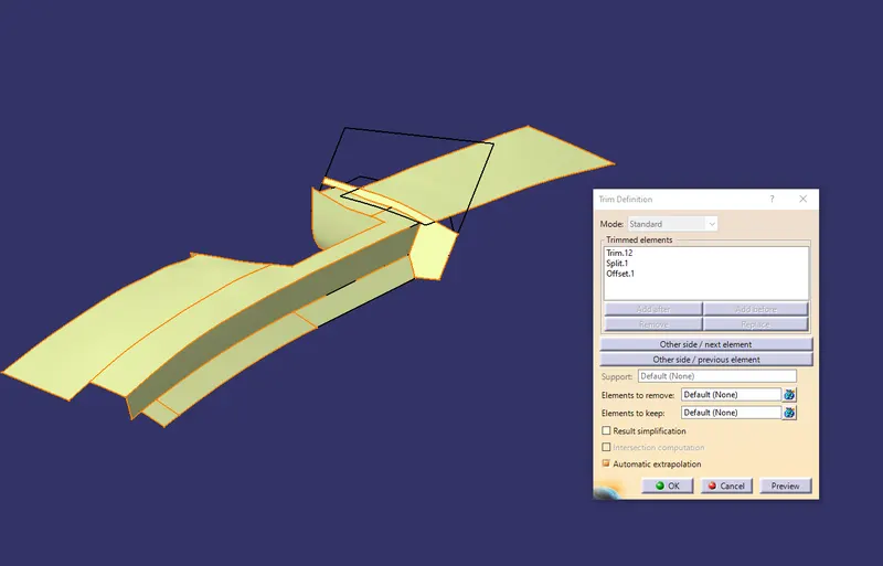
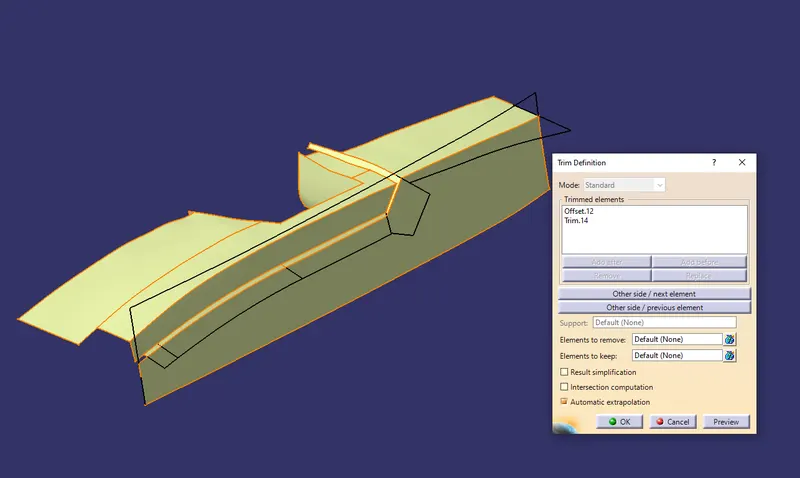
- Next surface trim is used to get the Class B surface.
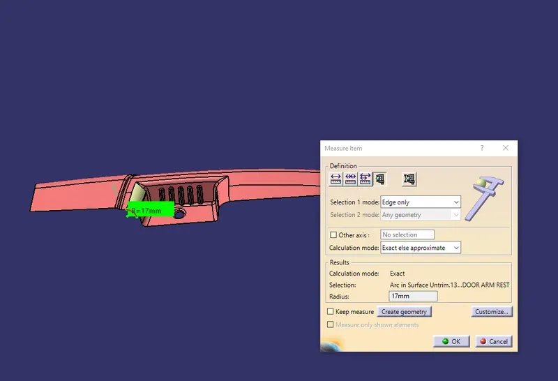
- Lastly measure the fillets from class A surface and give to the surface according to the formula
Fillet:
(If it is inward A surface then; Radius = A surface fillet radius - Thicknes of the component(2.5mm))
(If it is toward B surface ; Radius = A surface fillet radius + Thicknes of the component)
Extract-
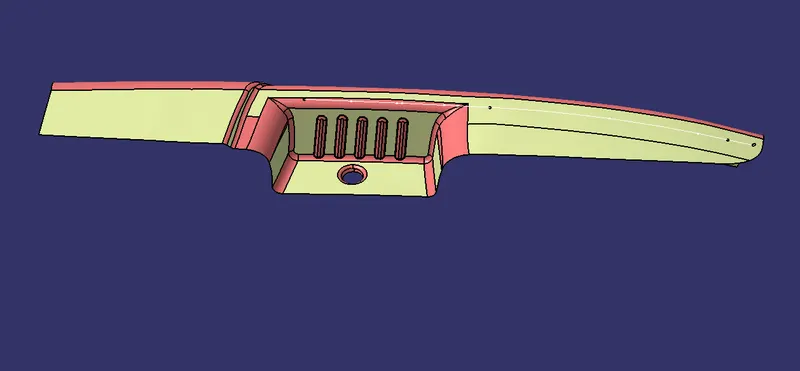
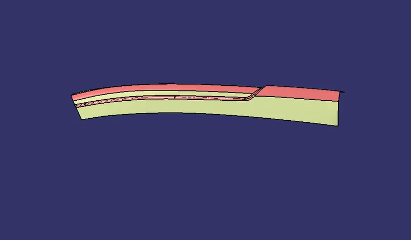
Surface Untrim-
Extrapol-
Offset-
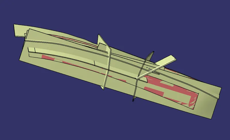
Surface Trim-
Fillet-
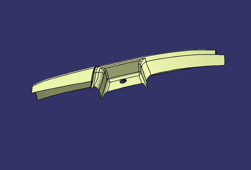
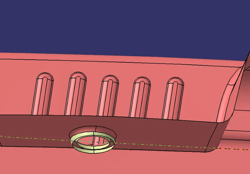
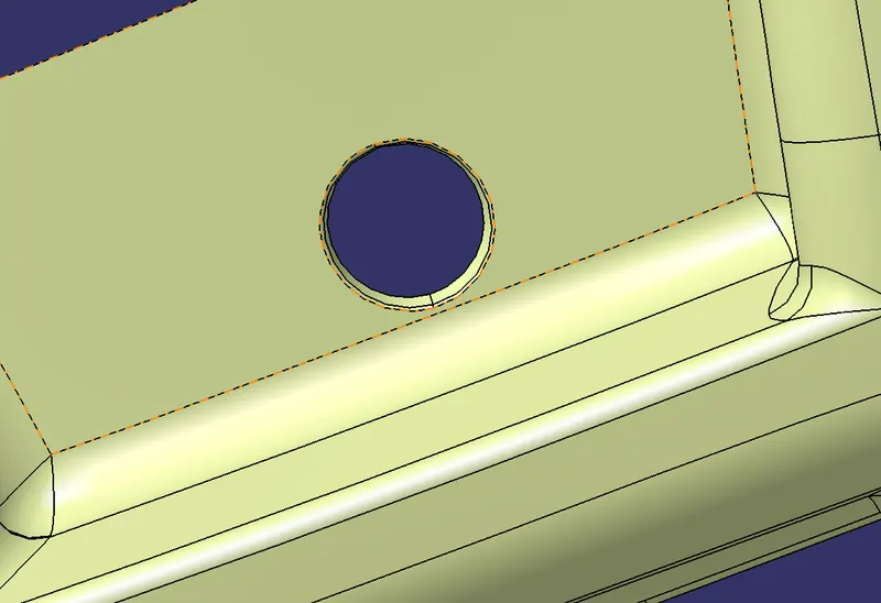
Hole-
Step-4
CREATING C SURFACE
.C class is where the thickness of the component lies. It is joining surface between A-surface and B-Surface.
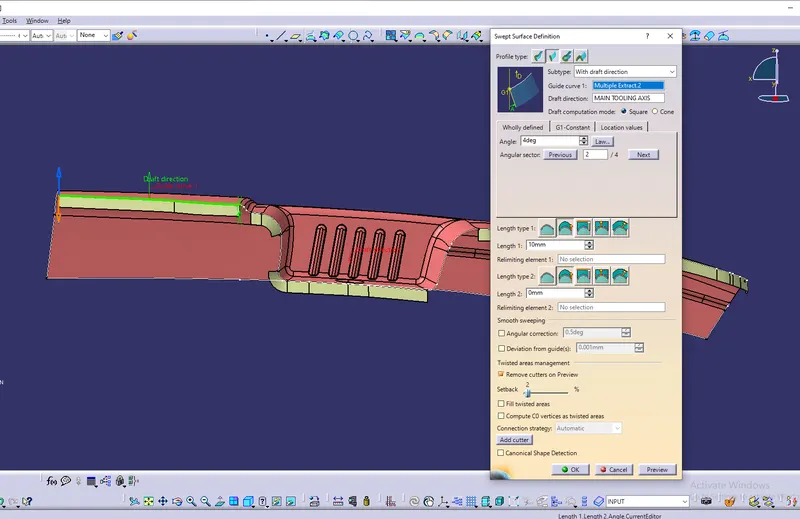
.For creating C surface we are using Sweep command most of the cases and for that the boundry lines are obtained from the A-class surface.
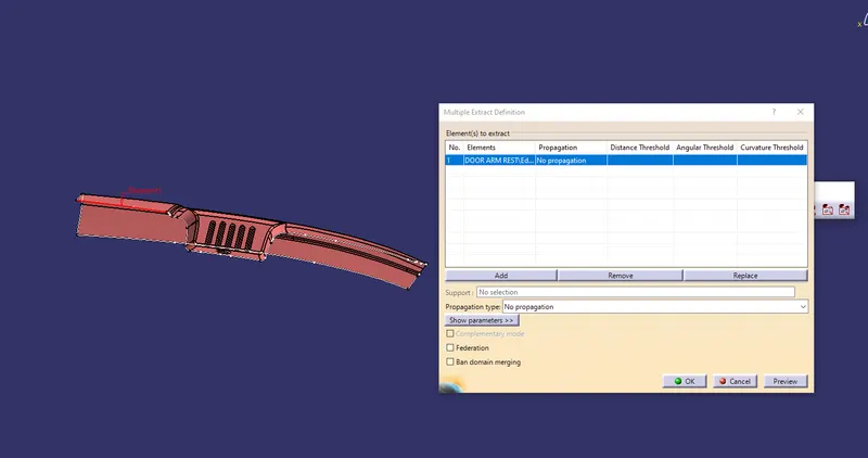
.All boundry lines are sweep with draft direction since all the surfaces must have a draft angle of minimum 3 Degree or more than that so that component eject easily from molding.Also the tool axis is used as the direction of the sweep.
.But some cases like complicated curves we use Multi-sections Surface command.
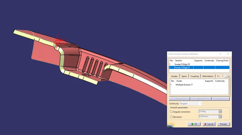
Trim-
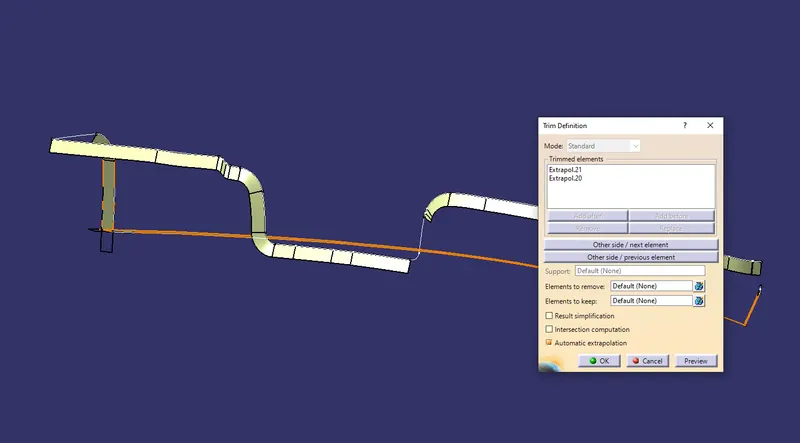
Join-
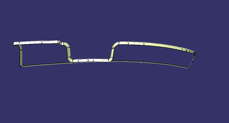
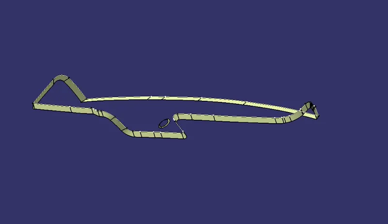
.Next, the Swept surfaces joined with the Class A surface to a complete A and C surface.(Note-Merging Distance kept at 0.003mm to avoid any gaps)
.Still if there is any one we acn do Extrapolate A surface by 0.5mm and trim with the C-surface.
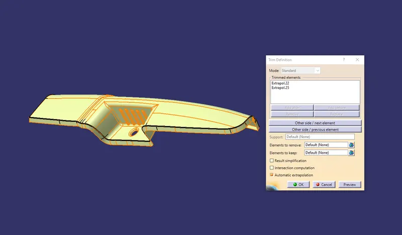
FINAL DOOR ARM REST SURFACE
Now, trim B surface with Joined A and C surface to get Final surface.
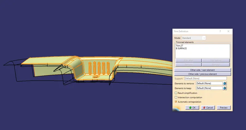
.Then make a solid body out of it as shown below.
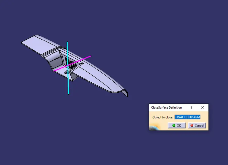
DRAFT ANALYSIS
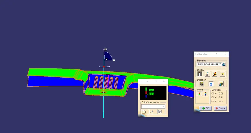
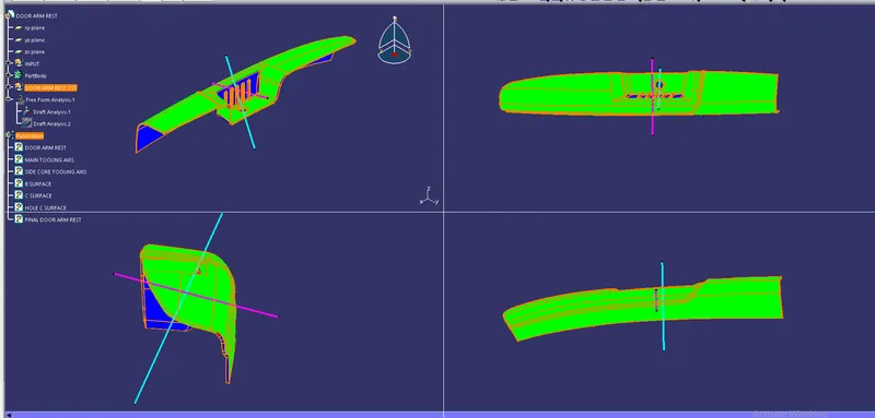
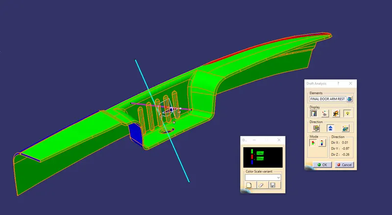
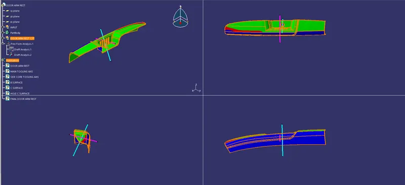
Next performe final draft analysis with both tooling directiom on the final surface for feasibility of the component. Where minimum Draft angle is 3 Degree.
Main Tooling Axis Draft Analysis-
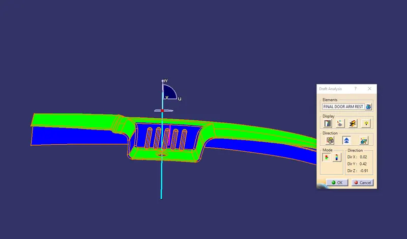
Side-core Tooling Axis Draft Analysis-
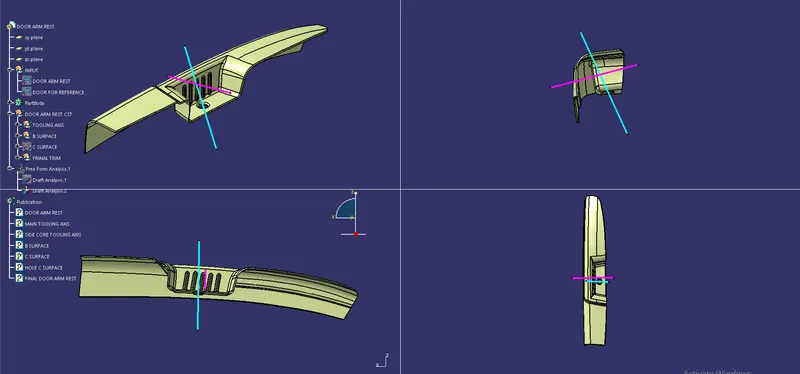
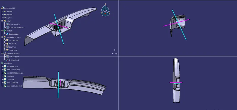
ORIENTATION (ISOMETRIC, FRONT, SIDE, TOP)
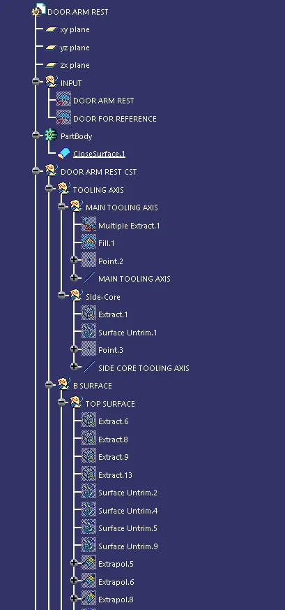
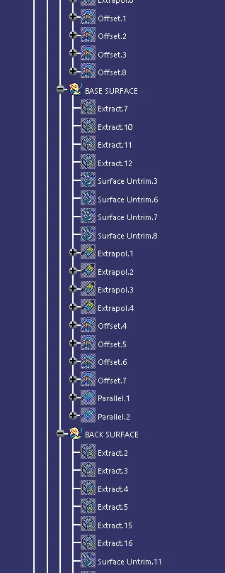
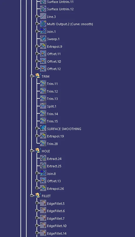
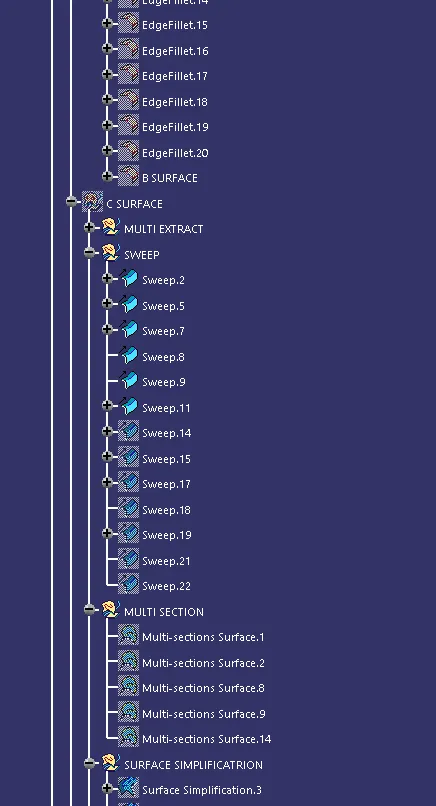
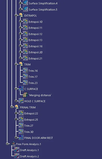
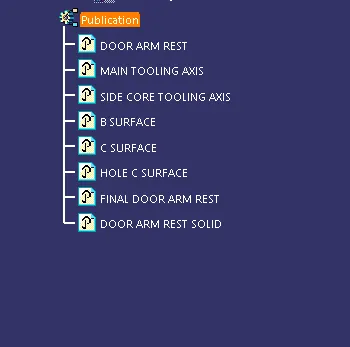
TREE STRUCTURE