Week 8 - Challenge 4 - Coin Holder Design
AIM:-
Create the Coin Holder Plastic component through the given Class-A surface. To begin with, the tooling axis for the given Class-A Surface should be created meeting the requirements of the draft angle and at the end perform the Draft analysis on the model.
Take the Thickness of the component to be 2.5 mm
OBJECTIVE:-
1) Creat a Tooling Axis
2) Create Class B and Class C surfaces according to the class C surface.
3) Perform draft analysis on both Class A and Finla component.
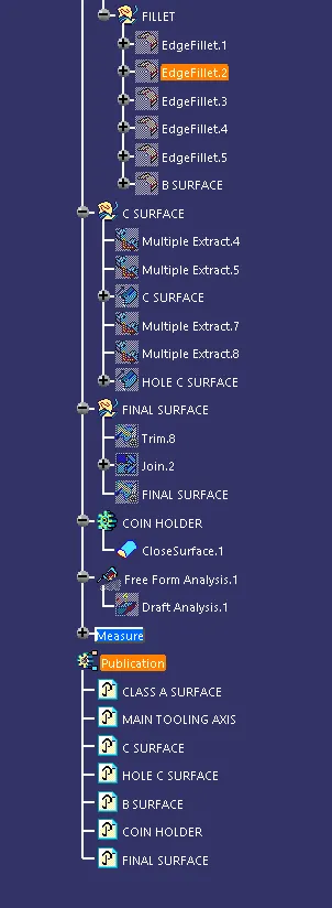
4) Maintain Proper Tree Structure.
5) Use Puclication option to public surfaces and tooling axis.
PROCEDURE:-
STEP 1:-
First step is to insert the class A surface into CATIA V5 and then analyze tooling for the door arm rest.
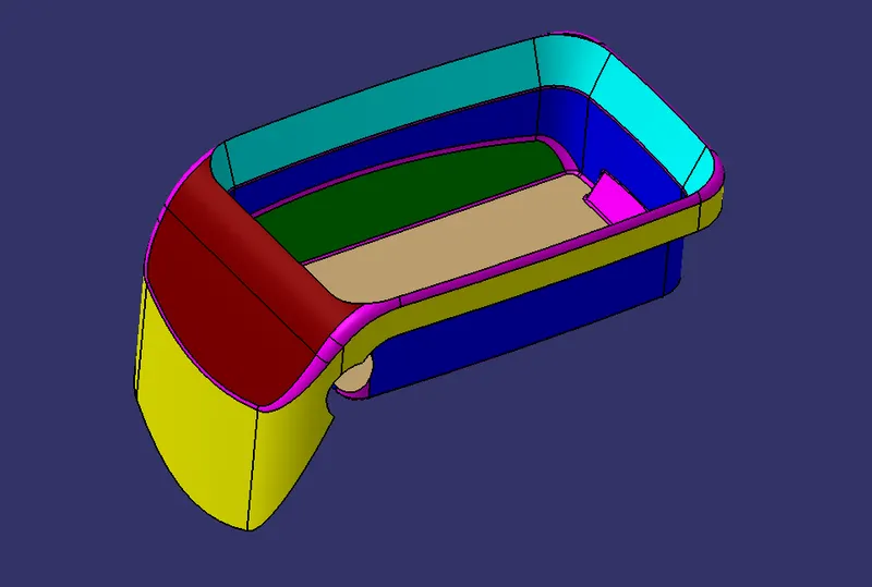
Then analyze the Class A surface for closed boundry use boundry defination as shown below.
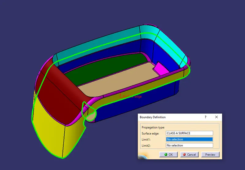
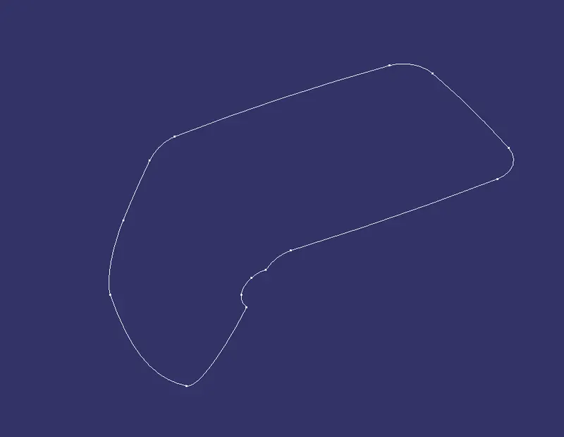

STEP 2:-
CREATING A TOOLING AXIS
Extract the base surface and create a point on it.
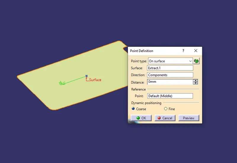
Then create an axis system on the point.
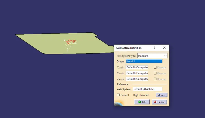
now we create an intersection between base surface and bisecting plane so that wee can clearly visualize the tooling direction in which core and cavity is open.
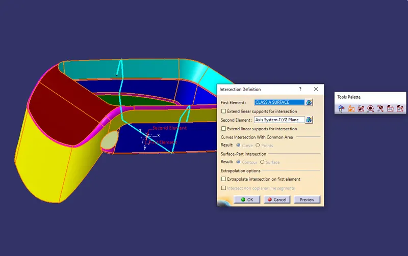
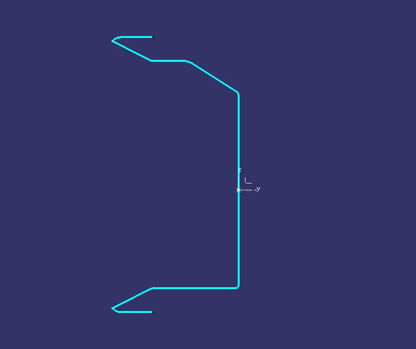
From the intersection we can see there is zero angle of draft.
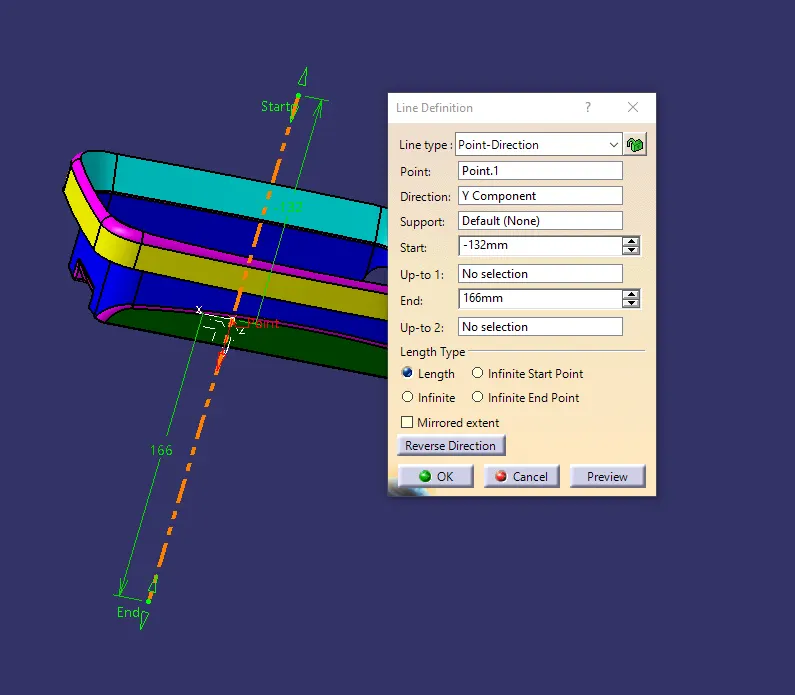
In this case the Tooling axis will be normal to surface at the center of it as shown below./
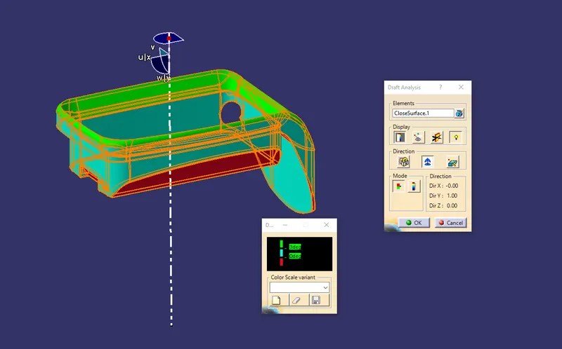
Then we perform draft analysis on the class A surface as shown below where you can see minimum draft angle should 3mm.
STEP 3:-
CREATE CLASS B SURFACE
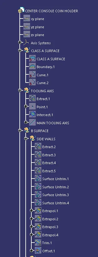
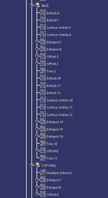
- For creating Class B surface first extract the side walls, base for the coin holder from the Class A
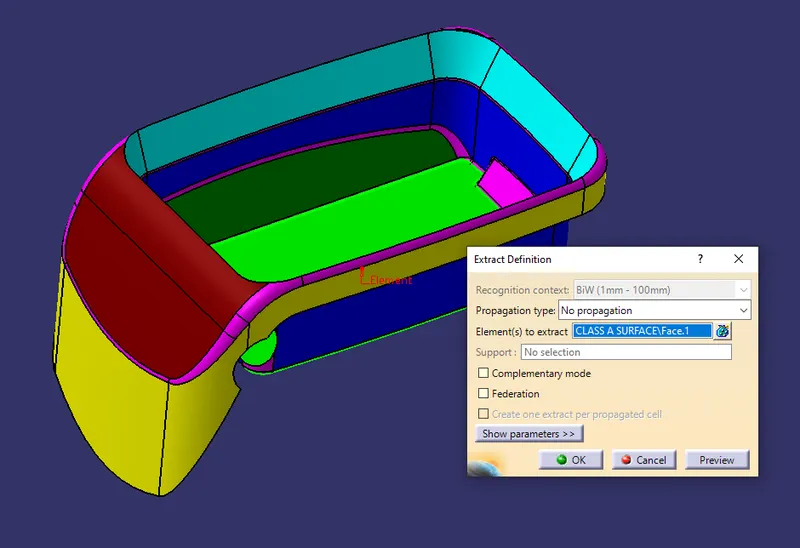
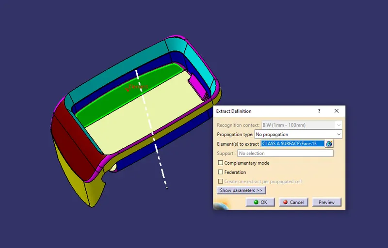
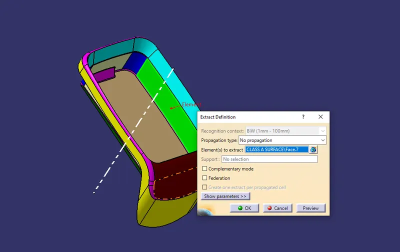
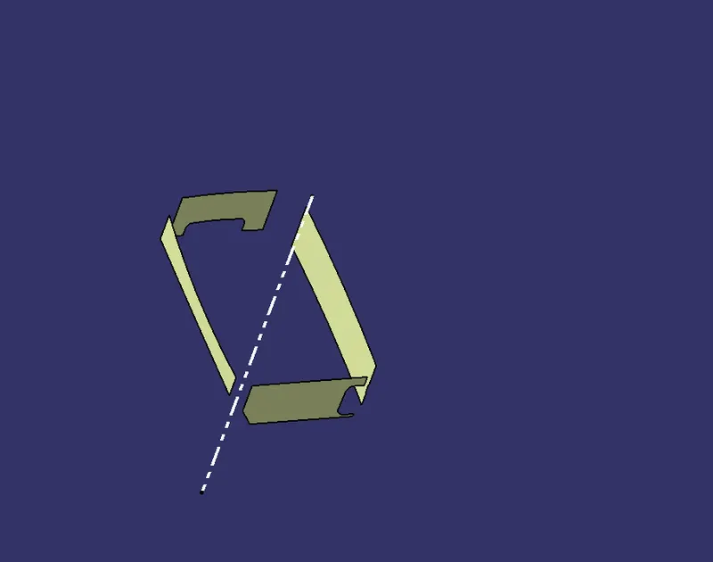
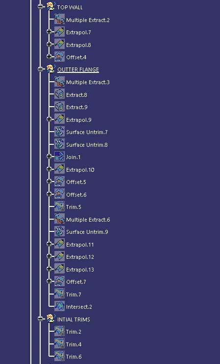
- Then Extract the Flange and outer flange as shown below.
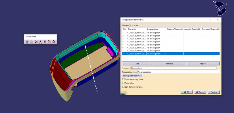
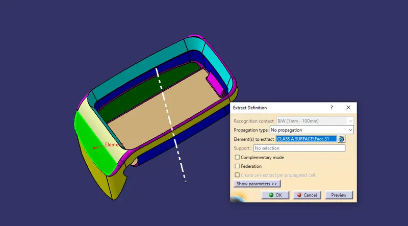
- Also extract the top walls as shown below.
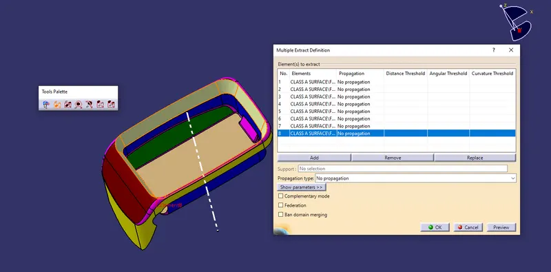
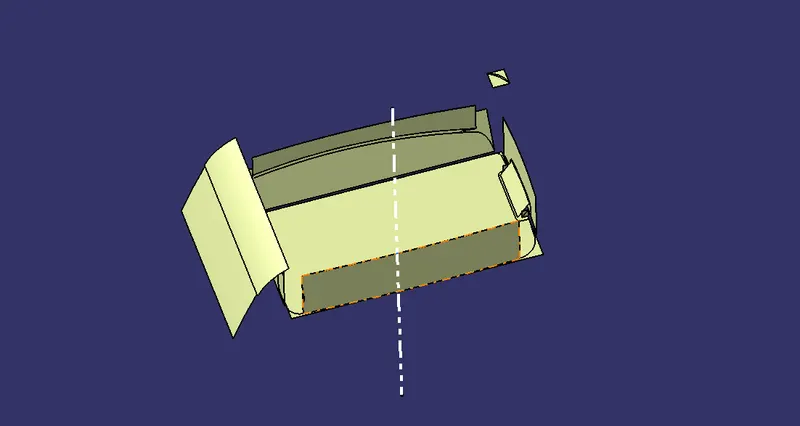
- Next will be untrim and extrapol the extracted surfaces as much require for triming as shown below.
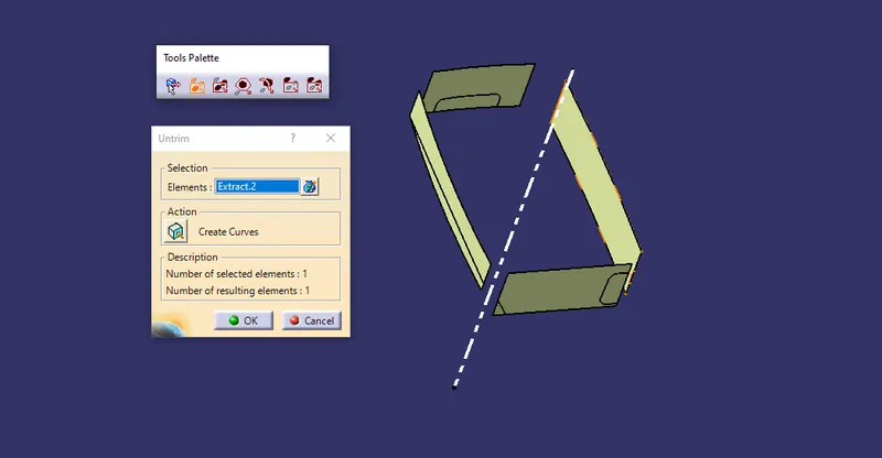
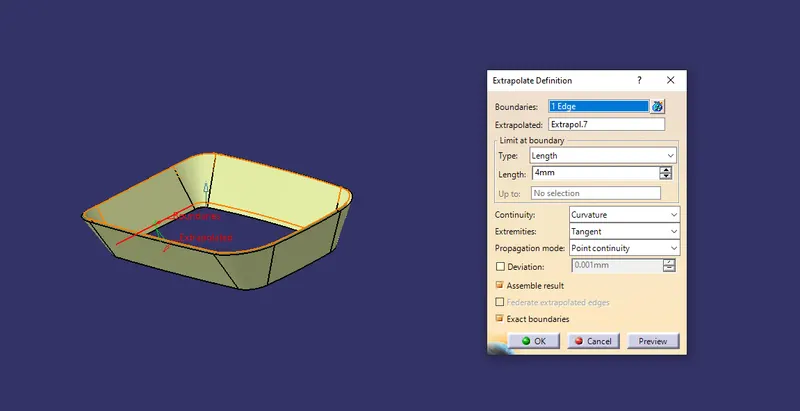
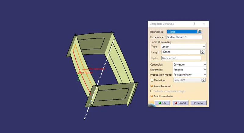
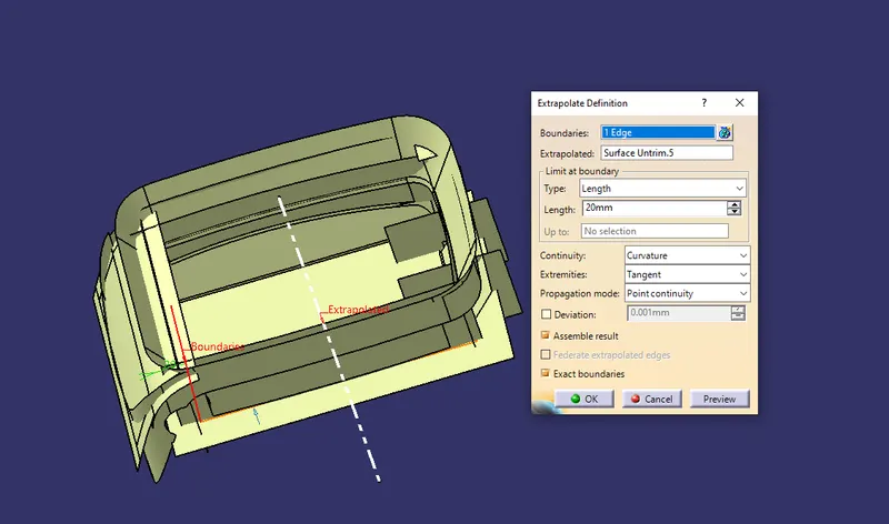
- TRIM
Trim the surfaces as per requirement of the class B as shown below.
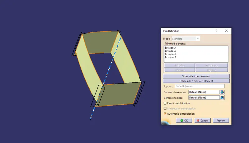
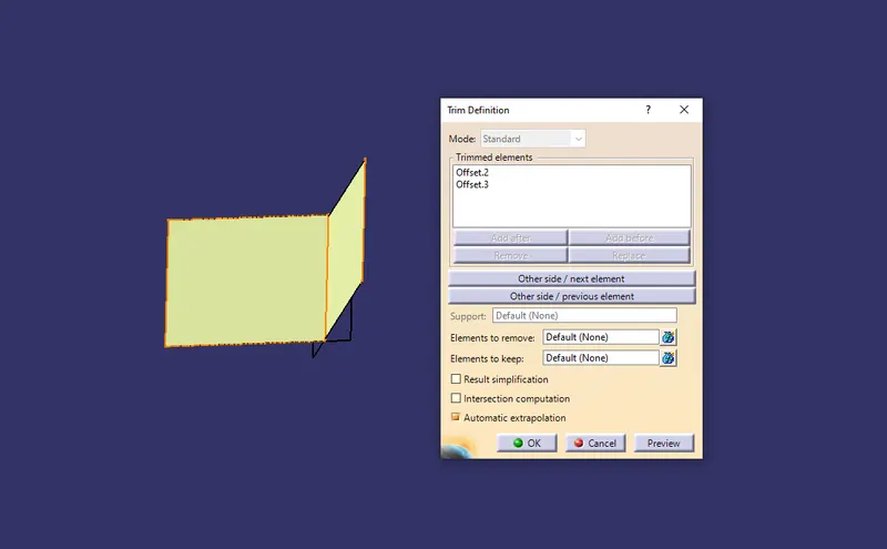
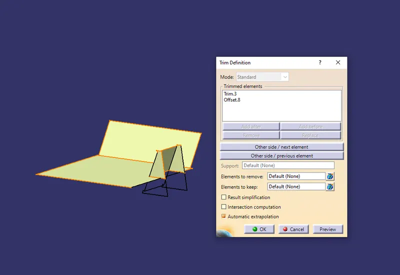
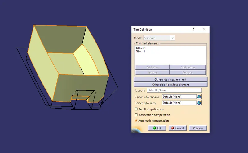
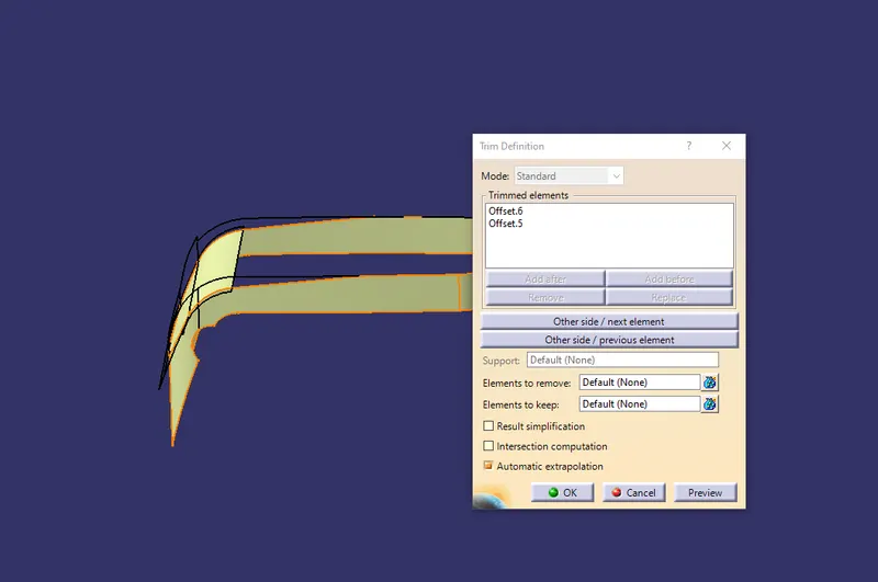
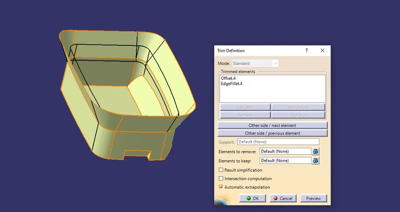
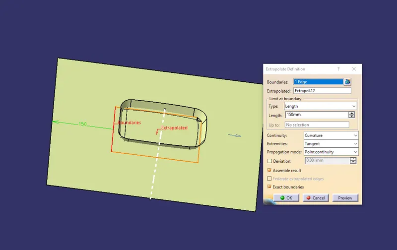
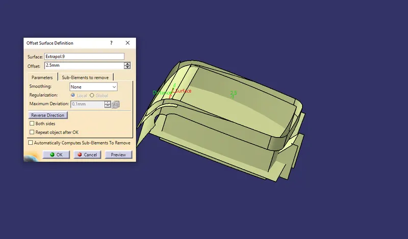
- OFFSET
Now offset for 2.5 mm all the surfaces those are trimmed and extracted foorm Class A surface for creating Class B as shown below.
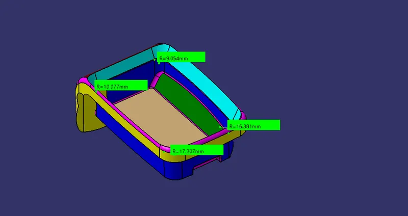
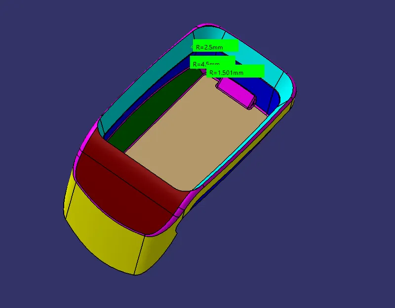
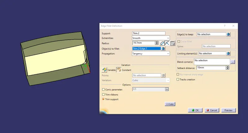
- FILLET
This step is for filleting the sharp corners of Class B surface by mesuring the fillets from given Class A and some of the common fillet willbe 2mm as shown below.
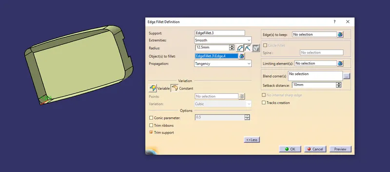
- trim corners of top walls as shown below.
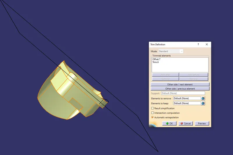
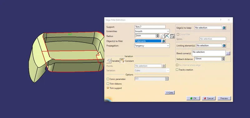
- This is Class B surface .
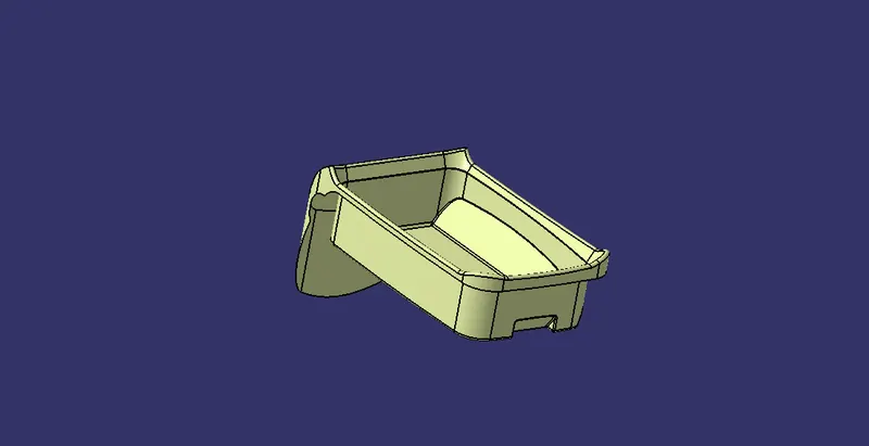
STEP 4:-
CREATING CLASS C SURFACE
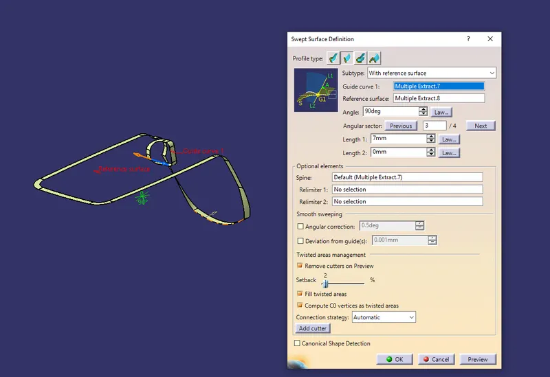
- For Class C creation extract the boundries of the Class B and Class A . Then use those exract as guide and reference surface in the sweep command with angle of 90 degree as shown below.
STEP 5:-
FINAL SURFACE
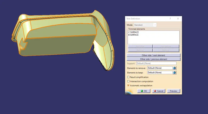
- Now trim both Class B and Class C with each other.
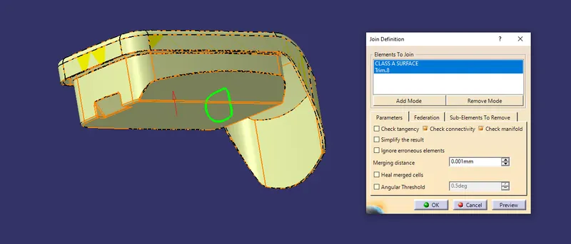
- Next using join command join Class a and trimmed surface.
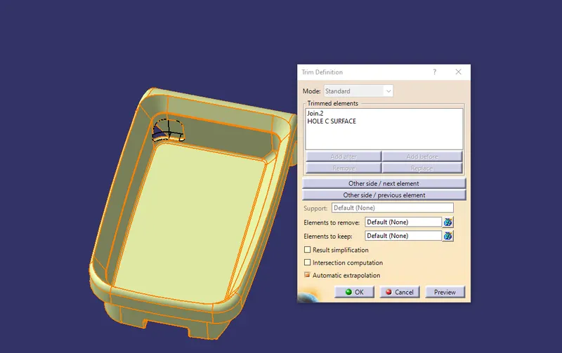
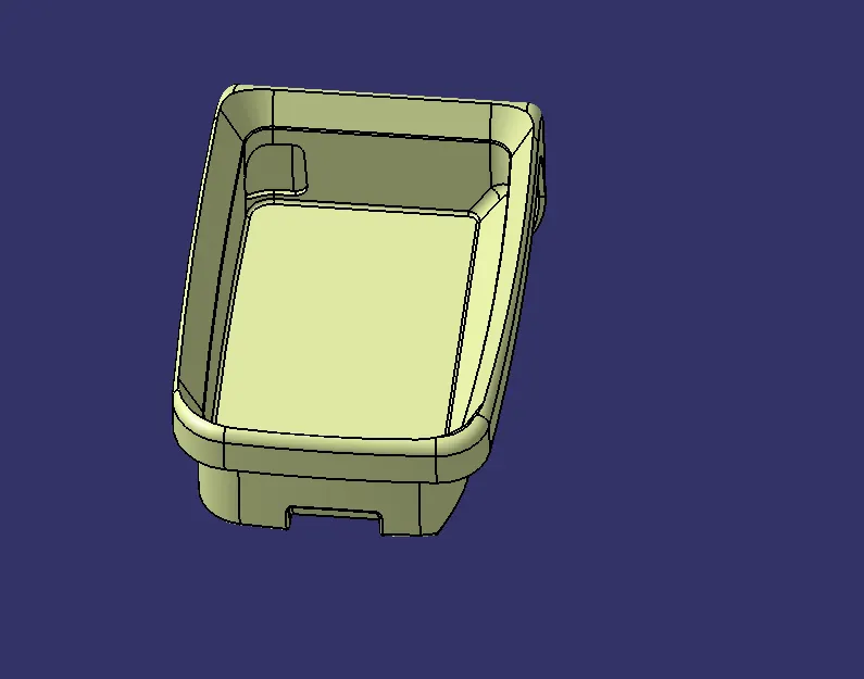
-Lastly trim C Surface of the hole with the joined surface as shown below.
STEP 6:-
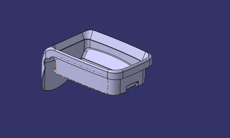
Create solid out of the Final Coin Holder Surface as shown below.
STEP 7:-
DRAFT ANALYSIS
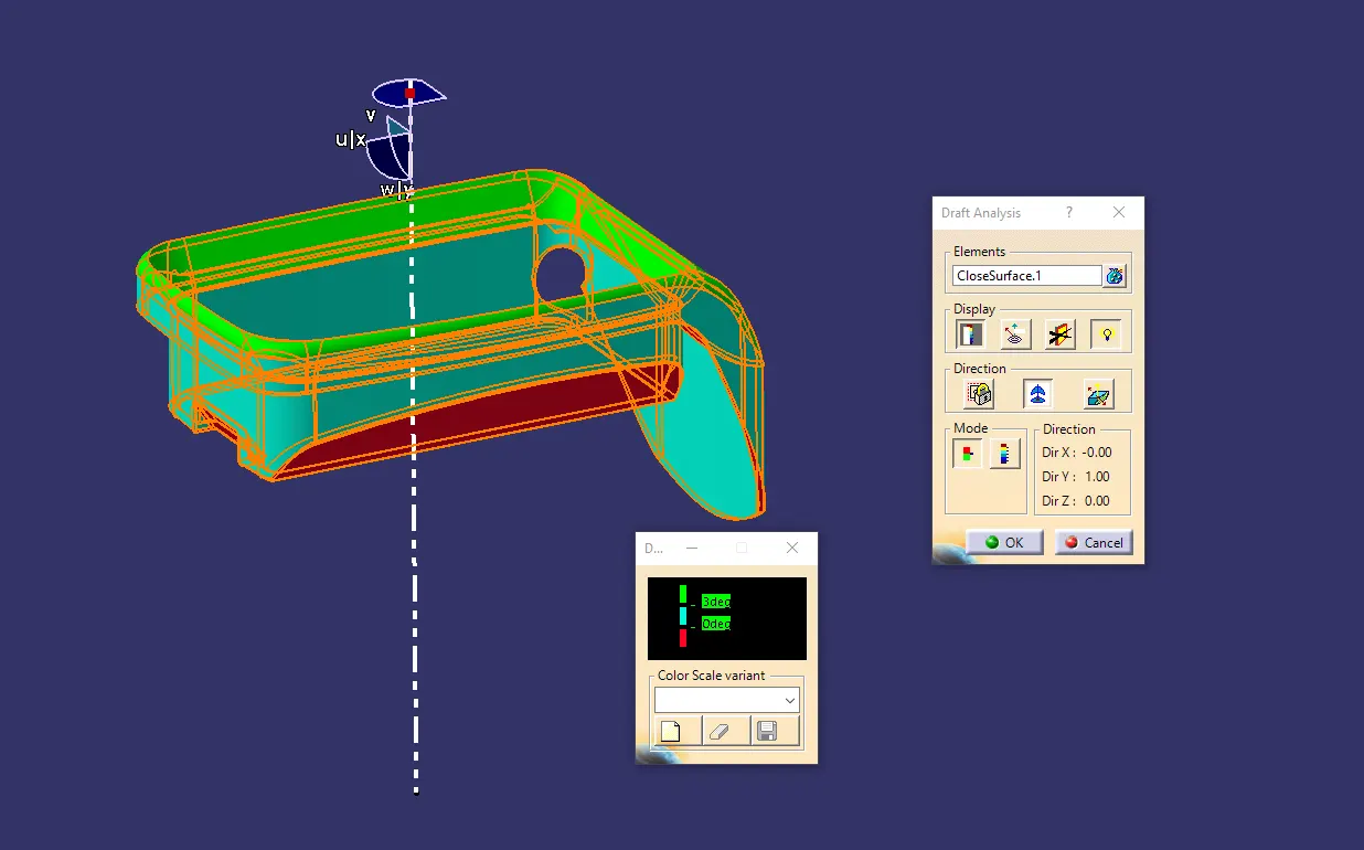
- For the Draft Analysis firstly customize the view parameter to change the mesh shading to the material.
- Then Go to Tools > Insert > Analysis > Feature Draft Analysis.
- Drag the Compass and drop it on Tooling Axis from the above dialogue box.
- Choose Solid Body as the Element.
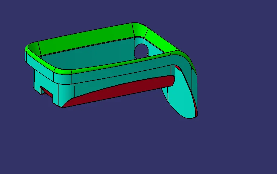
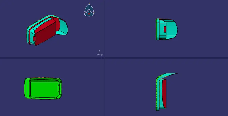
- The Green region has minimum draft of 3 degree and the Red region has a negtive draft (this is beacuse of the reverse direction). Blue is for the 0 degree draft.
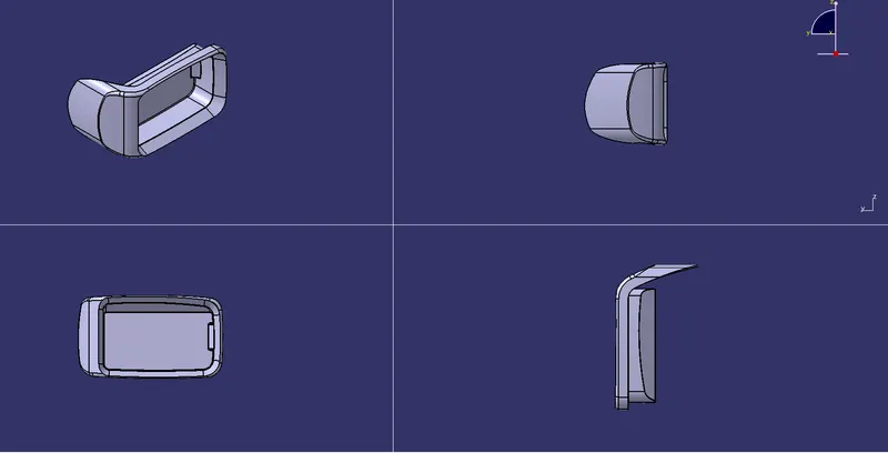
VIEWS(ISOMETRIC, FRONT, TOP, SIDE):-
TREE STRUCTURE:-