Week 8 - Challenge 3 - Switch Bezel Design
AIM
Create the Switch Bezel Plastic component through the given Class-A surface. To begin with, the tooling axis for the given Class-A Surface should be created meeting the requirements of the draft angle and at the end perform the Draft analysis on the model.
Take the Thickness of the component to be 2.5 mm
OBJECTIVE
1) Create a Tooling axis meeting the requirements of the draft angle.
2) Create B surface and class C saurface.
3) Perform draft analysis on the component to ensure proper draft angle.
4) Ensure proper tree structure
5) All sketches shold be created under geometrical set.
PROCEDURE
Step-1
Insert the class A surface into CATIA V5.
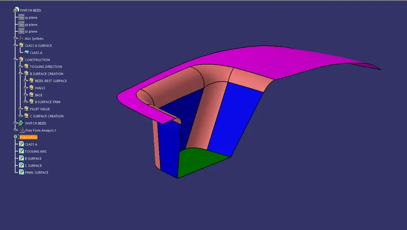
Then check for boundries to make sure their is no gap in the class A surface.
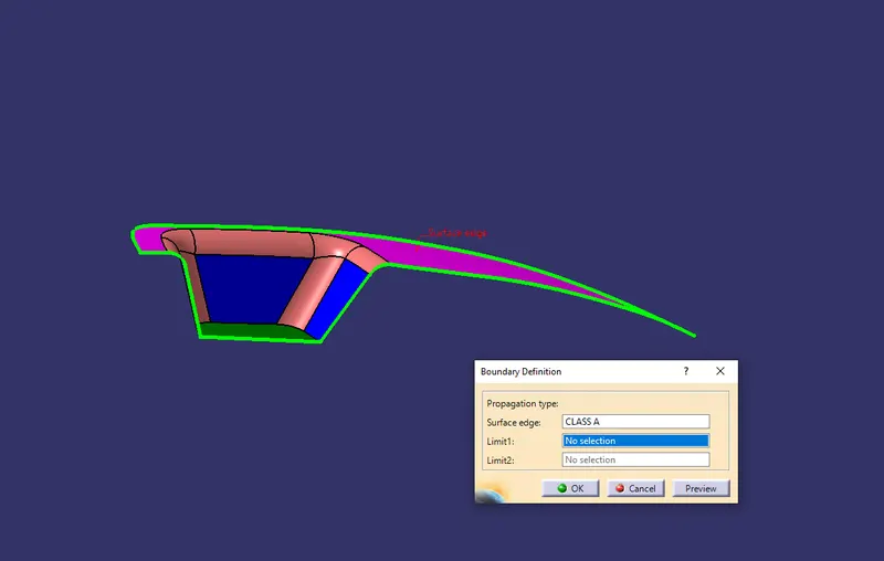
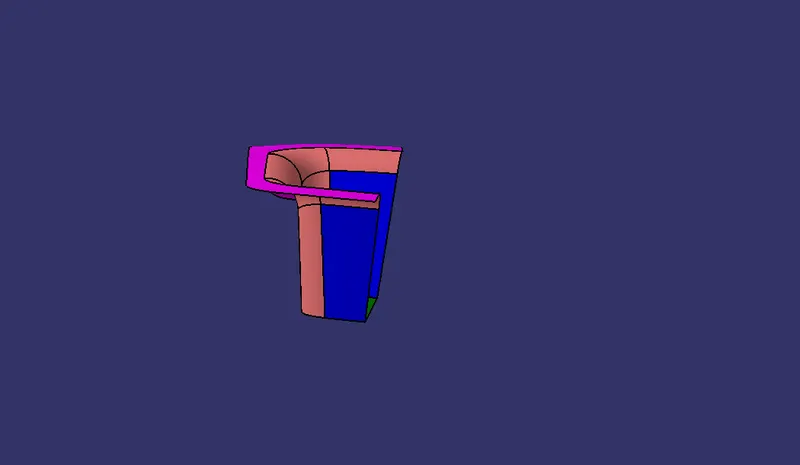
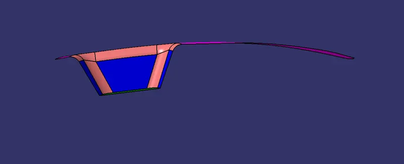
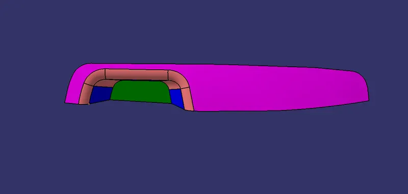
After that check the directions to ensure wihich is clearing for the class A.
Step-2
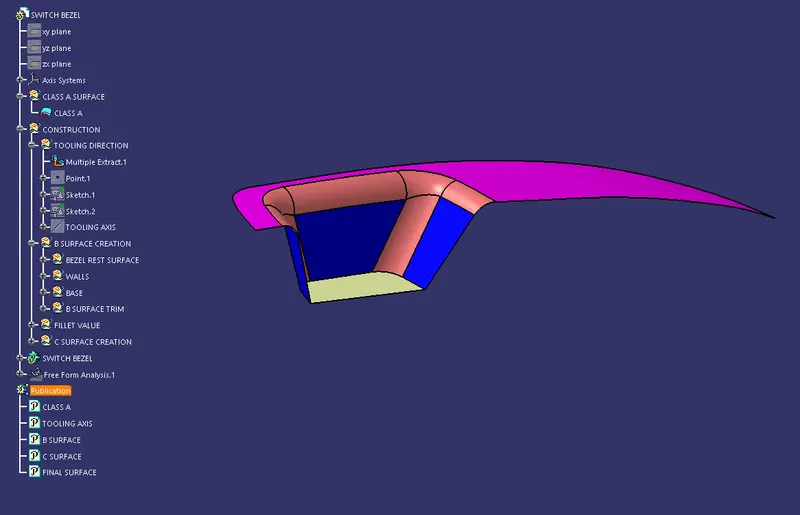
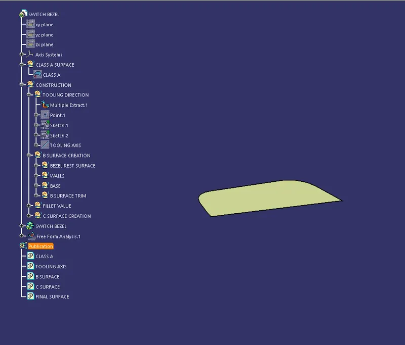
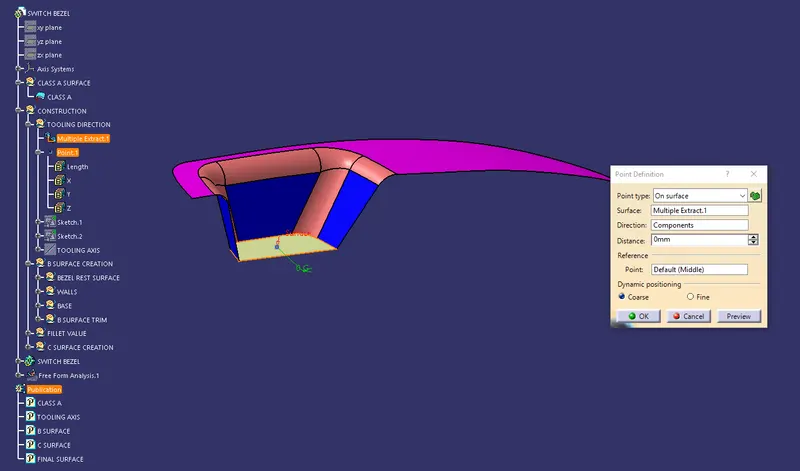
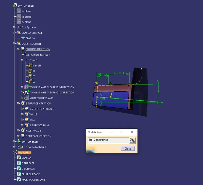
After conforming the direction that the class A is clearing in Z-direction. Then extract the pocket base for creating a point reference for tooling axis as shown below.
Step-3
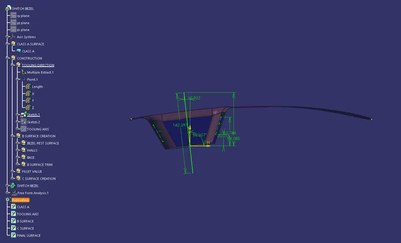
Creating Tooling Axis
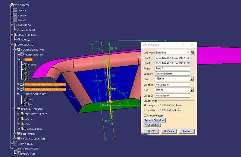
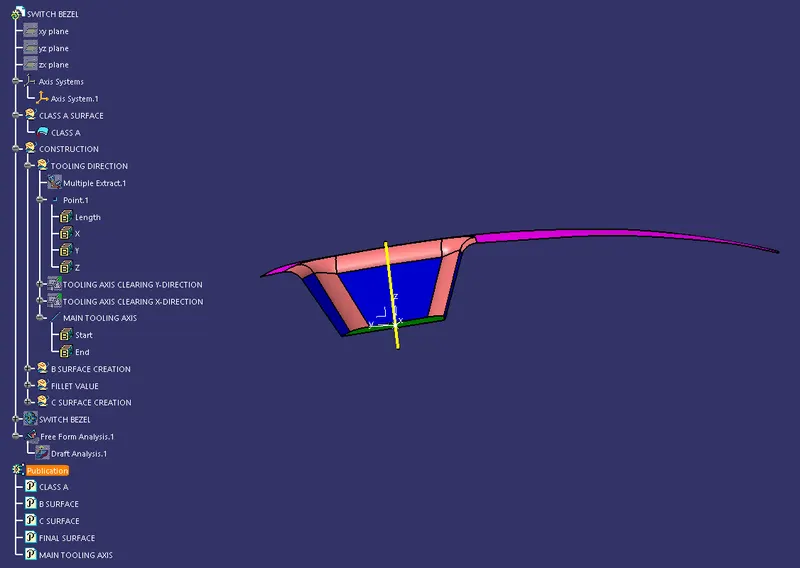
Next create the dummy tooling axis in Y-direction and X -direction. Then using bisecting method between these two tooling axis we would create a the Main Tooling Axis in Z- direction as shown below images.
Step-4
Now for create the B-surface we need extract required flat surfaces from the Class-A as shown below.
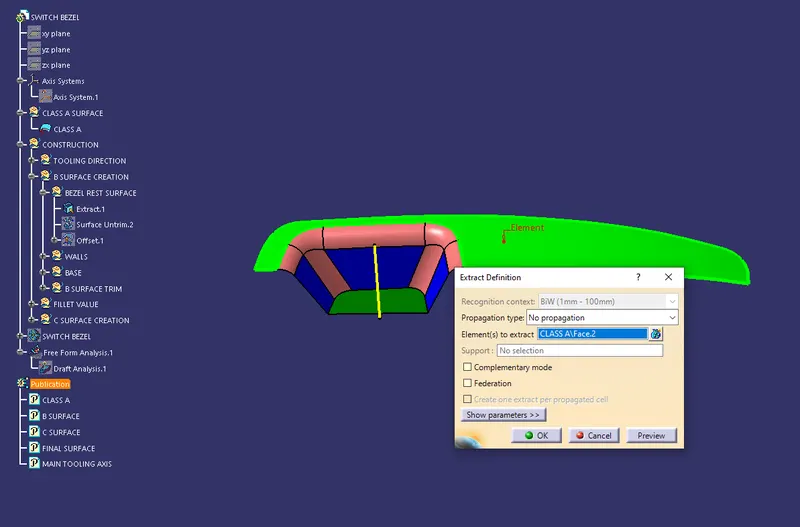
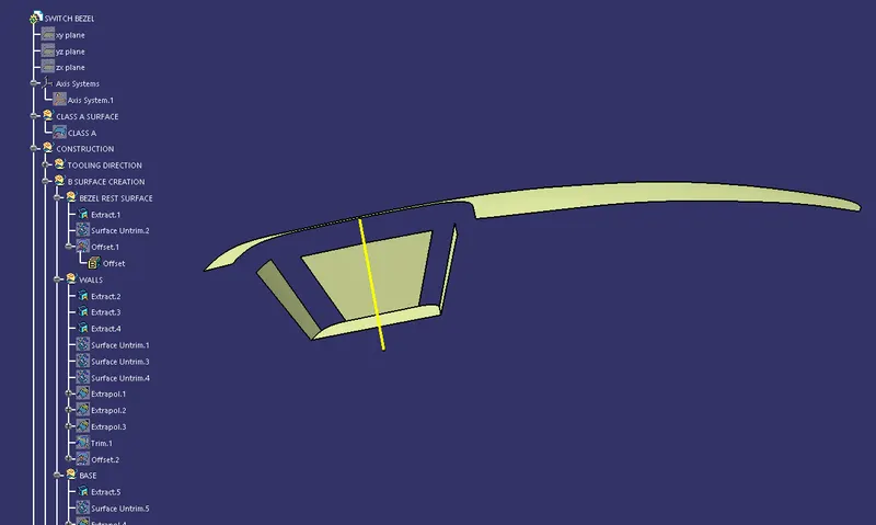
Then we need untrim the surfaces we have extracted before using surface untrim as shown below.
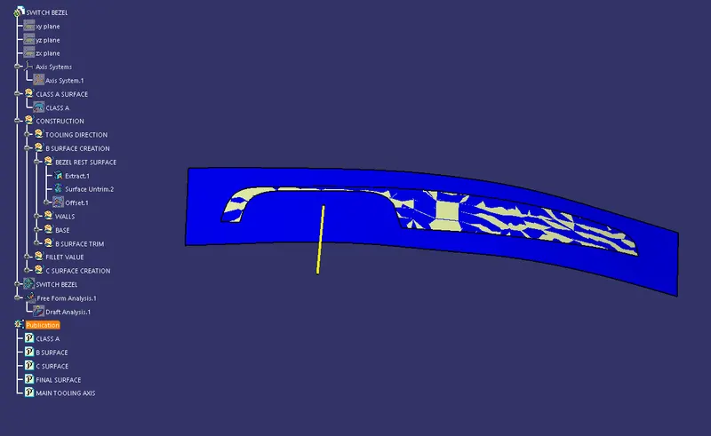
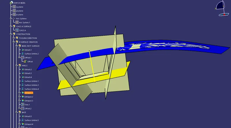
After that extrapol the surfaces which are needed because B-surface should be bigger than A-surface.
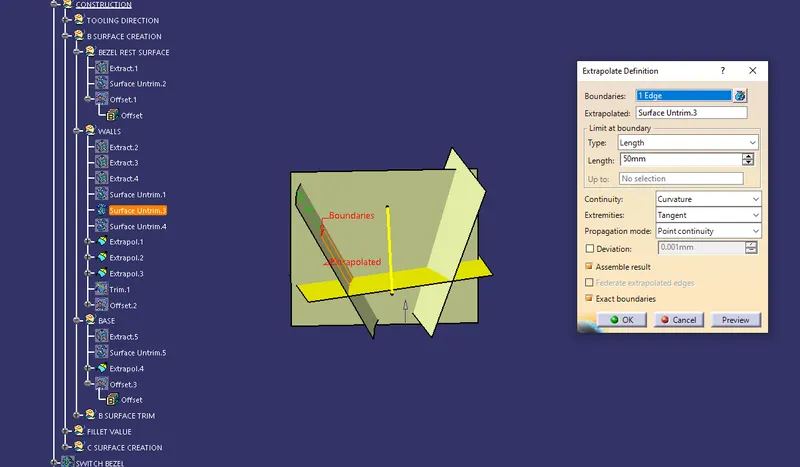
Next step will be trim extracted pocket walls with the base as shown below.
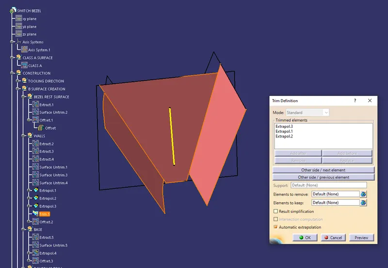
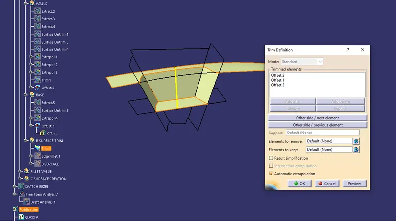
Step-4
Now take measurements of the filletes so that we can apply it on B-surfaces as shown below.
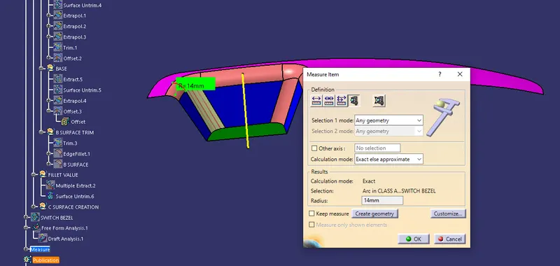
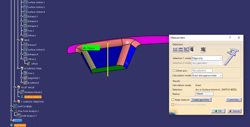
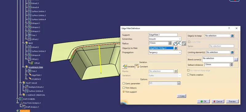
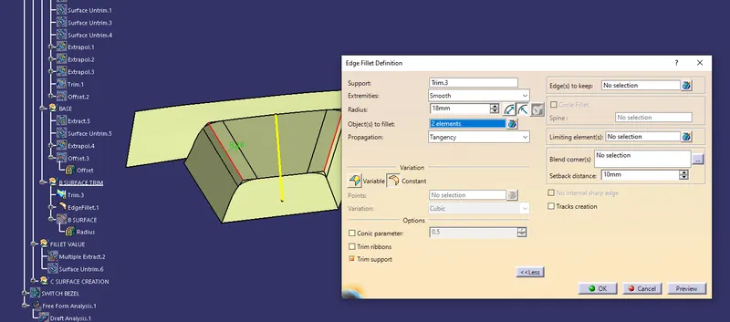
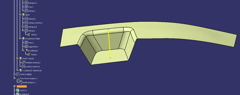
Step-5
Creation Of C-Surface
For creating C-surface extract the boundry of the A-surface first.
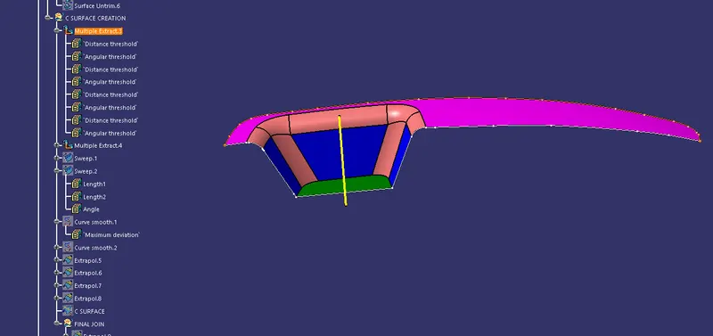
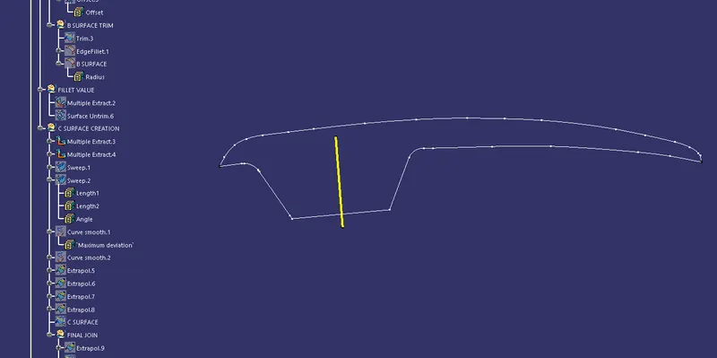
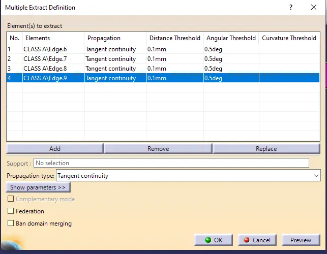
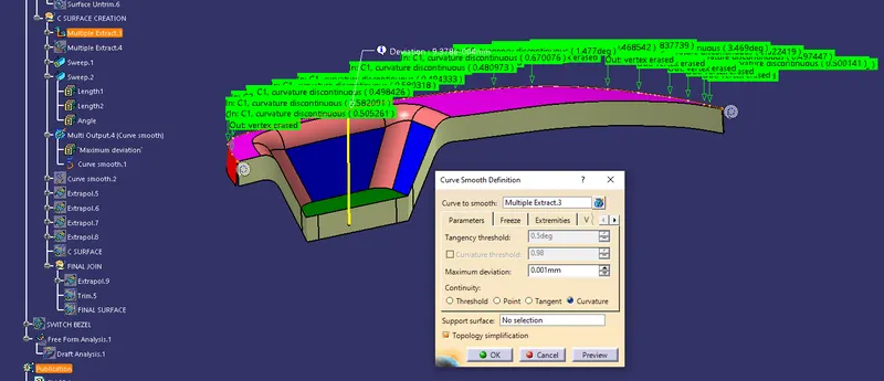
Then use curve smooth on the boundry for avoiding error at time creating C-surface.
Step-6
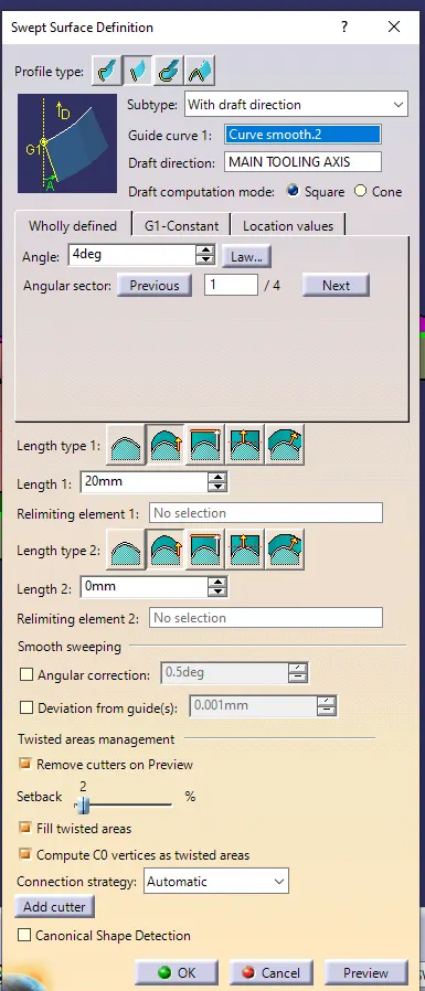
Using sweep operation create the C-surface by taking boundry as a guide curve and Main Tooling Axis as draft direction. Now give the draft direction toward outward and the minimum draft angle should be 3 degree as per tthe design rules. But in the below image I have given 4 degree in the sweep operation whic is within design rules.
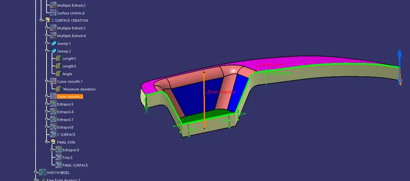
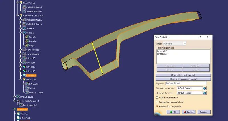
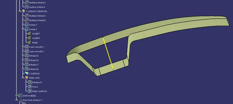
Now trim the surfaces we have created using sweep and which will be our class-C Surface.
Step-6
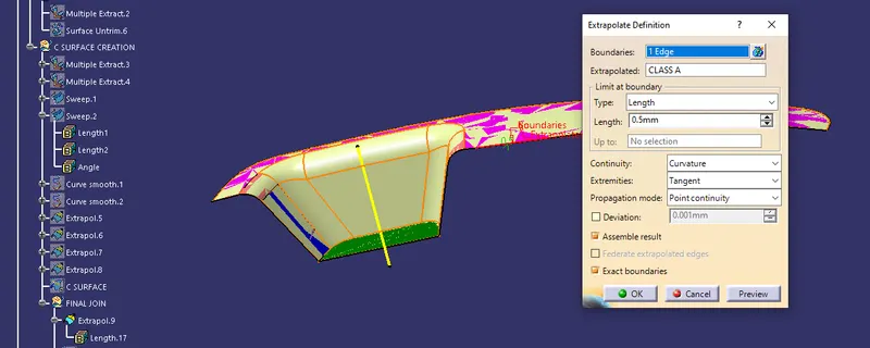
Next step will join A-surface and C-surface together by trim them wuth each ither as shown below images.
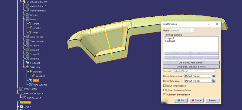
Step-7
Creation of Close Surface
For create close surface we need trim the B-surface with the joined A and C surface.
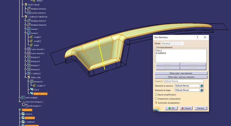
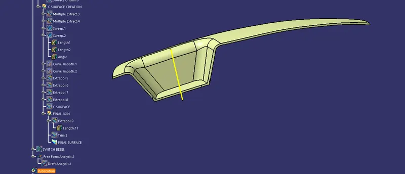
Step-8
Create a solid body out of the close surface in the part design as shown below.
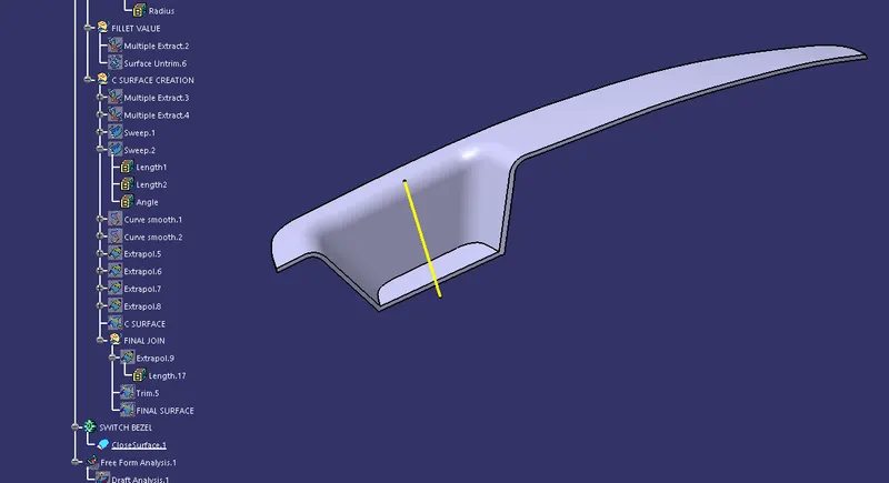
Step-9
Draft Analysis
Now perform draft analysis on the component for that Go to menu bar > select Insert > Analysis > Feature Draft Analysis.
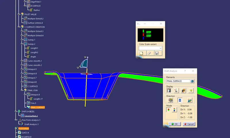
Next place the compass onthe tooling axis and lock it. Then there will be a red pont when you drag pointer on the surface of component.
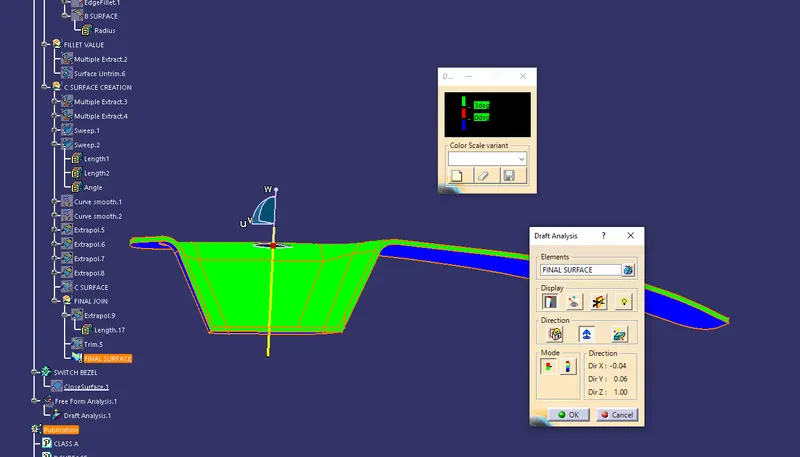
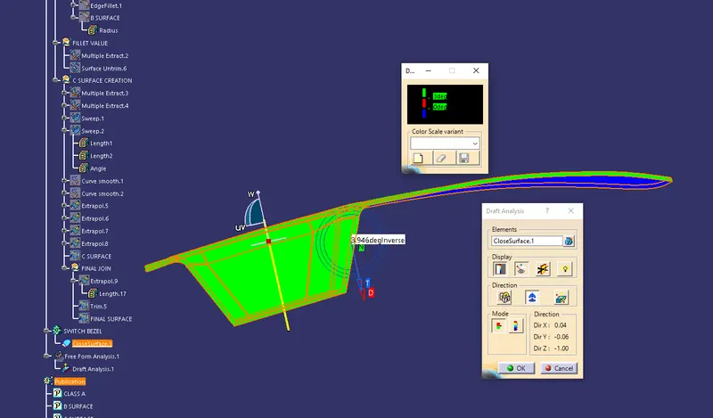
After that click on the surface of the component to see draft analysis. Then on dr4aft nalysis tab there is a display usder which there is color scale variant tab click on that see the draft angle. The minimum draft angle should be 3 degree as shown below.
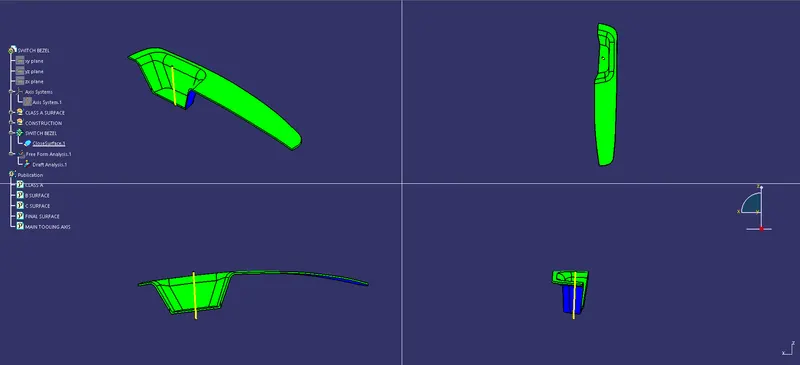
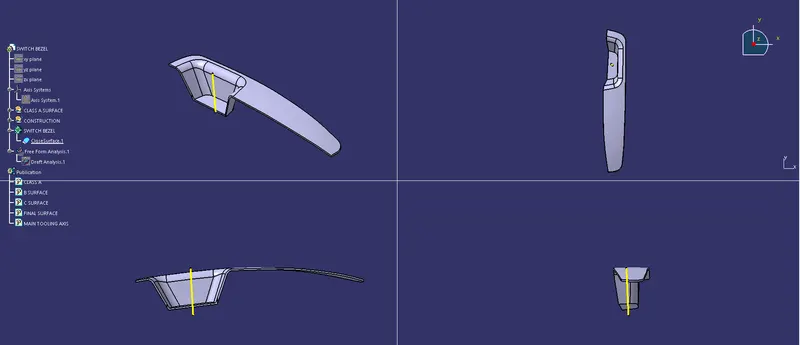
VIEWS (ISOMETRIC, FRONT, TOP, SIDE)
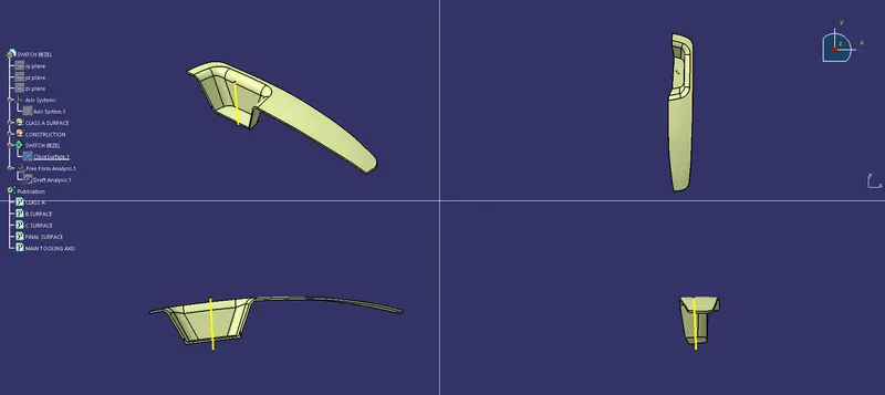
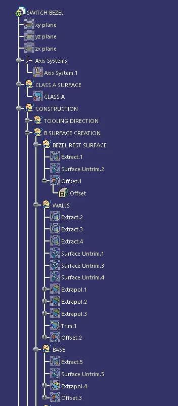
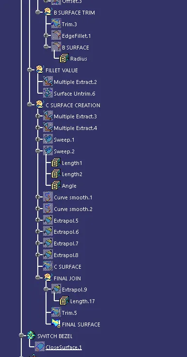
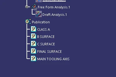
TREE STRUCTURE