Week 8 - Challenge 1 - Base Bracket Design
Aim :- To design the Base Bracket plastic component through the given Class-A surface.
Raw material used in Base bracket of plastic component:
- Thermoset plastics
DESIGN PROCEDURE:
- To setup the class-A surface and to creating a tooling axis
- add draft angle
- To create a base surface of model
- To create a B-surface
- To create a C-surface and surface model of a base bracket
- To use close surface for creating a solid part model
CLASS A SURFACE:
Define: Class-A is a term used in specifically in automotive design. It describes the final production surface data for the aesthetic parts of the car. The term 'Class A' is often misunderstood, but it's generally seen as the 'Holy Grail' of surface modeling.
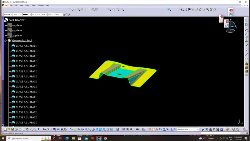
Tooling Axis:
The direction in which the mold or core and cavity opens is the tooling axis.
- Tooling axis can be classified into two methods
- Direct method
- Bisecting method
In this model we use direct method based on the requirement.
- First ensure the class-A surface is properly joined and has no discontinuity on it. For this we can use boundary command or join command.
- Analyze the model manually or visually to see which direction is most suitable for tooling axis.
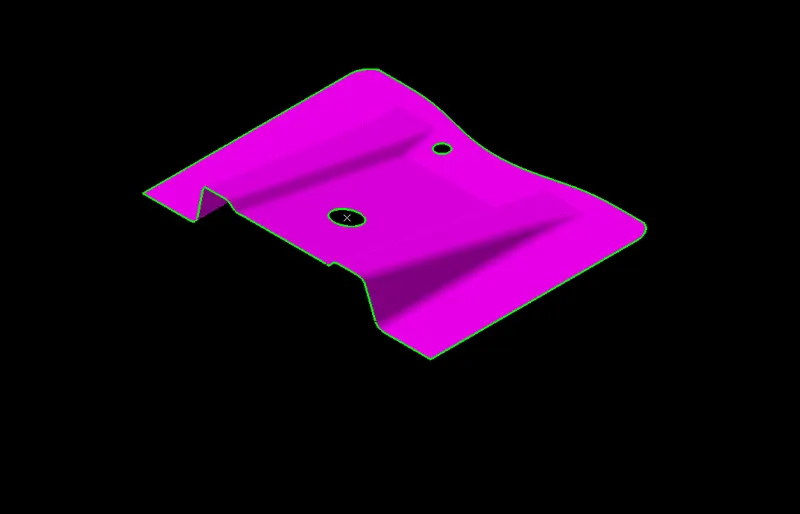
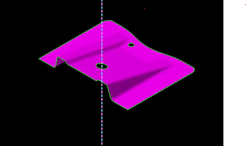
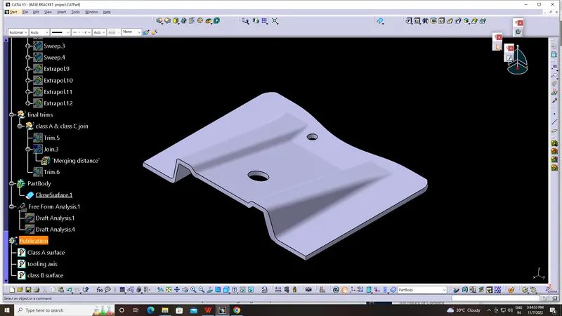
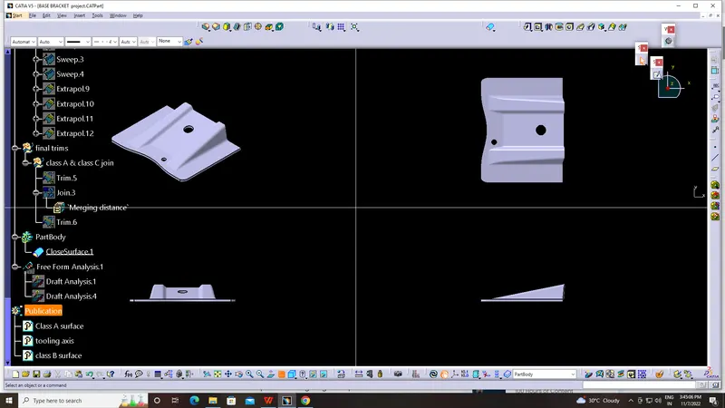
- As in 3D view we can see 2 holes and a flat surface, we can directly take the tooling axis perpendicular to that. But to be sure,let us analaze from all the views. The below images of the front side and top views shows the areas that we have to keep in mind while choosing tooling axis. As from X we cannot see one hole so we cannot take axis along this. In Y we cannot see any holes so here too we cannot take tooling axis. But in Z we can see 2 holes and flat surface so we can take tooling axis.
DRAFT ANALYSIS:
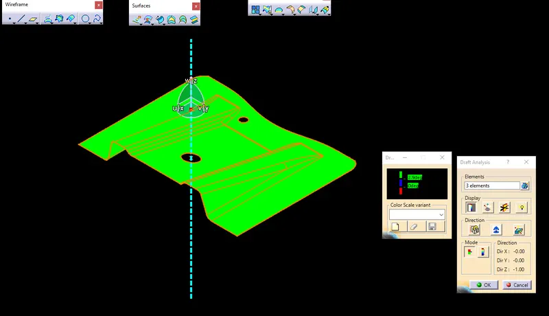
The draft analysis technique is used to analyze whether our part model created is manufacturable based on the draft condition applied.
- Go to insert< analysis< feature draft analysis.
- Align the tooling axis with the compass.
- Click on the surface and see that the surface is within the permissible limit of the draft values.
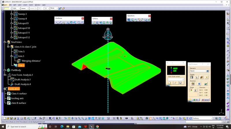
- The surface should be green and in the column proper value (3deg) should be inserted.
CLASS-B SURFACE:
Class B surfaces are the secondary surfaces that you can see sometimes, but are less important.
Initially extracting all the flat surfaces.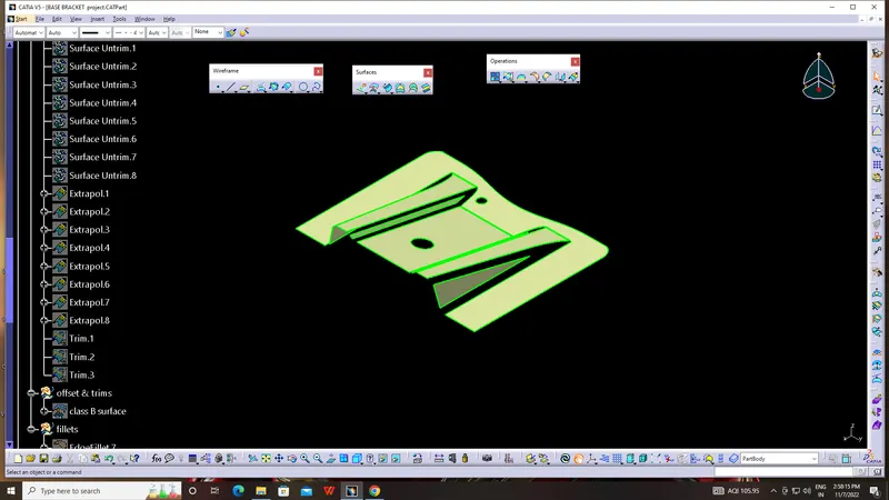
Then untrimed all the extract surfaces by using untrim command.
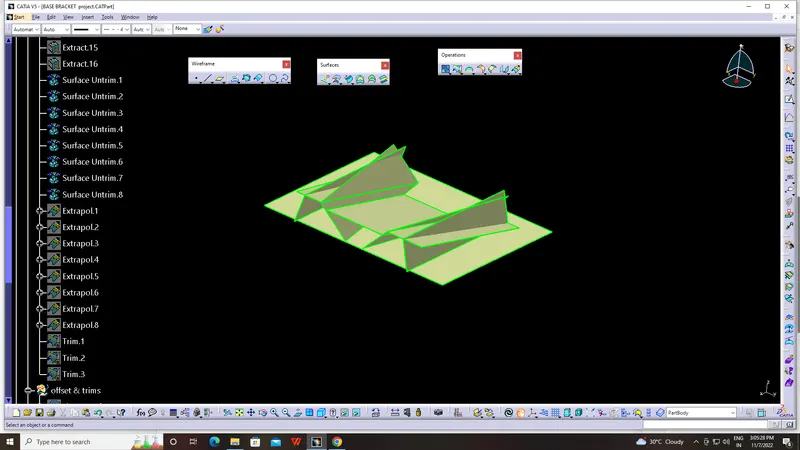
Then perform Extrapolate inorder to increase the length
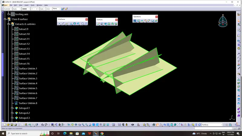
Now trim the surfaces to required surface.
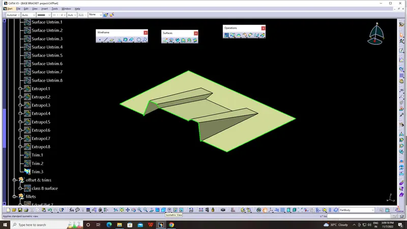
Now offset the Class B surface from the class A surface to the required dimensions by using offset command.
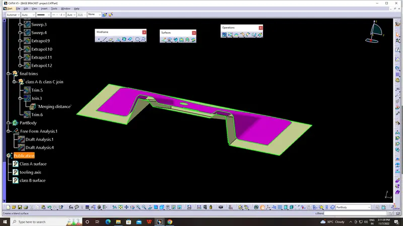
Now fillet the surface to required amount
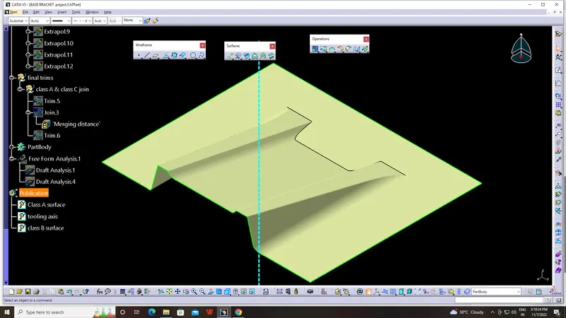
Class C Surface:
The Class C finish allows more imperfections than Class A or B. Class C is often specified for interior surfaces not readily visible, surfaces that will be covered by another part when assembled, or surfaces which the Customer feels do not need to meet a high cosmetic finish.
- Unhide the A Surface to Take a boundary as a reference to make C surface.
- Go to sweep line-> with draft direction 3 deg draft angle downward outside.
- And Same thing to do for the 2 holes.
- Join all of them to make C Surface.
- Then Publicize it.
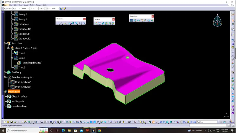
- Take a Joined part C Surface And B Surface to Trim unwanted surfaces to make it as a Solid part.
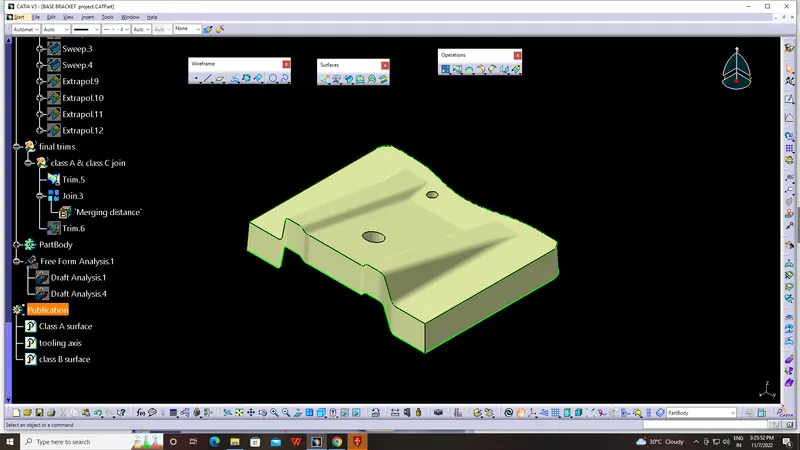
Then unhide the class B surface trim the required dimensions.
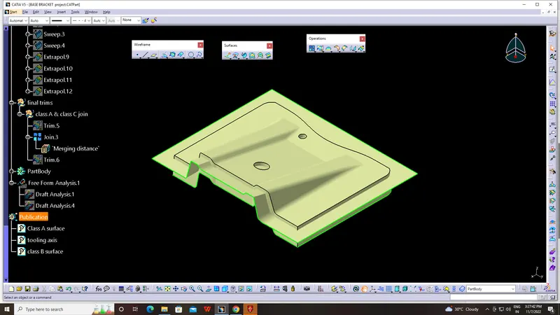
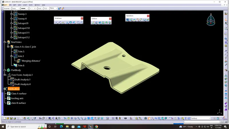
Final draft analysis:
Again draft analysis conducted to the final output.
Isometric view:
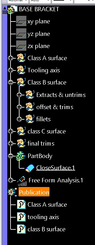
Tree structure: