Week 9 - Project 1 - Door Trim Lower with Engineering Features
AIM
This Report aim is to perform draft analysis for the given surface by defining a tooling direction appropriate to the shape of the surface and also to create the class-B,class-C surfaces and final closed body with the help of given Class A surface of Door trim lower and to create heat stakes and 4 way loactors based on design rules.
THEORY
Class A surface:
This is the styling surface which provides the aesthetic features of a component. A designer starts the design of component from a class A surface.
Given class A surface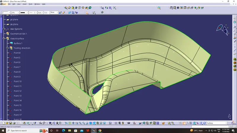
Class B surface:
Class B surface is obtained by offsetting the class A surface by the component thickness value. This B surface contains all the engineering features of the component. So it is also called as Engineering Surface.
Class C surface:
Class C surface is created along the tooling direction of the component and it connects the class A and class B surfaces.
Tooling Axis:
Tooling axis is the direction in which the part is released from the mould.
PROCEDURE
Defining the tooling direction
Ideal tooling direction has to be the direction in which most of the features can be easily cleared. In this case the initial tooling direction can be assumed in the direction perpendicular to the flat surfaces and the surfaces which might be difficult to clear in this direction are identified and the initial tooling direction has to be modified accordingly. But in this case the flat surfaces and the critical surfaces are perpendicular to each other. So, the initial tooling direction can be taken as the final tooling direction.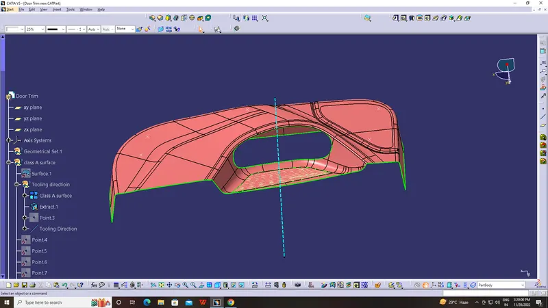
Creation of class-B surfaces:
B surface is created by offsetting the class A surface by 2.5mm and if there are any surfacesnot offsetted then they will be created by using multisection surface or sweep command.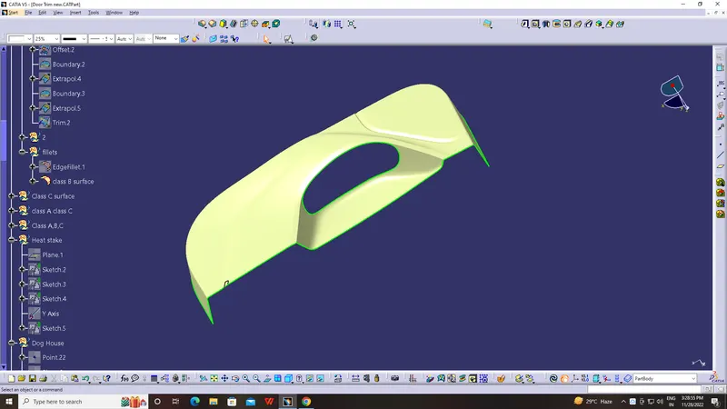
Creation of Class-C surface:
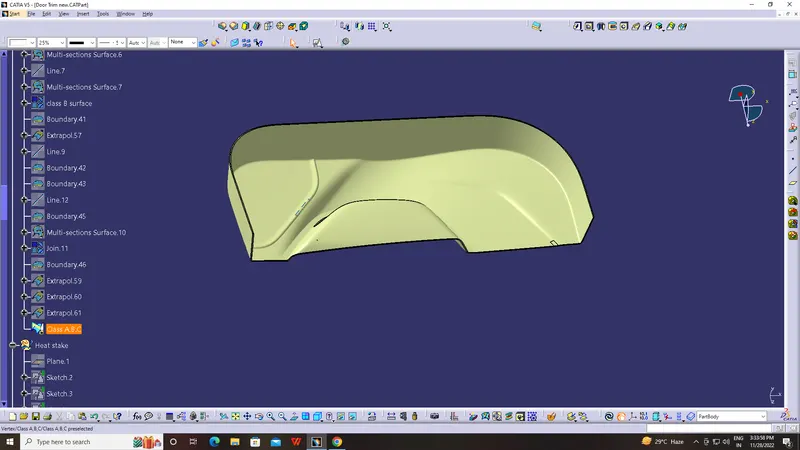
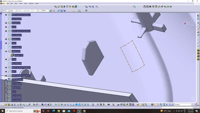
C surface is created by using boundary of A surface. with the help of sweep command surface is generated perpendicular to the edges of A surface.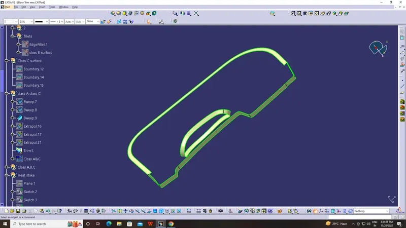
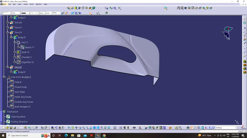
Creation of closed surface:
Heat Stakes:
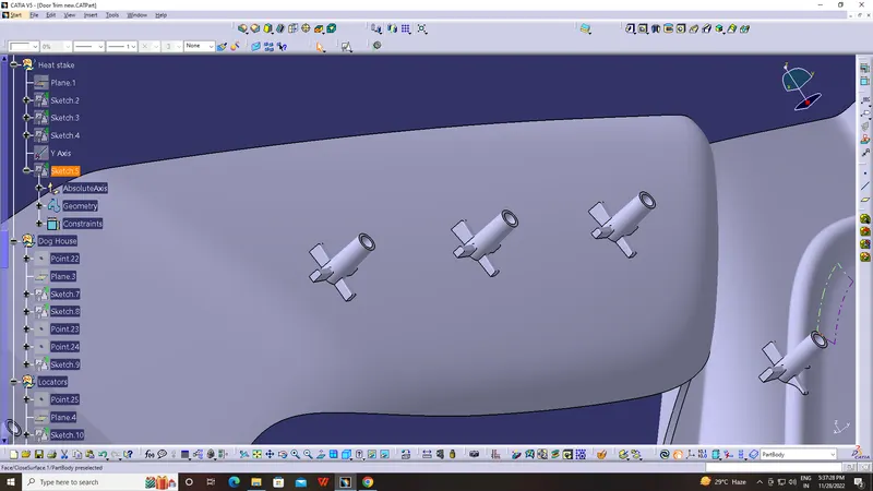
In heat staking, we use local heating and cooling to raise the temperature of plastic components and allow plastic reforming to be carried out.Then fillet is applied to the faces of the rib. As per the design rule, the fillet can be 0.25 mm.These heat stakes will enter the mating component and using a heat staking machine these heat stakes are melted and cooled. When cooled this will get hardened and the two components will stick together. Thus all degrees of freedom are arrested.
Heat stake Design procedure
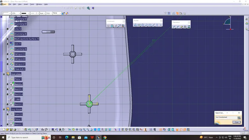
- Using positioned sketch, create sketch of the heat stake profile.
- Pad it with reference to the tooling axis.
- Heat stake height should be lesser than the height of locators provided.
- Thickness should be 40% of the component main thickness to avoid sink marks on the A surface.
- Provide draft angle of 0.5 degrees on both inside and outside walls of the heat stake.
- There should be minimum 50 mm gaps between each heat stakes.
- Create more heat stakes by special copying option and translate it to desired points.
- Then union trim them with door trim part body to get the final component.
Dog house :
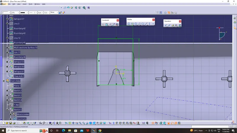
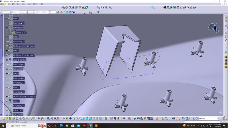
Locators creation
Locators are used when assembling sub parts and are very useful engineering feature for easy way of locating the position of the parts to be assembled
I have created two 4-way locators and one 2-way locator for the given door trim design.
Design procedure
- Create positioned sketch and make required iso-constrained sketch
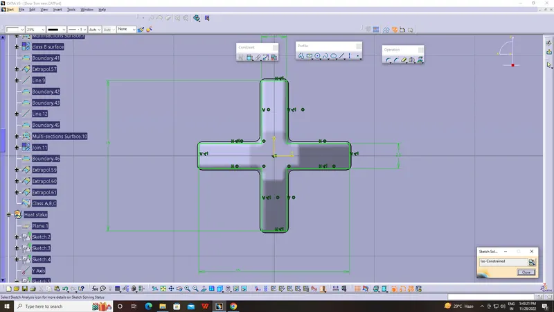
- Create chamfer of 3*45 degree on the to face for the easy entry of the locators to the holes.
- Draft angle 0.5 degree is given to all the faces.
- 0.5 mm edge fillets are given to all the edges.
- Finally, using union trim Boolean operation, trim the locators with the door trim body part.
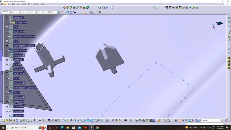
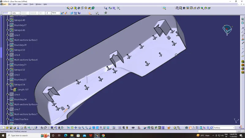
Final Door trim Body with the required engineering features:
DRAFT ANALYSIS
The Draft Analysis is a command enables you to detect if the part you drafted will be easily removed. This type of analysis is performed based on colour ranges identifying zones on the analysed element where the deviation from the draft direction at any point, corresponds to specified values.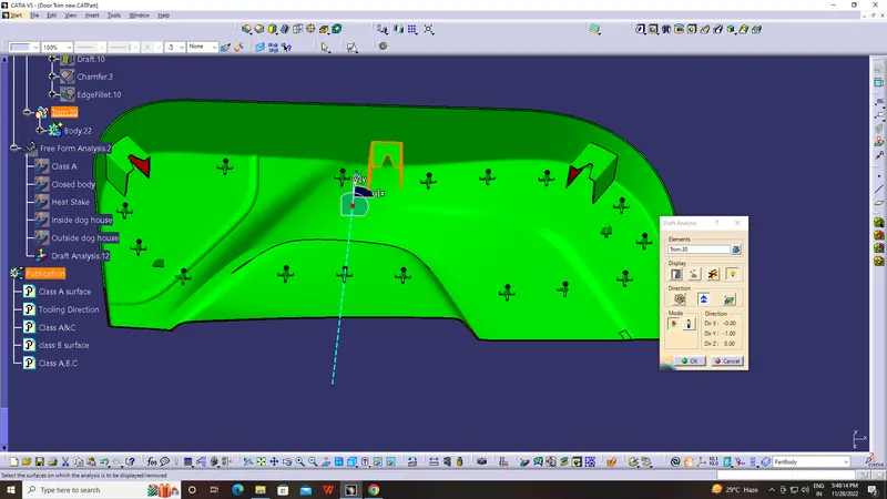
Conclusion
I have created class B and C surfaces using the given class A surface and created enginnering features on the B surface. Draft analysis is successfully performed on both CLASS A surface and Final component.