Week 11 - Final project
AIM- To design and development of vehicle interior door trim using given class A surface along with master section. Also create the side attachment features as per design rules.
OBJECTIVE-
- To create the thickened part using master section for reference.
- To Create the mounting features are per design rules in the industry and with master sections.
- To creating tooling axis and perform draft analysis.
INTRODUCTION-
The door panel is the interference between the interior of the car and the inner workings of the door. Generally, the door panel is divided into two parts of easy designing like arm rest, map pocket, lower substrate, bottle holder, these requires one of the toughest requirements among the interior parts of the car. This should be designed to with stand the load while being less than 2mm in the thickness and also protect the occupants during collisions. Door currently has an inner full width panel consisting of electronic windows. Central locking system and speakers. These panels typically consist of a covered with either textiles or plastics.
A surface:
A surface is the styling surface that is visible to the consumer and gives an aesthetic look for the model designed. Surfaces which are having curvature continuity is also called Class A Surface. Engineering features are not added to this surface. Class A is any of set freedom surface high efficiency and quality. Although strictly it is nothing more than surface have curvature and tangency alignment.
B Surface:
Class B surfaces are the secondary surfaces that you can see sometimes includes all the engineering features such as dog house, locators, ribs, flanges, etc. This
surface is the direct offset of the Class A surface which gives thickness to the component.
C Surface:
This surface is the combination of the Class A and Class B surfaces also they are the backside surfaces that can have tool marks, flash, and other imperfections without hurting appearance, function, etc.
INPUT OF CLASS A SURFACE
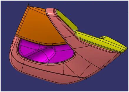
Since the input class A surface is containing four different parts(class A). So class b and c for all the surface has been created in separate catpart. Also performing draft analysis and tooling axis separately. finally all the surface have assembled together in one catproduct
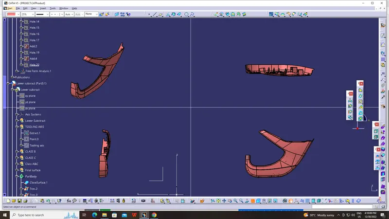
CREATION OF TOOLING AXIS – LOWER SUBSTRATE
DRAFT ANLAYSIS
Draft analysis in catia is a command that is used to detect if the part you drafted will be easily removed from the mold. it is performed based on color ranges identifying zones on the analyzed element.
Most of the industries is using minimum draft angle is 3 degree
PROCEDURE
- Check all the boundary whether it has connected or not.
- Check the model visually & choose the best tooling direction which should be easy for draft.
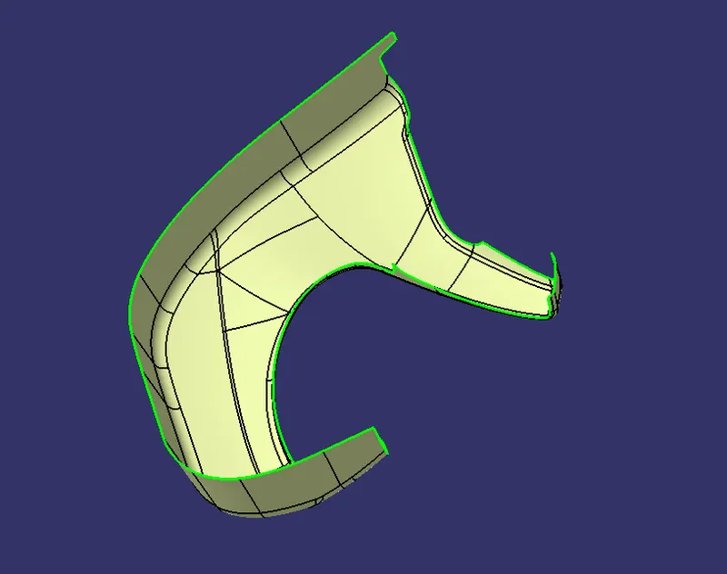
CREATING THE TOOLING AXIS
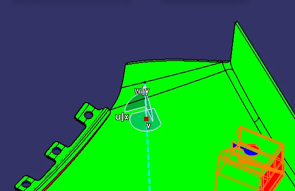
- Create a point on centre of gravity of part by using measure inertia command and insert a axis system on the point as shown below.
- create a point -direction line parallel to the y axis and named as TOOLING AXIS as shown below
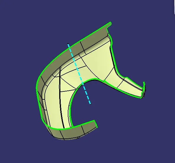
CREATION OF TOOLING AXIS – BOTTLE HOLDER
PROCEDURE
- Check all the boundary whether it has connected or not.
Check the model visually & choose the best tooling direction which should be easy for draft.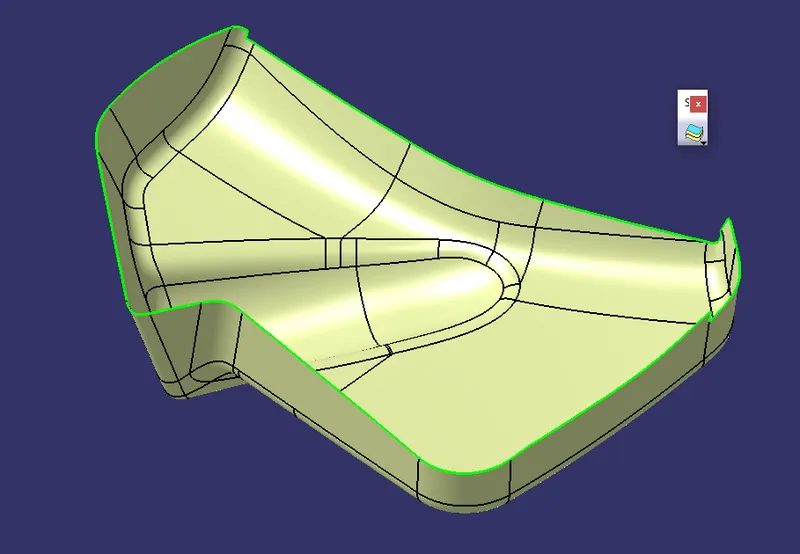
- After analyzing the above model,we have to create tooling axis on Y
CREATING THE TOOLING AXIS
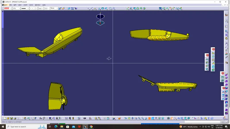
CREATION OF TOOLING AXIS – DOOR ARMREST
PROCEDURE
- Check all the boundary whether it has connected or not.
- Check the model visually & choose the best tooling direction which should be easy for draft.
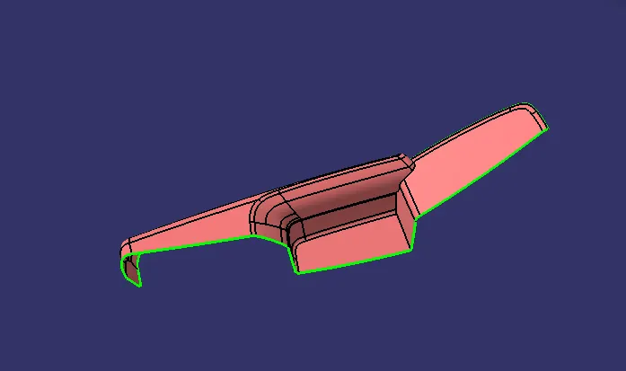
- After analyzing the above model, there is an chance for undercut when we consider tooling axis from z.so we have to create tooling axis on x,y and also z
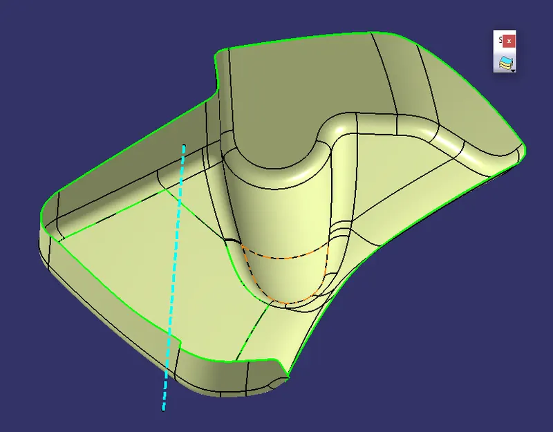
CREATING THE TOOLING AXIS
- Create a point and insert a axis system on the point 1 as shown below
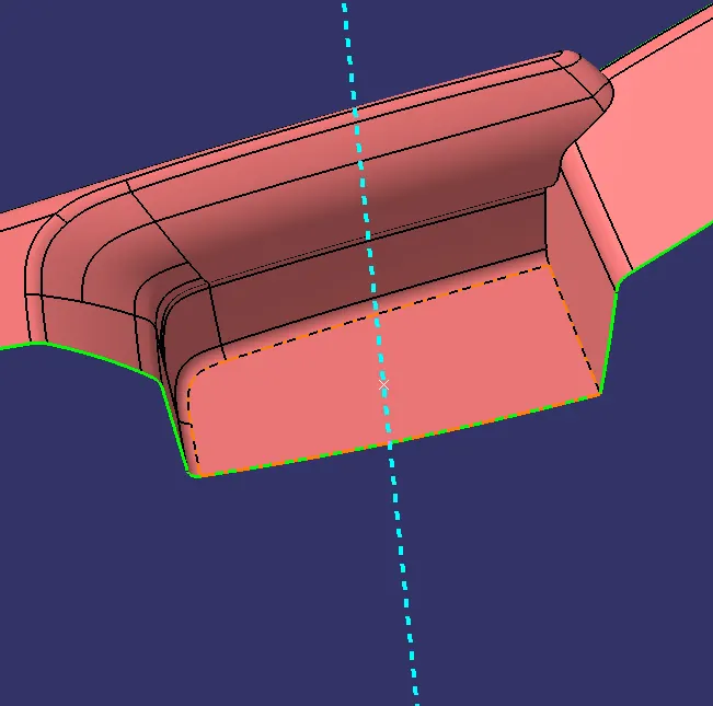
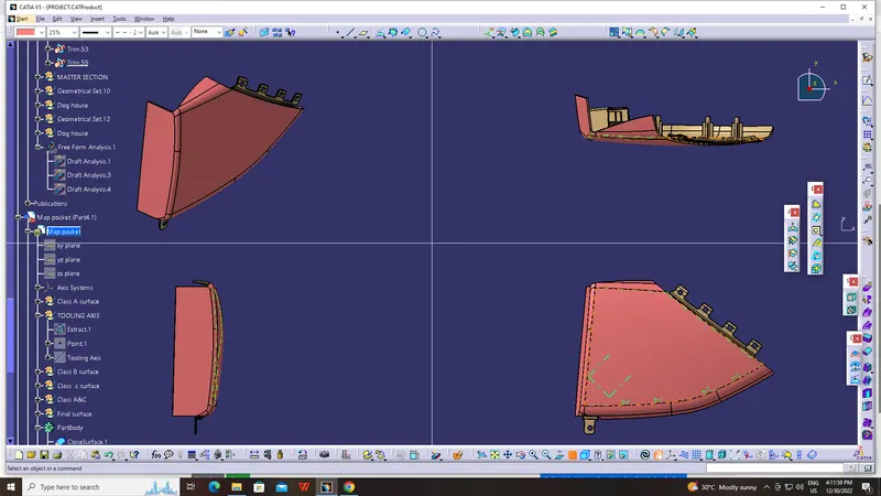
CREATION OF TOOLING AXIS –MAP POCKET
PROCEDURE
- Check all the boundary whether it has connected or not.
- Check the model visually & choose the best tooling direction which should be easy for draft.
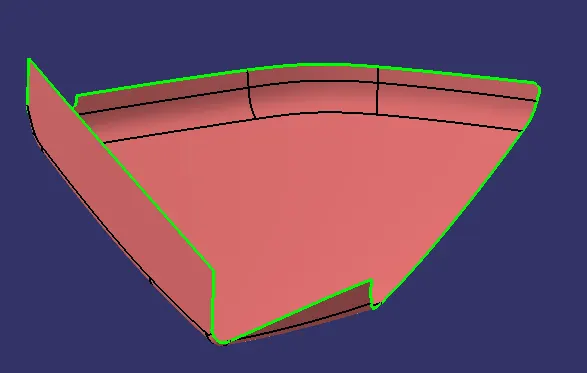
- After analyzing the above model the best tooling axis is y direction.
CREATING THE TOOLING AXIS
- Create a point on centre of gravity of part by using measure inertia command and insert a axis system on the point as shown below
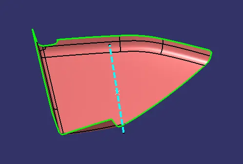
DRAFT ANALYSIS REPORT OF CLASS A – LOWER SUBSTRATE
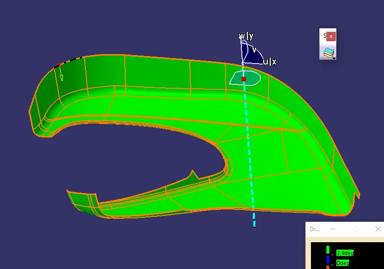
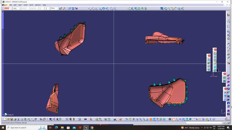
DRAFT ANALYSIS REPORT OF CLASS A – MAP POCKET BOTTLE HOLDER
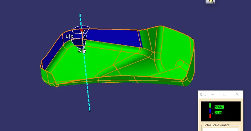
DRAFT ANALYSIS REPORT OF CLASS A – DOOR ARM REST
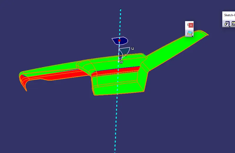
DRAFT ANALYSIS REPORT OF CLASS A – LOWER SUBSTRATE
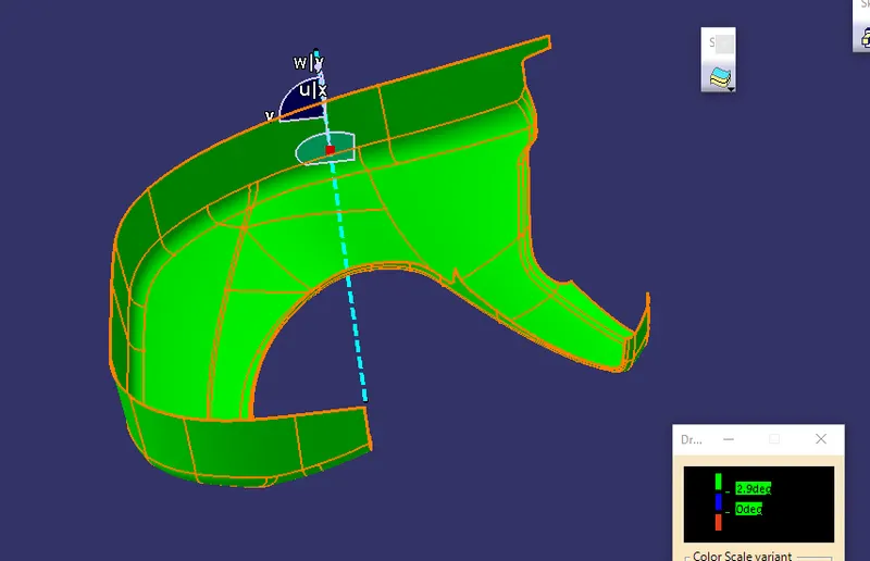
CREATION OF CLASS B SURFACE
- Insert a new gemeotrical set.Measure the value of thickness in master section.The value is 2.5mm
- Offset the class A surface to 2.5mm.
- Check all the sub elements are formed if not try to fix it locally
LOWER SUBSTRATE CLASS B
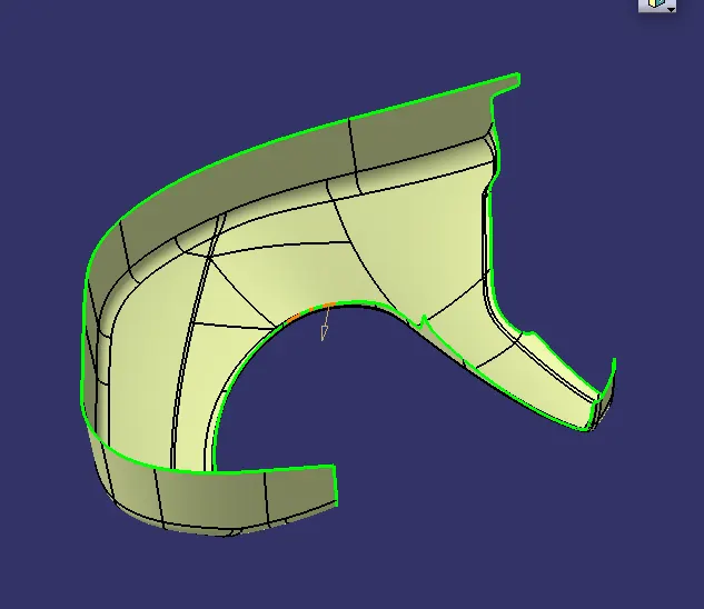
MAP POCKET WITH BOTTLE HOLDER CLASS B
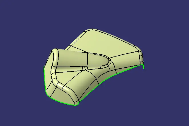
DOOR ARMREST CLASS B
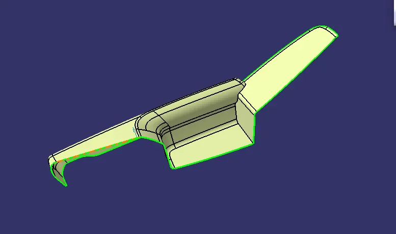
MAP POCKET CLASS B
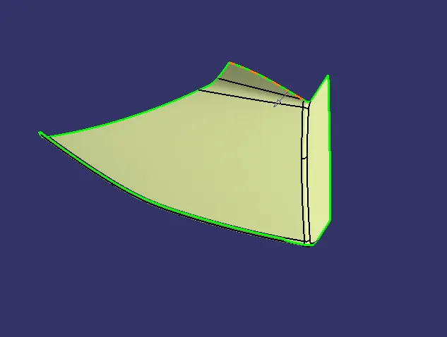
CREATION OF CLASS C SURFACE
- Analyse the class A once where the sweep is easier to create towards tooling direction
- Create a boundary using limitation points whereever possible for sweep
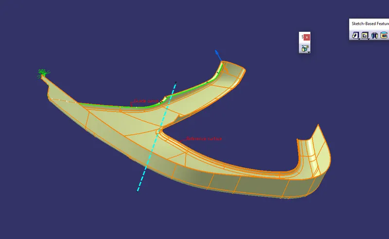
- Sweep the above boundaries for industrial standard 3 degree towrads tooling axis
- Now Create the c surface by using multisection solid where the sweep cant perform.
- Create a points on the curve as shown below and Create a line by using point to point line.
- Split the both surfaces by using split command
- Create a boundary by using on the class a surface that is going to pefrom multisection surface
- Join the surfaces by using multisection surface
- By using the same method creating the c surface whereever the sweep is not possible
- After ,join all the c surface
- Using the same method create c surfaces for all the parts
MAP POCKET WITH BOTTLE HOLDER CLASS C
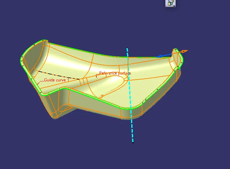
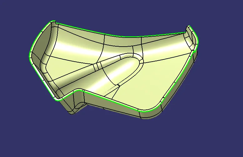
DOOR ARMREST CLASS C SURFACE
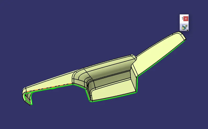
MAP POCKET CLASS C
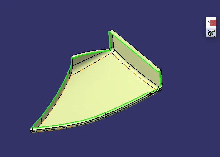
FINAL SURFACE
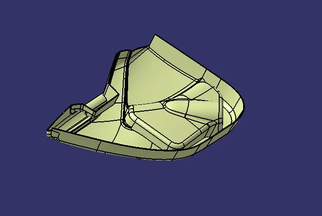
CREATION OF B SIDE ATTACHMENT FEATURES
DOG HOUSE
- The two main purposes of a dog house are to avoid sink marks and to house various other engineering features like screw boss, locators, push clips etc.
- In this case, the dog house is designed to house the push clips and the 4 way locator. The dog house designed for the push clip features a slot on the top face to accommodate the push clip
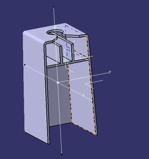
- Doghouse wall thickness at the intersection of the part wall (C) should be 40% or less than the main wall stock (T).
- The height of ( B ) should be between 3.0 – 6.0 mm
- Outer surface of dog house must have a draft angle of 3 degrees
- Inner surface of dog house must have a draft angle of 0.5 degrees
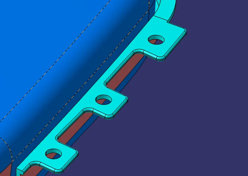
HEAT STAKE:
- Heat stakes are used in thermoplastics to assemble two parts together by locally heating and cooling the plastic and allowing it to reform itself and act as a joint for the two materials.
- We have placed 9 heat stakes in the model based on the reference points created by estimation.
- One of the important factor to be considered while designing the heat skates is the height of the heat skates. It should always be less than the height of the locators

DRAFT ANALYSIS ON PART:
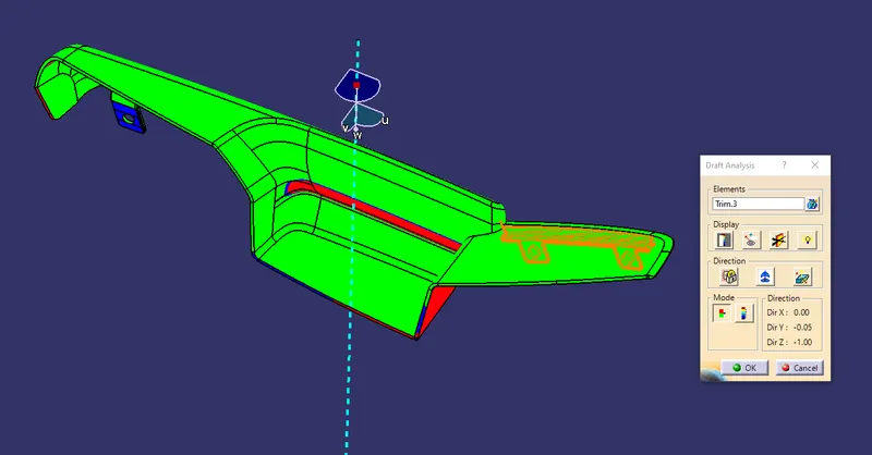
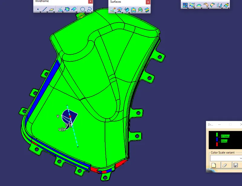
- Draft analysis is done on the final part with the tooling axis as reference
- Green surface indicates the areas where the draft is more than 0.5 degrees.
- Red surface indicates the areas having negative draft.
- All the engineering features are given a draft with reference to the tooling axis and hence they can be cleared in the main tooling
- Lifter axis for clearing the dog house inner surfaces are provided for each individual dog house
MODELS IN VARIOUS ORIENTATIONS
DOOR ARM REST