Week 9 - Attachment Feature Creation (Ribs & Screw Boss) - Challenge 1
Attachment Feature Creation (Ribs & Screw Boss)
AIM:
- To Create the Door Handle Component from the given Class-A surface.
- To Create the tooling axis for the given Class-A Surface meeting the requirements of the draft angle.
- To Attach B side Features in the component.
- To perform the Draft analysis on the model.
DESCRIPTION:
1. CREATING TOOLING AXIS
The Tooling Direction is basically the direction that the mold pulls a part. The mold is built in two separate pieces, basically. You have a Cavity side and you have the Core side. The Core pulls apart from the Cavity and that's the Dye line or the Tooling Direction.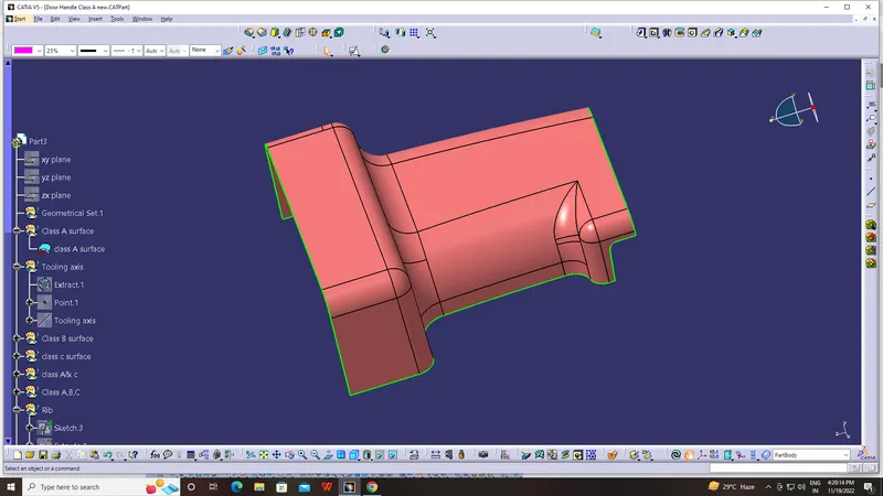
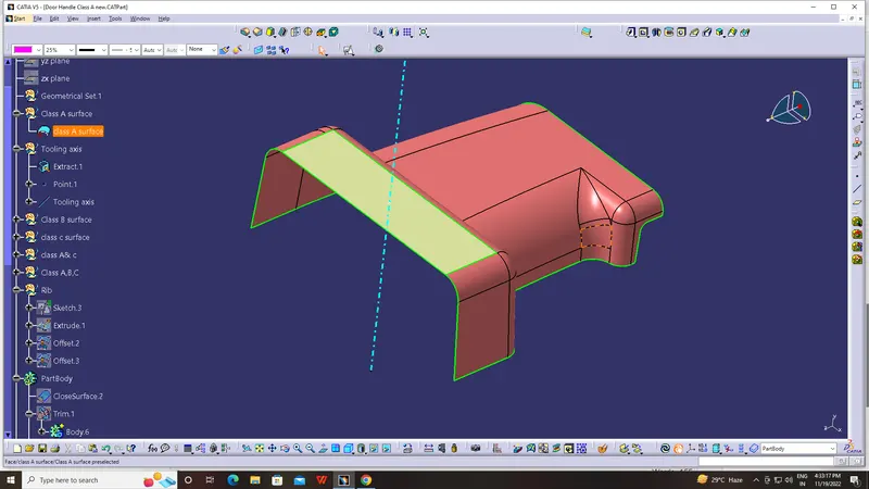
2. DRAFT ANALYSIS
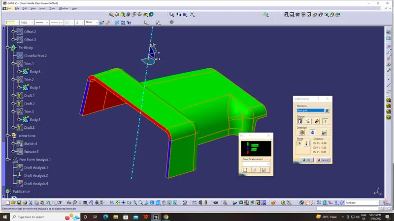
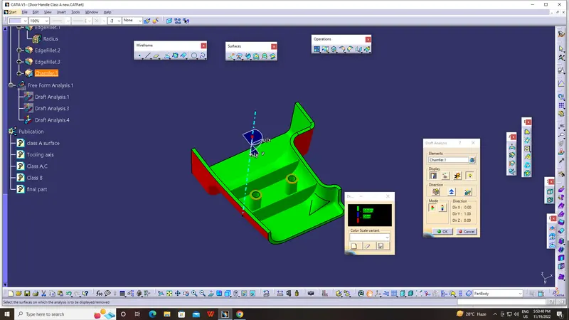
The Draft Analysis command enables you to detect if the part you drafted will be easily removed. This type of analysis is performed based on color ranges identifying zones on the analyzed element where the deviation from the draft direction at any point, corresponds to specified values.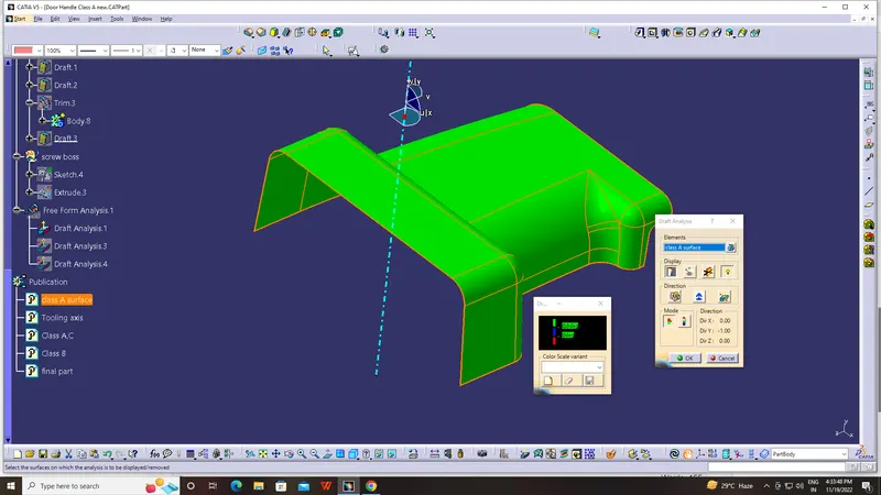
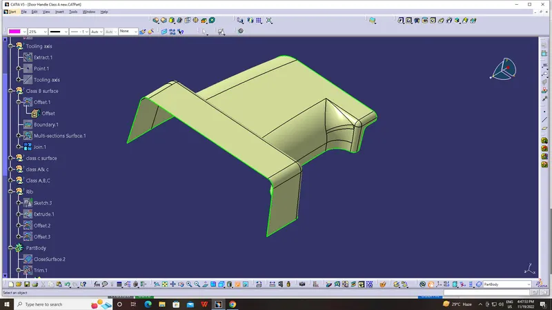
3. CREATING CLASS B SURFACE
Class-B surface means thickness of a part it is not visible and is inside part. In other words, Class-B surface is a surface below a certain thickness from the class-A surface. This is the surface that contains engineering aspects of a model.
- Offset the class-A surface to 2.5mm inward direction.
- Rework on the patches and discontinuity of the offset surfaces using the features like extract, multi-extract, sweep, multi-section surfaces, extrapolate.
- To ensure the continuity of the Class-B surfaces check the boundary command to find out the boundary.
- Hence class-B surface creation is done.
4. CREATING CLASS C SURFACE
- Extract the boundary from the class A surface using boundary command.
- Using disassemble tool to divide the boundary as the boundary contains domains.
- Use sweep command > choose profile type line > subtype as with draft direction > choose guide curve and draft direction > draft angle as 3 degree > preview.
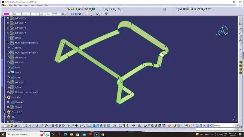
5. Joining of Class A & C:
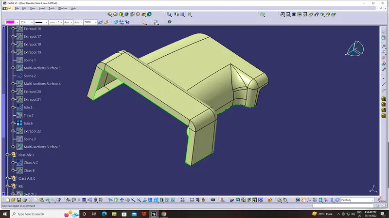
- After Joining of Class A & B then trim the output with class B surface to get final output.
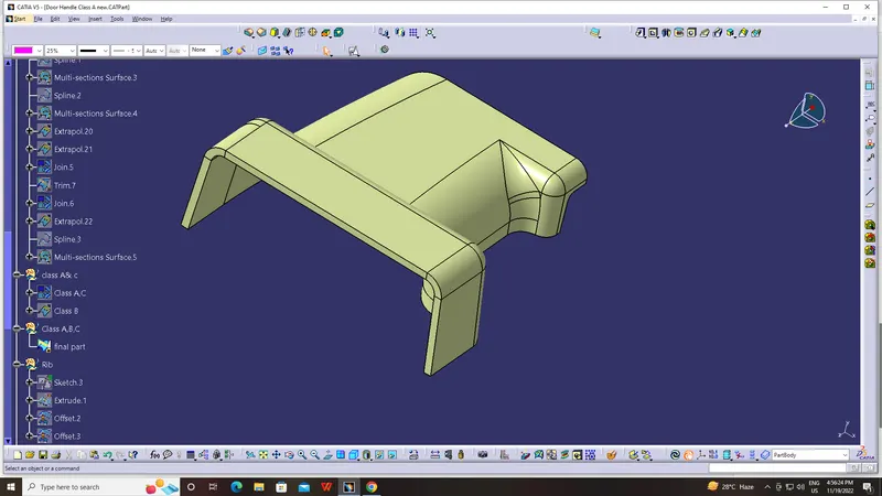
6.Draft Analysis:
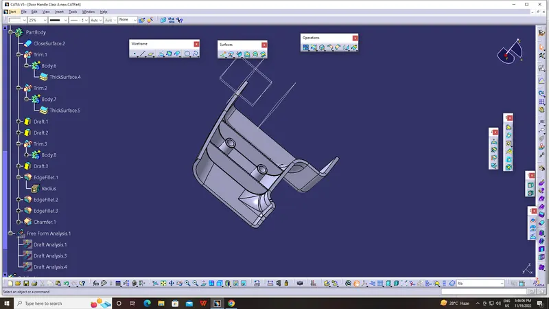
- Now open part design workbench and using close body surface create a solid of the component.
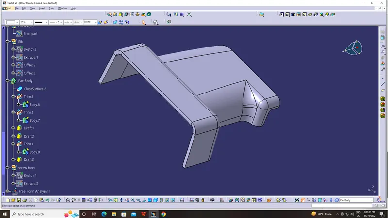
7. B SIDE FEATURES CREATION
RIB CREATION
- It used to provide the strength of the surface.
- Design Principle for Rib Creation
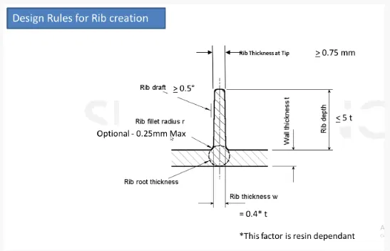
- Sketch Used For Rib Creation
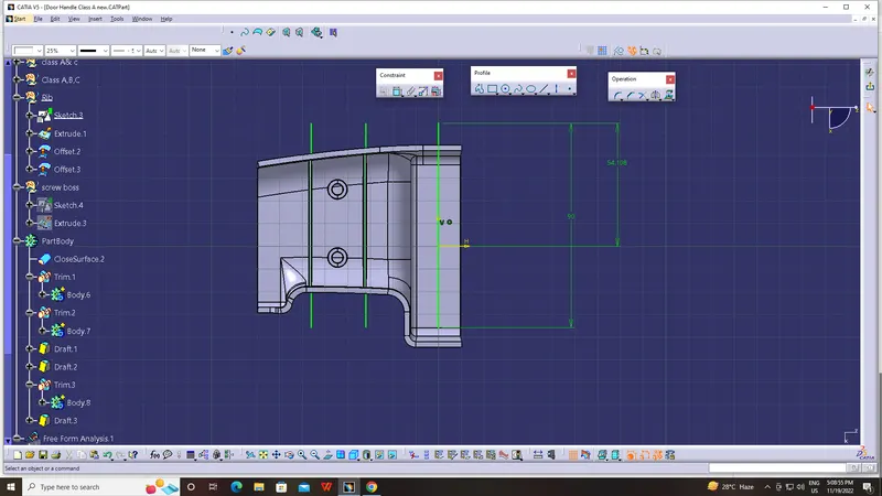
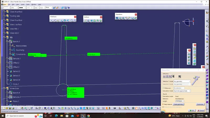
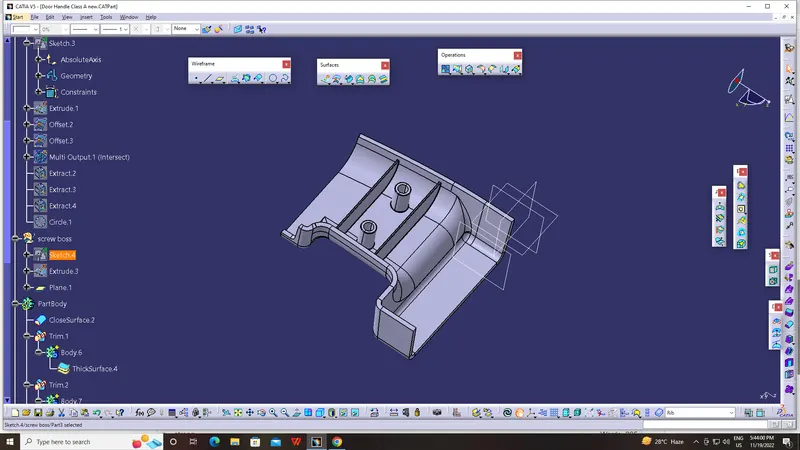
SCREW BOSS DESIGN
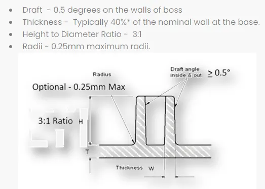
- Design Principle for Screw Boss Creation
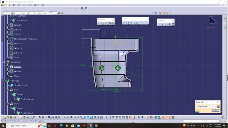
- Sketch Used For Screw Boss Creation
8. END DRAFT ANALYSIS
CONCLUSION:
- The Tooling axis and the SolidCAT part with B Side Features is created from the given Class A Surface and Draft Analysis is Performed.