Week 8 - Challenge 3 - Coin Holder Design
Aim -
Create the Coin Holder Plastic component through the given Class-A surface. To begin with, the tooling axis for the given Class-A Surface should be created meeting the requirements of the draft angle and at the end perform the Draft analysis on the model.
objectives :
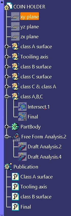
- To ensure proper tree structure is followed
- To keep the design as per requirement
- All the sketches should be iso constrained
- To publish the Class A,B and C Surface.
Raw Material Used in Coin Holder:
Acrylonitrile butadiene styrene(ABS)
- Based on the application we consider thermo plastics on that type of part.
- Aesthetically - superior finishes.
- Remolding / Reshaping capabilities.
- Highly recyclable.
Design procedure:
- Checking Class A input for imperfections.
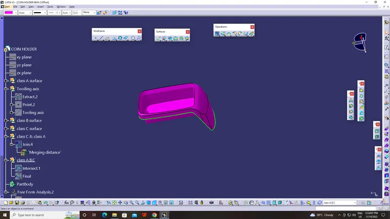
The input Class A surface is checked for discontinuities and joined together to get a complete Class A surface as one.
TOOLING AXIS CREATION:
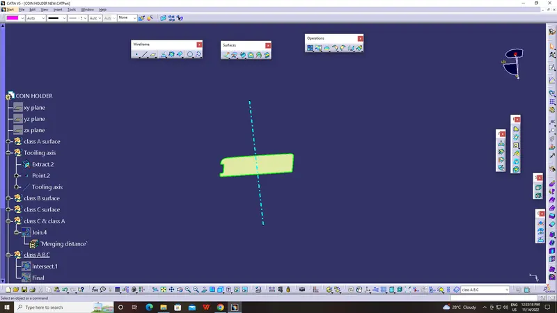
- Generally tooling axis is created using bisecting line method. But in the components where it has a bin, then the tooling axis is considered as a line normal to the base surface of the bin. The same is done with this component. A line normal to the base surface is created and considered as a tooling axis.
Draft analysis of Class A:
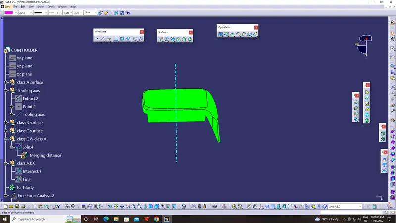
- Draft analysis is performed on Class A to check the validity of the tooling axis. During draft analysis, it was observed that bin walls are having a 90-degree angle with the base. There is no minimum draft given to the walls. Since we are not authorized to make changes to the Class A surface, we can inform the Class A designer to give the minimum draft to the walls.
CLASS B SURFACE CREATION:
- As usual B surface is created using the standard procedure by extract, un trim, extrapolate and offset commands. B surface of this coin holder is divided into a base, side walls, top wall, and outer surface. B surfaces of all these sub-parts are created and trimmed together to join as a single surface.
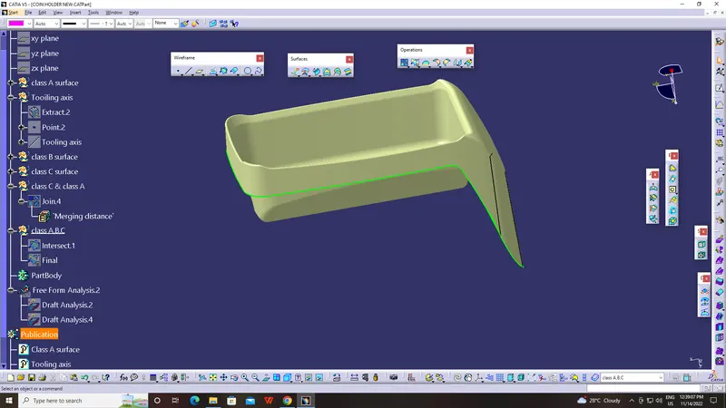
The offset distance is kept at 2.5mm as the component thickness is 2.5mm.
CLASS C SURFACE CREATION:
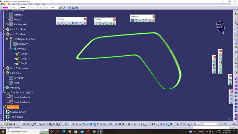
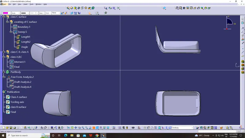
- Class C surface for this component is created using the sweep command. All the ends of the component surface were facing downwards, so the C surface will create perpendicular to the B surface.
- To create a C surface boundary of Class A surface and surfaces adjacent to the boundary are extracted. Then sweep with reference surface commands is used and the surface is created at 90 degrees.
Creating final closed volume, converting in solid body and draft analysis:
- Once all surfaces are created Class A, B, and C surfaces are joined together to get the final closed volume. The closed volume is then converted into a solid body using the closed volume command in the part design workbench.
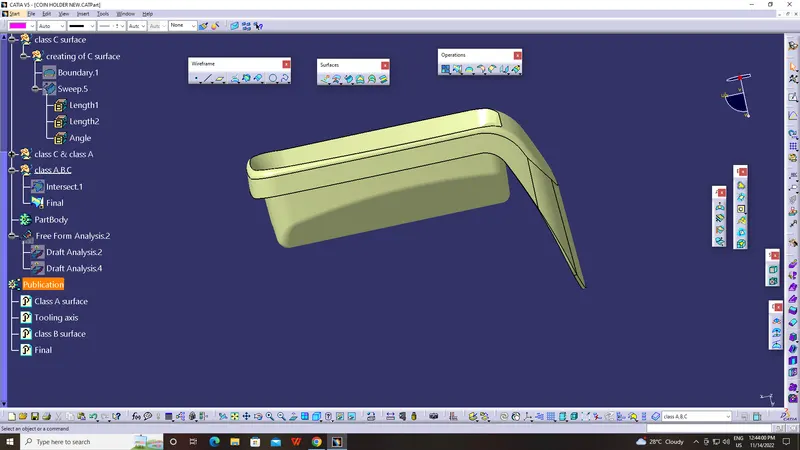
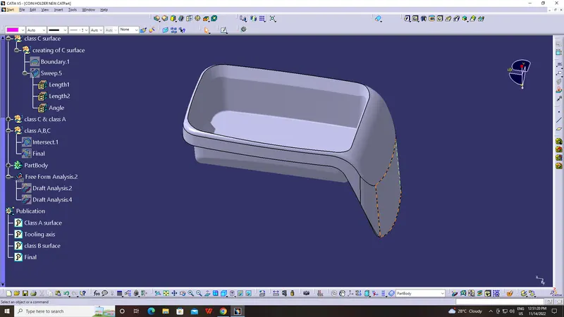
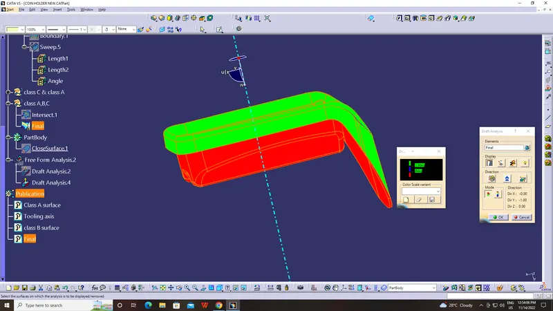
- Draft analysis is done on the final component to check manufacturing ability. The walls of the bin are having zero draft angle with the tooling axis. This will be ignored since it is given on the Class A surface.
Tree structure: