


Project 1
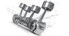
WIRING HARNESS DESIGN AIMDesign and develop the Wiring harness on Given V6 Engine and Prepare flatten view drawing in CATIA V5. Application of all Packaging rules, Industry best practices studied in this course shall be demonstrated in design.INTRODUCTIONA wire harness, also commonly referred to as a wiring harness,…
Daison Vimalraj
updated on 28 Feb 2023

Project Details
Leave a comment
Thanks for choosing to leave a comment. Please keep in mind that all the comments are moderated as per our comment policy, and your email will not be published for privacy reasons. Please leave a personal & meaningful conversation.
Other comments...
Be the first to add a comment
Read more Projects by Daison Vimalraj (29)
Week 4 Challenge
ABOUT LENS Lens is an optical material that controls the light emitted from a light source and allows it to distribute in a certain angle and density. Lenses provide precision control over light angle. Lenses can be made of plastic, silicon or glass material in various shapes and sizes. …

29 Mar 2023 06:03 AM IST
Week 3 Challenge
ABOUT LENS Lens is an optical material that controls the light emitted from a light source and allows it to distribute in a certain angle and density. Lenses provide precision control over light angle. Lenses can be made of plastic, silicon or glass material in various shapes and sizes. …
29 Mar 2023 05:48 AM IST
Project 2
Aim: Route the Wiring Harness on given Car body and prepare flatten view drawing in Catia V5 Objective: The objective of this project is to route the wiring harness and prepare flatten view drawing for the tailgate of the car. All types of packaging rules have to be considered while routing the harness and industry based…
01 Mar 2023 11:28 AM IST
Project 1
WIRING HARNESS DESIGN AIMDesign and develop the Wiring harness on Given V6 Engine and Prepare flatten view drawing in CATIA V5. Application of all Packaging rules, Industry best practices studied in this course shall be demonstrated in design.INTRODUCTIONA wire harness, also commonly referred to as a wiring harness,…
28 Feb 2023 11:05 AM IST
Wiring harness design in CATIA V5 - 3D modeling Week 7 Challenge
AIM: TO FLATTEN THE WIRING HARNESS AND DRAFT THE WIRING HARNESS ASSEMBLY. GIVEN: HARNESS ASSEMBLY: HARNESS FLATTENING: WE GO TO THE HARNESS FLATTENING WORKBENCH AND DEFINE THE FLATTENING PARAMETERS. WE USE THE EXTRACT COMMAND TO BRING THE HARNESS ASSEMBLY TO THE FLATTENING WORKBENCH HERE. CHOOSING A SUITABLE PLANE WE FLATTEN…
10 Feb 2023 09:53 AM IST
Wiring harness design in CATIA V5 - 3D modeling Week 5 & 6 Challenge
Aim: Route two electrical harnesses per the given layout and interconnect them as a single harness assembly check for bundle continuity, and bundle warnings, and then provide annotations for the final harness assembly. Objective: The objective of this project is to first route the two Harness A and Harness B as per the…
08 Feb 2023 08:00 AM IST
Design of backdoor
AIM: To design the back door of the car and make the inner panel for the back door and also design the necessary re-enforcements. INTRODUCTION: The trunk (North American English) or boot (British English) of a car is the vehicle's main storage or cargo compartment, often a hatch at the rear of the vehicle. It is also…
06 Feb 2023 05:46 AM IST
Wiring harness design in CATIA V5 - 3D modeling Week 4 Challenge
Aim: 1) To Route the following harness layout in the Electrical workbench. 2) Add protective covering on all branches connected to DT06-2S & DT06-4S connectors. Given: CAD data of the following Connectors: DT06-4S DT06-6S DT06-2S DT06-08SA Connectors Layout Design: Steps to be followed: 1. Download connector 3D data…
01 Feb 2023 02:25 PM IST
Wiring harness routing & packaging Rules Week 3 Challenge
Q1). The given clip was downloaded and opened as a part file. I have to define two points that will be used as entry and exit points. Then a plane has to be defined at the points. A base plane has to be defined at a distance of 2 to 3 mm from the clip. again we define the exit point at the first definition as the…
31 Jan 2023 09:37 AM IST
Wiring harness design in CATIA V5 - 3D modeling Week 2 Challenge
AIM- Define given connectors & connector clip as an Electrical Connector and add their necessary properties using Electrical Part design workbench in CATIA V5 OBJECTIVE- The objective of this project is to first, download the given files from TE.com then define them as an electrical connector…
30 Jan 2023 02:27 PM IST
Roof Design
AIM: To a given roof styling, create essential flanges and reinforcements. INTRODUCTION An automobile roof or car top is the portion of an automobile that sits above the passenger compartment, protecting the vehicle occupants from sun, wind, rain, and other external elements. …
23 Jan 2023 12:23 PM IST
Fender Design
FENDER DESIGN AIM: To design a front fender of a car by following the given master section as per the design considerations of OEM. FENDER It is an aesthetic component/part of a car that frames the wheels. Prevention of sand, mud particles, and other road contaminants from being thrown into the engine…
09 Jan 2023 01:57 PM IST
Fender Design - Wheel Arch Challenge
Fender design-Wheel Arch Challenge Objective: To calculate the wheel arch area of the given fender and prove whether the car will pass the European Standards or not. Introduction: Wheel Arch is the shaped part of the bodywork of a car or other vehicle that allows the wheel to be accessed, and in the case…
05 Jan 2023 11:32 AM IST
Section Modulus calculation and optimization
Section Modulus Calculation Of Hood Aim To calculate the section modulus of the previously designed hood for analyzing its strength and also optimizing the design to see the difference in the bending strength of the hood. Higher the section modulus of a structure, the more the resistive it becomes to bending.…
04 Jan 2023 01:02 PM IST
Hood design-Week 2
Hood Design Flow chart of HOOD ASSEMBLY Objective Design hood outer panel, inner panel and reinforcements with the given outer hood skin, master section and design parameters. Introduction The hood or bonnet is the hinged cover over the engine of motor vehicles. Hoods can open to allow access to the engine compartment…
03 Jan 2023 02:08 PM IST
Week 11 - Final project
AIM- To design and development of vehicle interior door trim using given class A surface along with master section. Also create the side attachment features as per design rules. OBJECTIVE- To create the thickened part using master section for reference. To Create the mounting features are per design rules in…
30 Dec 2022 10:49 AM IST
Underbody Coating
Under-Body Coating: Underbody coating is usually a dense cladding (often based on rubber) applied uniformly to the undercarriage of the automobile. It is normally sprayed or painted on when the car is just out of the dealership and is clean. But even if you are getting the undercoating applied after a couple of years,…
27 Dec 2022 12:08 PM IST
Benchmarking
AIM: DETAILED REPORT ON BENCHMARKING To prepare a report explaining what is Bench-marking , Compare at least 4 Vehicles and Provide a Preoper conclusion for the report ,suggesting a suitable vehicle among the comparison made. WHAT IS BENCHMARKING ? It is the process of comparing one's business process and performance…
27 Dec 2022 08:03 AM IST
Week 14 challenge
Objective:- To assemble the different componenets of butterfly valve and applying GD&T rules using Catia V5 Assembly of Butterfly Valve:- GD&T Assembly Detailed Report of each component Types and Application of Butterfly Valve Introduction A butterfly valve is a quarter-turn valve that initiates…
27 Dec 2022 07:15 AM IST
Week 9 - Project - A pillar Design with Master Section
Week 9 - Project - A pillar Design with Master Section OBJECTIVES: To create the class B and class C surfaces from the given class A surface To form a solid geometry by combining all the surfaces To create a dog house for the solid part whilst following the design rules To perform draft analysis on the class A surface…
01 Dec 2022 09:23 AM IST
Week 9 - Project 1 - Door Trim Lower with Engineering Features
AIM This Report aim is to perform draft analysis for the given surface by defining a tooling direction appropriate to the shape of the surface and also to create the class-B,class-C surfaces and final closed body with the help of given Class A surface of Door trim lower and to create heat stakes and 4 way loactors…
28 Nov 2022 12:20 PM IST
Week 9 - Attachment Feature Creation - Challenge 2
Dog house design for the Door Trim: Aim: Create the Dog House for the Door Trim considering the design rules and perform the draft analysis for class A and create the final close body component and perform the draft analysis. Objective: Create the Tooling axis Design the class-B and class-C surfaces and join them. Use…
24 Nov 2022 07:23 AM IST
Week 9 - Attachment Feature Creation (Ribs & Screw Boss) - Challenge 1
Attachment Feature Creation (Ribs & Screw Boss) AIM: To Create the Door Handle Component from the given Class-A surface. To Create the tooling axis for the given Class-A Surface meeting the requirements of the draft angle. To Attach B side Features in the component. To perform the Draft analysis on the model. …
19 Nov 2022 12:31 PM IST
Week 8 - Challenge 6 - Core & Cavity Design
AIM:To create a switch bezel from the given A-class surface by considering a thickness of 2.5 mm and also creating Core and Cavity blocks for it. A class surface : The input of the product designer is in the form of the A-class surface. The job of the product designer is to create the B and C surfaces keeping all the aspects…
17 Nov 2022 02:57 PM IST
Week 8 - Challenge 4 - Bumper
BUMPER DESIGN AIM Create the Bumper Plastic component through the given Class-A surface. To begin with, the tooling axis for the given Class-A Surface should be created meeting the requirements of the draft angle and at the end perform the Draft analysis on the model. INTRODUCTION A bumper is a structure attached to or…
15 Nov 2022 10:36 AM IST
Week 8 - Challenge 3 - Coin Holder Design
Aim - Create the Coin Holder Plastic component through the given Class-A surface. To begin with, the tooling axis for the given Class-A Surface should be created meeting the requirements of the draft angle and at the end perform the Draft analysis on the model. objectives : To ensure proper tree structure…
14 Nov 2022 10:52 AM IST
Week 8 - Challenge 2 - Switch Bezel Design
OBJECTIVE:- The objective of the project is to design the switch bezel and to do a draft analysis for it by creating the required tooling direction with the help of Bisecting method. RAW MATERIAL USED IN SWITCH BEZEL:- ABS (Acrylonitrile Butadiene Styrene) INTRODUCTION:- The control panel bezel is the frame part of the…
08 Nov 2022 06:36 AM IST
Week 8 - Challenge 1 - Base Bracket Design
Aim :- To design the Base Bracket plastic component through the given Class-A surface. Raw material used in Base bracket of plastic component: Thermoset plastics DESIGN PROCEDURE: To setup the class-A surface and to creating a tooling axis add draft angle To create a base surface…
07 Nov 2022 11:37 AM IST
Week 10- Assembly Workbench
27 Oct 2022 07:04 AM IST