Week 3 Challenge
ABOUT LENS
- Lens is an optical material that controls the light emitted from a light source and allows it to distribute in a certain angle and density.
- Lenses provide precision control over light angle.
- Lenses can be made of plastic, silicon or glass material in various shapes and sizes.
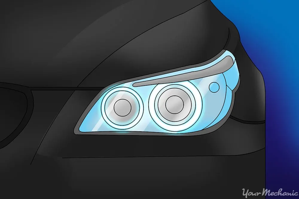
MATERIAL USED FOR LENS LIGHTING
polycarbonates
WHY PC(polycarbonates)
- COST EFFECTIVE
- LOW MELTING POINT
- HIGH IMPACT STRENGTH
- GOOD SURFACE FINISH
- TRANSPARENT
COMPARISION OF MATERIAL TO CHOOSE FOR LIGHTING LENS
Polycarbonate vs ABS |
|
| Polycarbonate is an amorphous polymer made by melt polycondensation of bisphenol A and diphenyl carbonate. | ABS is a thermoplastic resins made by blending three types of monomers: acrylonitrile, butadiene, and styrene. |
| Properties | |
| Polycarbonate has excellent creep resistance, very good dimensional stability, good electrical characteristics, self-extinguishing properties, excellent impact, and flexural properties. | ABS has impact resistance, good processability, good mechanical properties, high heat distortion temperature, and gloss property. |
| Applications | |
| Polycarbonate is used for the manufacture of lenses, windshields, containers, light fittings, compact discs (CD), pump impellers, helmets, small, appliances and trays. | ABS is used for the manufacture of piping and fittings, instrument and appliance housings, components of office automation equipment, inner door cabinets of refrigerators, bathtubs, and door covers. |
| Hardness and Flexibility | |
| Polycarbonate is extremely hard, brittle and not flexible. | ABS is hard and flexible due to rubbery part. |
| Processability | |
| Polycarbonates require high temperatures to process, so their processability is low. | ABS has good processability. |
MANUFACTURING MACHING FOR LENS LIGHT
INJECTION MOLDING MACHINE
TOOLING AXIS
- The direction in which the mold or core and cavity opens is the tooling axis.
Steps Followed:
- Tooling Axis creation.
- Checking Draft analysis for created tooling Axis.
- Creating parting Surface.
- Creating Core Side.
- Creating cavity side.
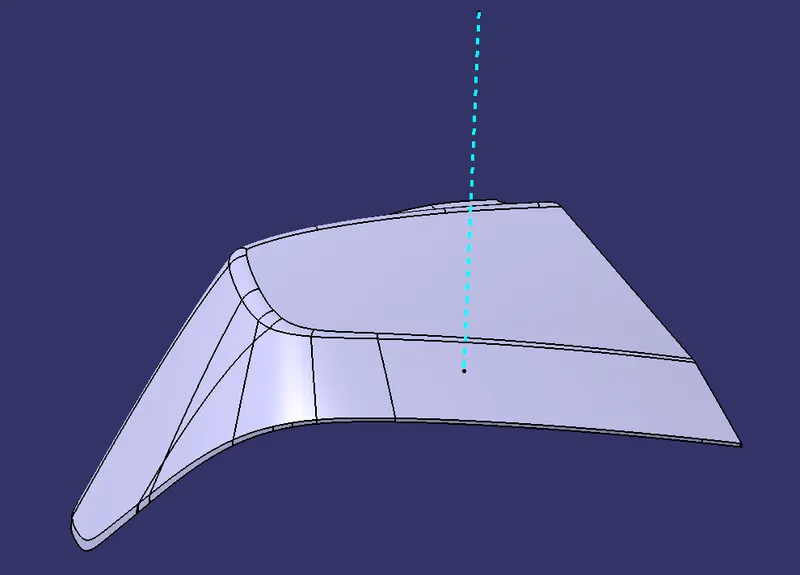
CLASS A SURFACE
- Class-A (or 'Strak') is a term used in specifically in automotive design.
- It describes the final production surface data for the aesthetic parts of the car.
- The term 'Class A' is often misunderstood, but it's generally seen as the 'Holy Grail' of surface modeling.
- Class A surface is used to show to the customer visulization,and it is a aesthetic surface.
CLASS B SURFACE
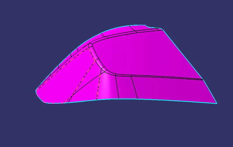
- The Class B finish is a quality finish with only minimal imperfections.
- A Class B finish is the most common finish for exterior surfaces.
- It is normally specified on surfaces such as external covers, panels, and parts that are fairly prominent.
- It is a offset surface of A,Which the surface were can not able to see Over the customer.
CLASS C SURFACE
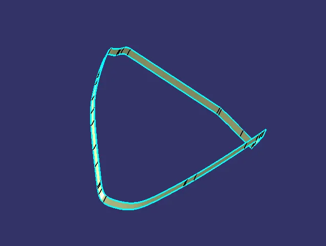
- The Class C finish allows more imperfections than Class A or B.
- Class C is often specified for interior surfaces not readily visible, surfaces that will be covered by another part when assembled, or surfaces which the Customer feels do not need to meet a high cosmetic finish.
DRAFT ANALYSIS
- The draft analysis technique is used to analyze whether our part model created in CAD is manufacturable based on the draft condition applied.
- Here the part should get easily removed from the panel dies .
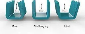
DRAFT ANALYSIS OF CLASS A LENS
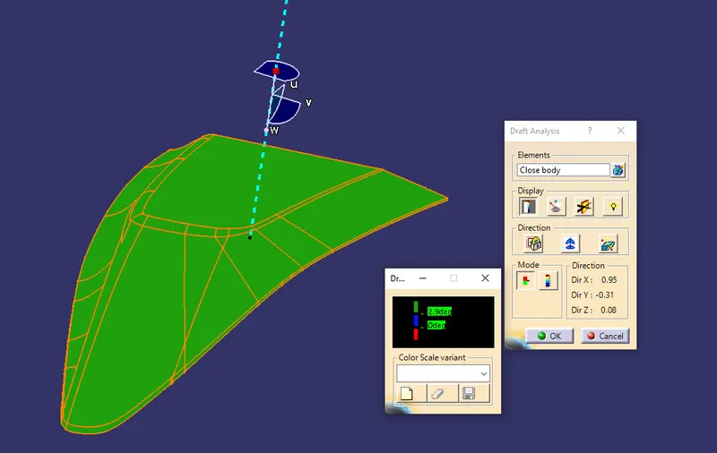
DRAFT ANALYSIS OF FINAL COMPONENT OF LENS