Week-7 Challenge: DC Motor Control
1.A. To Explain the MATLAB model for Speed control of a DC motor using BJT H-bridge
The Bipolar Junction Transistor:
The Bipolar Junction Transistor or BJT is three terminal semiconducting device. The terminals of BJT are Base, Collector, Emitter. When a forward voltage (Vf) is applied between collector and emitter BJT operates in the saturated region. BJT used for power switching applications, operates as an IGBT. IGBT block can be used to model the BJT device.
Simulink model:
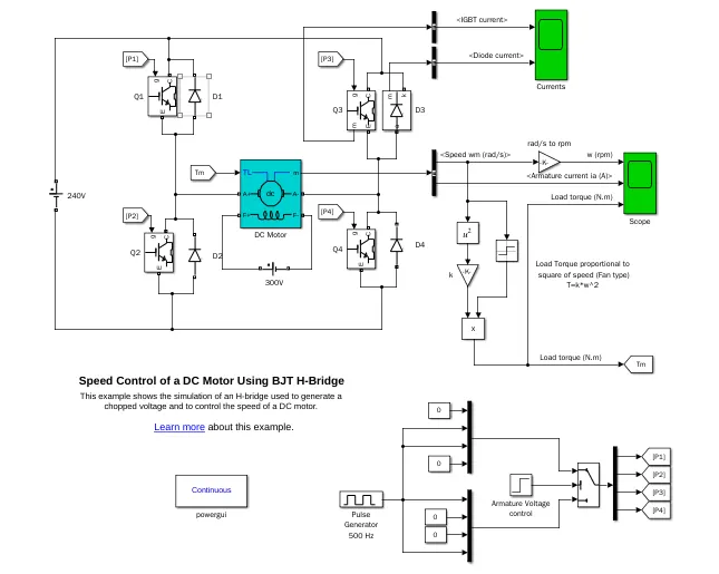
The IGBT block does not simulate the gate current controlling the BJT or IGBT. The switch is controlled by a Simulink signal. The DC motor in the given H bridge model has the capacity of 5 HP, Armature voltage 240V, Rated speed 1750 rpm. It can be simulates a fan type application where Load torque is proportional to square speed. The armature mean voltage can be varied from 0 to 240 V and the duty cycle can be varied from 0 to 100%.
Operation:
The H-bridge model consists of four BJT/Diode pairs (BJT simulated by IGBT models). One transistors pairs can be switched at a time : Q1 and Q4 or Q2 and Q3.
When Q1 and Q4 are closed, positive voltage is applied to the motor and diodes D2, D3 operate as free-wheeling diodes when QI and Q4 are switched OFF.
When Q2 and Q3 are closed, negative voltage is applied to the motor and diodes D1,D4 operate as free-wheeling diodes when Q2 and Q3 are switched off.
Using the default value of armature mean voltage (0 to 240 V), step time 0.5, duty cycle (specified in the pulse generator block is 75%), forward voltage (1v) and resistance (0.001 ohms) of four BJT diode pairs.
Output:
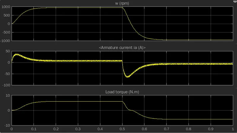
The result obtained from the plot of BJT H-bridge shows that sudden raise of armature current at the beginning, decreases a period of time and reaches a steady state. There is a sudden fall of armature current at step time of 0.5 seconds, increses for a period of time and reaches a steady state.
1.B. To explain the armature current shoot-up
Changing the Duty cycle of the pulse generator results in changes in the Gate signal of the switch which results in variation in the armature current.
Duty cycle of the Pulse generator is changed to 50% and keeping the remaining parameters as default, BJT H-bridge model is simulated and changes in the armature current shoot up need to be observed.
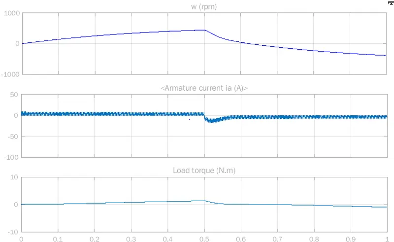
The result obtained for armature current plot represents constant armature current up to 0.5 second and after 0.5 seconds there is a drop in armature current. The Armature current drop increses slightly and becomes steady.
1.C. To Compare model DC7 chopper with H-bridge model
DC 7 Drive:
DC 7 Four Quadrant Chopper:
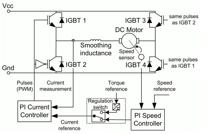
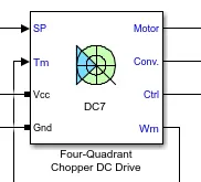
The Four-Quadrant Chopper DC Drive (DC7) block can operate in forward motoring, reverse motoring, forward regeneration and reverse regeneration. It consists of Four IGBT for switching operations. PI speed controller is used to control the speed of the motor by comparing the reference speed and motor speed. PI Current controller is used to change the current limit of IGBT using PWM pulses. The PI controller calculates the IGBT current limit using the current reference and the Motor current. The PI current controller and PI speed controller forms a closed loop control in the four quadrant operation of DC drive.
The advantage of DC 7 drive is that it can operate in all four quadrants. The Increase in switching frequency helps to reduce the armature current ripples. IGBT has higher switching frequency compared to thyristors. Increase in switching circuits also increases the complexity of the circuits.
Comparison of DC7 Drive chopper with H-bridge model:
* H-bridge model is similar to a open loop model as there is no feedback from the motor. Where as in DC 7 Drive forms a closed loop control using the speed feedback from the motor (The speed feedback can obtained by speed sensor or a Tacho generator).
* In H-bridge model the gate pulse for the switch is produced using Pulse generator which remains produces constant pulse sequence. In DC 7 Drive the pulse width is controlled by a PI current controller which varies depending on the Quadrant of operation and requirements.
* In H-bridge, required speed of motor cannot be obtained. In DC 7 drive required speed can be obtained.
* The H-bridge motor current is not used for feedback. In DC 7 drive PI current controllers are used to limit the IGBT current based on the reference current (to control the speed) and motor current.
* In H-bridge the armature current shoot up occurs. In DC 7 drive armature current shoot up is limited by the Smoothing Inductance and the PI current controller.
* In H-bridge the regenerative braking is limited. In DC 7 drive, with the help of four Quadrant operation operating efficiency is high with speed changing applications.
* The complexity of H-bridge is low compared to the DC7 drive.
2. To explain Two Quadrant Chopper operation
Two Quadrant Chopper:
In two Quadrant Chopper, the average voltage will be always positive but the average load current might be positive or negative. The two Switches CHI and CH2 should not be turned on simultaneously as the combined action may cause a short circuit in supply lines. For regenerative braking and motoring below chopper configuration is used.
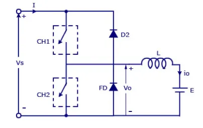
The output voltage Vo will be positive as the freewheeling diode FD is present across the load. When the chopper CH1 is ON the current flows from source to load. The inductor stores energy. When CH1 turned OFF the free wheeling diode FD starts conducting and the output voltage vo will be equal to V. The direction of the load current I0 will flow in the opposite direction. The current is will be flowing towards the source. The load current will be negative when the CH2 is ON. The current completes its path through diode D2.
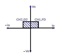
The Quadrant 1 and Quadrant 2 represents the forward motoring and reverse motoring of drive.
Regeneration cannot be done in the two Quadrant operation.
In Forward motoring mode, chopper 1 and the free wheeling diode will be in conduction.
In reverse motoring mode, chopper 2 and the Diode D2 will be in conduction.
Simulink model:
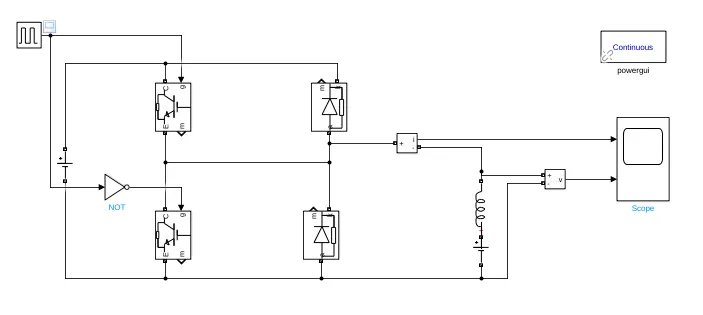
The Simulink model for the two quadrant chopper is constructed using two IGBT for switching and two Diodes for free wheeling. A pulse generator is used to provide the triggering signal to the switches. A NOT gate is used to invert the switching signal so that only one switch can be turned ON at a time. An Inductor and a Battery are used to instead of motor load. Voltage measuring and Current measuring blocks are used to view the current flowing through inductor and voltage across the inductor.
Pulse Generator:
Changing the Time period to 0.1 and pulse width to 50%, the two Quadrant model is simulated.
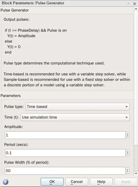
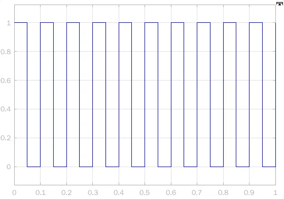
The corresponding output is obtained from the pulse width for the given input parameters in the pulse generator. The obtained waveform is the triggering signal to the IGBT 1 and also this waveform is inverted and used as a triggering signal to the IGBT 2.
Output:
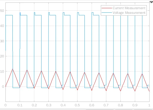
From the above output, the current flowing to the load can be measured using a current measurement block and the voltage across the load is measured using a voltage measurement block. The outputs of current and voltage measurement blocks are connected to the scope.
The voltage across the load is approximately similar to the input triggering pulse with the input voltage amplitude. The current flowing to the load is similar to a repeating triangle sequence which represents the charging and discharging of Inductor.
3. To Explain in a brief about operation of BLDC motor.
Brushless DC motor
Brushless DC motor is also known as electronically commutated motor .The major advantage of this motor is the efficiency. The increase in efficiency is due to the rotor construction. The major losses in brushed DC motor is losses in brush. It has a Hall element to detect the position of rotor.
Construction:
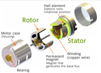
The current-carrying conductors or armature windings are located on the stator. A permanent magnets is attached to the rotor. A BLDC Motor is similar in construction of synchronous motor except the rotor is a permanent magnet. The magnetic field generated by the stator and the rotor revolve at the same frequency. The rotor with permanent magnent is more efficient in operation compared to the electrical commutation to convert electrical energy into mechanical energy. Hall sensors are also known as rotary encoders, used to sense the position of the rotor.
Working:
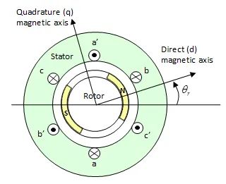
BLDC motor works on the principle similar to that of a Brushed DC motor. It works on the principle of Lorentz Law, which states that “the current carrying conductor placed in a magnetic and electric field experience a force". As a consequence of reaction force, the magnet will experience an equal and opposite force. In the BLDC motor, the current carrying conductor is stationary and the permanent magnet is rotating. The rotor position feedback from the Hall sensor helps to determine when to switch the armature current for position control.
Advantages of BLDC Motor:
* High efficiency
* Less maintenance due to absence of brushes
* High speed can be achieved
* Low noise during operation
* Better speed vs torque characteristics
Limitations:
* These motors are costly
* Electronic controller is required
* Limited to high power otherwise, heat weakens the magnets and the insulation of winding may get damaged.
* Additional sensor is used
Applications of Brushless DC Motors:
* High speed applications
* Variable speed applications
* Position control applications
* Computer hard drives and DVD/CD players
* Electric vehicles, Hybrid vehicles, and electric bicycles
* Industrial robots, CNC machine tools
* Washing machines, compressors and dryers
* Fans, pumps and blowers.