Final Project: Design of an Electric Vehicle
Design of an Electric Vehicle
Objective:
To create a MATLAB model of electric car which uses a battery and a DC motor
1. System level configurations
2. Model parameters
3. Results
4. Conclusion
Electric Vehicle:
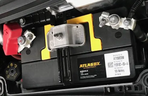
Battery electric vehicles are also known as pure electric vehicle. The BEVs rely only on battery power. These vehicles do not have internal combustion engines. These engines do not have any exhaust system and produce zero emissions during operation. Since there is no internal combustion engine, the battery needs to be charged by plugging it in.
A BEVs have to be plugged in, and charging can take a long time without a fast charging station, it is the only natural to be concerned about range. BEV range has increased the range in the recent years. Some of the BEV can be driven up to 400 miles on a single charge. Even the most affordable BEVs provide around 100 miles on a charge though, making them well-suited to city driving and moderate commutes. Longer trips require some pre-planning depending on the range of the BEV. The increase in charging station and reduction in the charging time can overcome the limitations of BEV.
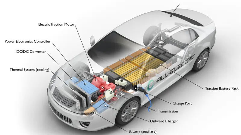
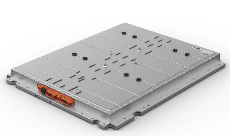
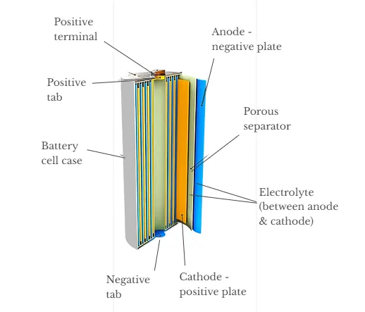
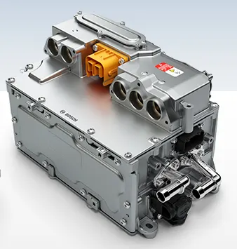
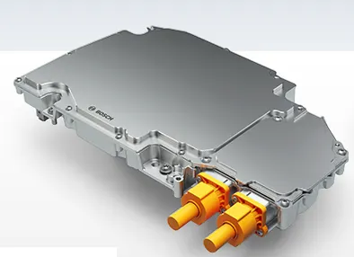
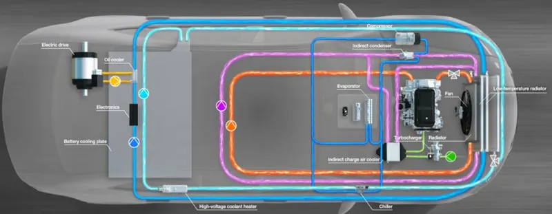
The major parts of an EV are
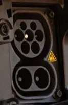
* Rapid AC chargers: Rapid AC chargers provide power at 43 kW (three-phase, 63A) and use the Type 2 charging standard. Rapid AC units are typically able to charge an EV to 80% in 20-40 minutes depending the model’s battery capacity and starting state of charge.
* Rapid DC chargers: Rapid DC chargers provide power at 50 kW (125A). These are the most common type of rapid EV charge points. Both connectors typically charge an EV to 80% in 20 minutes to an hour depending on battery capacity and starting state of charge.
* Ultra-rapid DC chargers: Ultra-rapid DC chargers provide power at 100 kW or more. These are typically either 100 kW, 150 kW, or 350 kW. These are the next-generation of rapid charge point, able to keep recharging times down despite increase in battery capacities.
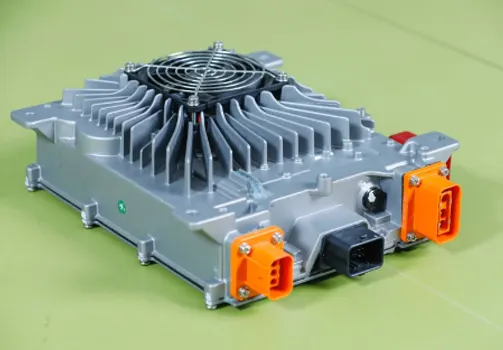
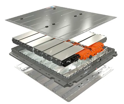
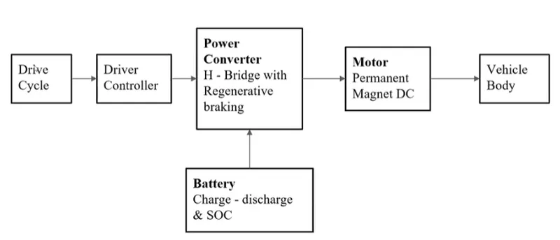
Block Diagram:
Simulink model:
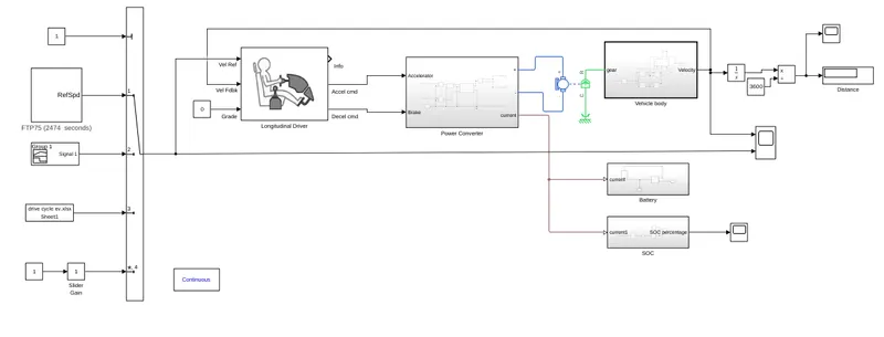
The Simulink model consists of Vehicle body subsystem, Power Electronics converter subsystem, Electric motor, Battery sub system, SOC subsystem, Types of Inputs that can be connected to the longitudinal driver block. The multiple switch is closed in such a way that the drive cycle input is connected to the longitudinal driver block. The blocks of subsystem and the block parameter of the blocks are explained as follows
Vehicle body subsystem:
The Vehicle subsystem is designed to have the gear input and the velocity output. The Gear input of the Vehicle block is connected to the rod of motor (rotating part). The velocity output is given as a feedback to the longitudinal driver block and also the output can be viewed using the scope.
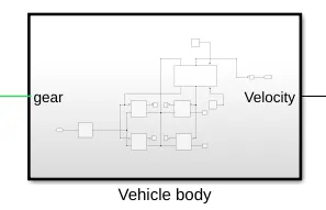
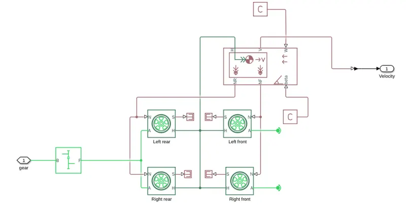
The vehicle body subsystem consists of four Tire blocks to represent the four wheels of the car, simple gear, vehicle body block.
Simple gear:
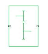
B - Mechanical rotation port associated with Base shaft
F - Mechanical rotation port associated with Follower shaft
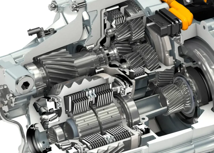
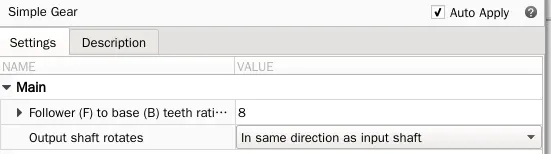
The simple gear is used to change the increase or decrease the speed depending on the value of gear, gear ratio, gear efficiency. It is connected between the rotating part of the motor and the axle.
Parameters:
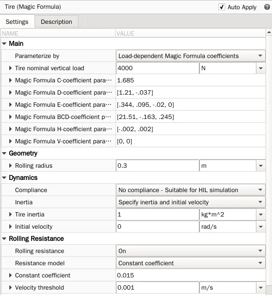
Tire (Magic Formula):
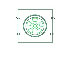
N - Normal Force
S - Slip between Tire and road
A - Axle for Mechanical rotation
H - Mechanical translational Wheel hub
The Tire block represents the four wheels of the motors. The normal force (N) of two wheels are connected to the front axle normal force (NF) in the vehicle body. The normal force (N) of other two wheels are connected to the rear axle normal force (RF) in the vehicle body. Mechanical translational hub of all wheels are connected to the horizontal motion of the vehicle body.
Parameters:
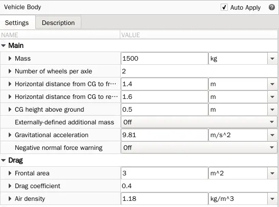
Vehicle Body Block:
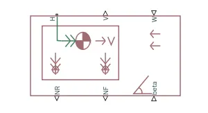
W - Head wind speed
beta - Road incline angle
NF - Front Axle Normal Force
NR - Rear Axle Normal Force
V - Longitudinal velocity
H - Horizontal motion
The head wind speed is connected to the w input port of the vehicle body. The hill climbing angle can be connected to the physical signal input port (beta) of the vehicle body. The normal forces on the rear wheels and the normal forces on the front wheels are connected to the respective Tire blocks. The horizontal motion of the vehicle body is connected with the horizontal mechanical ports of the Tire blocks. The output velocity for the given input values is obtained, which denotes the speed of the vehicle.
Parameters:
Power converter subsystem:
The Power converter subsystem is connected between the Electrical motor and the longitudinal driver block. The Input to the power converter subsystem is the accelerator and the brake command from the longitudinal block. The positive and negative terminal outputs are connected to the Armature winding of the motor. The current signal is also fed into the battery and SOC subsystems.
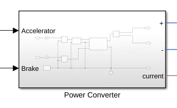
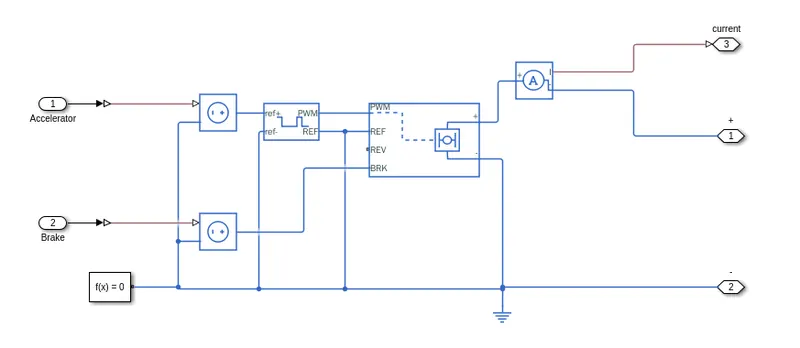
The power converter subsystem consists of H-Bridge block, Controlled voltage source for H-Bridge, Controlled voltage source for PWM voltage controller, Ammeter for measuring the motor current.
H-Bridge:
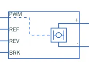
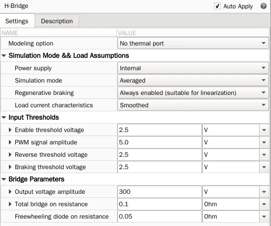
The H-Bridge block output is a controlled voltage that depends on the input signal from the controlled PWM voltage. If the input signal has a value greater than the Enable threshold voltage parameter value, the H-Bridge block output is on and has a value equal to the value of the Output voltage amplitude parameter. If it has a value less than the Enable threshold voltage parameter value, the block maintains the load circuit using Free wheeling.
The signal at the REV port determines the polarity of the output. If the value of the signal at the REV port is less than the value of the Reverse threshold voltage parameter, the output has positive polarity otherwise, it has negative polarity.
Braking mode is invoked when the voltage presented at the BRK port is larger than the Braking threshold voltage. Regardless of whether in PWM or Averaged mode, when in braking mode the H-bridge is modeled by a series combination of two resistances
Parameters:
Controlled PWM voltage:

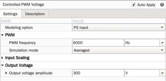
The Controlled PWM Voltage block represents a pulse-width modulated (PWM) voltage source. The block calculates the duty cycle based on the reference voltage across its ref+ and ref- ports. The duty cycle value can be given directly by using an input physical signal port. If the Modeling option is set to Electrical input ports, then the demanded duty cycle is
100∗(Vref−Vmin)/(Vmax−Vmin) %
where,
Vref - reference voltage across the ref+ and ref- ports.
Vmin - minimum reference voltage.
Vmax - maximum reference voltage.
The value of the Output voltage amplitude parameter determines amplitude of the output voltage. At time zero, the pulse is initialized as high, unless the Pulse delay time parameter is greater than zero, or the demanded duty cycle is zero. The parameters Pulse delay time and Pulse width offset can be used to add a small turn-on delay and a small turn-off advance. This can be useful when fine-tuning switching times so as to minimize switching losses.
Parameters:
Longitudinal Driver:
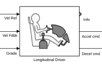
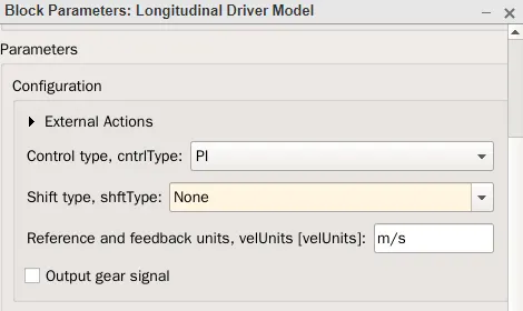
The Longitudinal driver block is used to provide the acceleration and braking command to the power converter. The Reference Velocity input is given from the drive cycle block and the feedback velocity is given from the Vehicle body subsystem. The value of Grade is assumed as zero.
Drive cycle:
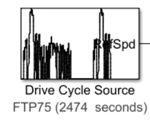
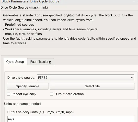
The drive cycle block is used to provide the reference velocity to the longitudinal driver block depending on the selected drive cycle. It has various types of drive cycle that are used to simulate the vehicle performance.
DC Motor:
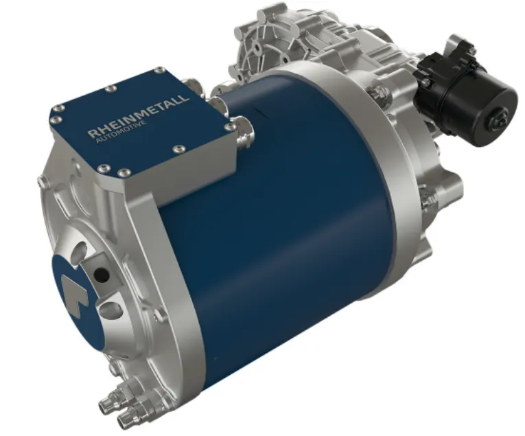
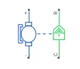
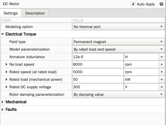
The DC motor block is connected between the Power converter and the Vehicle body subsystem. The positive and negative terminal inputs are connected from the power converter, which provides the supply to armature winding. The mechanical output is connected to the gear box in the vehicle body subsystem.
Battery subsystem:
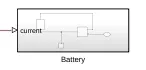
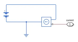
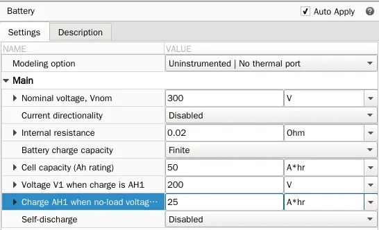
The battery subsystem consists of a Battery block and a controlled voltage. The input current signal is obtained from the Power converter.
Battery:

This block represents a rechargeable battery. Battery charge capacity parameter is infinite, then the block models the battery as a series internal resistance and a constant voltage source. Battery charge capacity parameter is finite, the block models the battery as a series internal resistance plus a charge-dependent voltage source defined by
V = Vnom*SOC/(1-beta*(1-SOC))
SOC - State of charge
Vnom - Nominal voltage
Battery SOC Subsystem :
The Battery SOC subsystem is connected with the current signal from the power converter. The output of the SOC subsystem is connected with a scope to view the SOC percentage for the given Inputs.
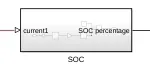
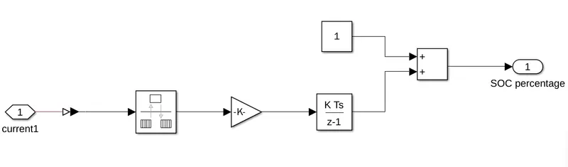
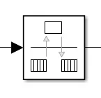
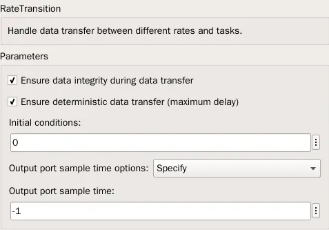
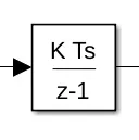
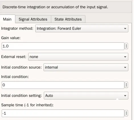
The Battery SOC subsystem consists of Rate Transition block, Discrete Time Integrator block, Gain block to calculate the state of charge of the battery.
Rate Transition:
Discrete Time Integrator:
Gain:

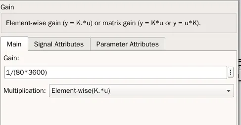
The Rate Transition block, Discrete Time Integrator block, Gain block parameters are given to the corresponding blocks to get the output for the state of charge subsystem. The state of charge from the SOC subsystem can be viewed using a scope.
Result:
Scope 1: Output velocity
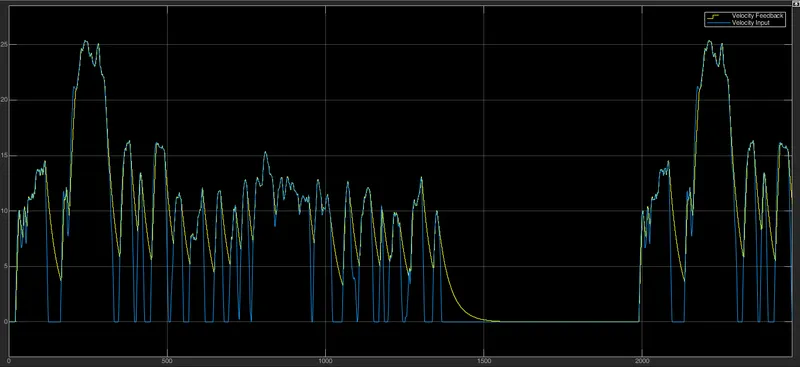
Velocity vs Time
The graph is simulated between the velocity and time period 2474 seconds, which is the total duration of FTP 75 drive cycle. The yellow color represents the velocity of the drive cycle input. The blue color represents the velocity obtained from the vehicle body subsystem.
Scope 2: Distance vs Time
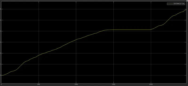
Distance vs Time
The velocity obtained from the vehicle body is converterd from kmph(kilometer per hour) to kmps(kilometer per second) and the resultant value is integrated to obtain the distance output. The value of distance increase with respect to the acceleration command from the longitudinal block.
Scope 3: State of charge of Battery
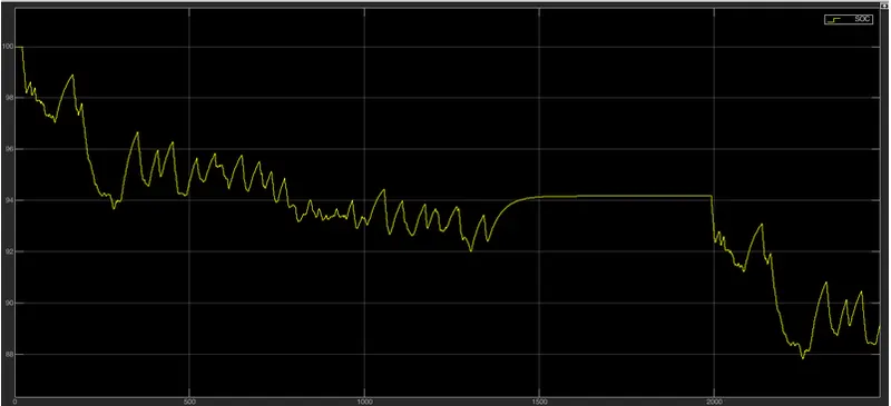
SOC vs Time
Conclusion:
Thus the Battery Electric Vehicle is designed and simulated using the necessary blocks. Suitable parameter values are given to the required blocks and the simulation is completed. The outputs of velocity of the vehicle, Distance converted by the vehicle, State of charge of the battery are obtained for the given drive cycle input.