Project
BAJA All-Terrain Vehicle.
Objective: To prepare a technical report to explain the properties of BAJA All Terrain Vehicle model and to make relevant explanations for the outputs.
All-Terrain Vehicle:
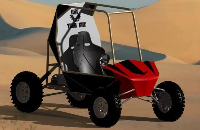
All-Terrain Vehicle consists of four wheels that travels on low pressure tires that are designed and developed to check its characteristics under rough conditions. In our model analysis Continuous Variable Transmission system is used to attain better Torque and Speed characteristics.
Major components used for Simulation:
Generic Engine:
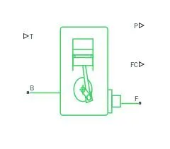
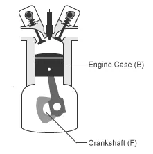
It is an Internal combustion engine with Throttle, Rotational inertia and Time lag. A Throttle physical signal input (T) specifies the engine torque. The Crankshaft (F) transmits the power generated from the combustion process. The Engine block (B) is the physical body that contains the piston cylinders.
The physical signal is given to the Throttle from the Signal builder. Mechanical rotational reference is connected to the engine block . The output from the Engine crank shaft is connected to a variable ratio gear with an inertia block.
Engine sensor (subsystem) :
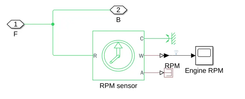
The Engine sensor is connected between the crankshaft output from the Generic engine and the base drive shaft (B) of Variable ratio transmission with an Input shaft inertia. It consists of an Ideal rotational motion sensor which converts the mechanical input given in rod (R) to the angular velocity (W). A physical signal to Simulink converter is used to convert the angular velocity (W). A scope to view the engine speed in graph.
CVT (subsystem):
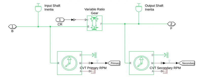
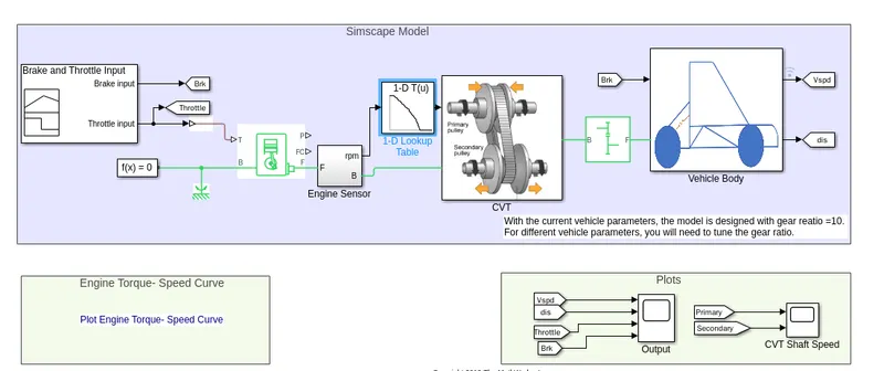
The CVT consists of Variable gear ratio, Input shaft inertia, Output shaft inertia, Two Ideal rotational motion sensors in CVT primary and CVT secondary.
The gear ratio generated from the signal builder is converted into a physical signal using Simulink to physical signal converter and fed into the Input physical signal (r). The mechanical rotational output from the generic engine is connected to Base drive shaft of the variable gear ratio. The follower drive shaft (F) is connected to a simple gear.
An Ideal rotational motion sensor is connected with the Input shaft (Base drive shaft) to measure the speed of the input shaft. Another Ideal rotational motion sensor is connected with the Output shaft (Follower drive shaft) to measure the speed of the output shaft. The case of the Ideal rotational motion sensors are connected to Mechanical rotational references.
Simple gear:
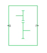
A simple gear is connected between a CVT (subsystem) and a vehicle (subsystem). The Follower shaft to Base shaft ratio was set to 10. The Base shaft of the simple gear is connected to the Follower drive shaft of the variable ratio gear in CVT subsystem. The Follower shaft of the simple gear is connected to the Axle (A) of the Tire (Magic Formula) block.
Vehicle Body (subsystem):
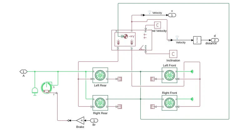
It consists of four Tire (Magic Formula) blocks for the left front, left rear, right front, right rear, Vehicle Body Block, Double Shoe Brake and an Inertia Block connected to the shaft.
Tire (Magic Formula):
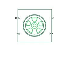
N - Normal Force
S - Slip between Tire and road
A - Axle for Mechanical rotation
H - Mechanical translational Wheel hub
Tire (Magic Formula) Block is created using a Tire Road Interaction (magic formula) connected with wheel and axle, Translational spring and a Translational damper. The rated vertical load ,peak longitudinal force at rated load, slip at peak force at rated load, rolling radius, Inertia, rolling resistance values are modified in the parameters of Tire (magic formula).
Vehicle Body Block:
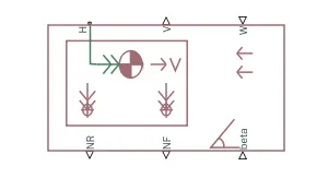
W - Head wind speed
beta - Road incline angle
NF - Front Axle Normal Force
NR - Rear Axle Normal Force
V - Longitudinal velocity
H - Horizontal motion
The vehicle body block is connected with the simple gear. The Thrust generated by the Tire(magical block) is transmitted from the Hub (H) of the wheel to the Horizontal motion (H) of the Vehicle body. Front axle Normal force (NF) is connected to the Normal force (N) of the left and the right Tire (magic blocks). Rear axle Normal force (NR) is connected to the Normal force (N) of the left and the right Tire (magic blocks). The physical signal input port for road incline angle (beta) is connected to physical constant. The physical signal input port for headwind speed (w) is connected to a physical constant. The output Longitudinal velocity (v) from the vehicle body block can be connected to a scope using physical to Simulink converter.
Double Shoe Brake:
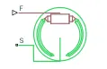
F - Actuating Force
S - Drum Shaft Rotation
The Double shoe brake is connected between the brake input from the Signal builder and the output shaft. The output from the Signal builder is connected to the Actuating Force (F) of the Double Shoe Brake using a Simulink to physical system converter and a Gain. Drum Shaft Rotation (S) is connected to the output shaft from the simple gear and the axle of four Tire (magical block).
Types of model :
BAJA ATV without Dashboard.
BAJA ATV with Dashboard.
BAJA ATV with Lookup Table.
BAJA ATV with Lookup Table and Dashboard.
Case:1 BAJA ATV without Dashboard.
Simulink model:
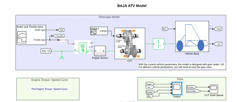
Signal Builder: 1
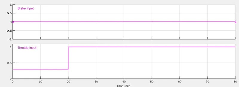
The Brake and the Throttle inputs are created using a Signal builder. The Throttle signal is converted into a physical signal and fed to the Generic Engine. The Brake signal is connected to a Double shoe brake through a gain block and a Simulink to physical converter.
Signal Builder: 2
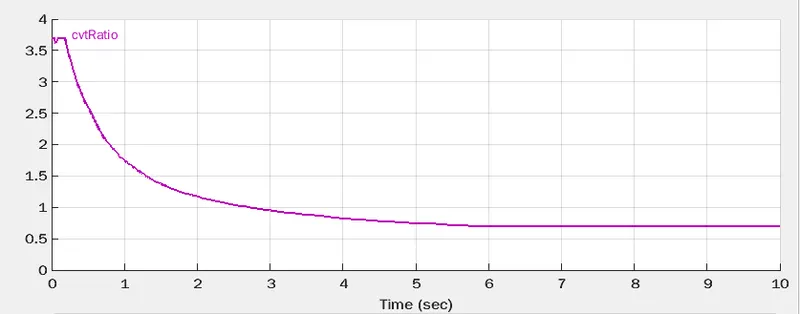
The continuously varying Transmission ratio is created using this Signal builder. The CVT ratio output is fed as input to a variable ratio gear using a Simulink to physical converter. This physical signal port associated with the input to output shaft ratio.
Observation:
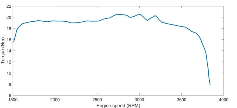
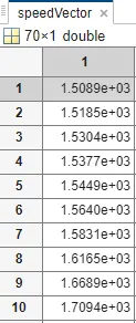
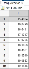
The Torque and Speed values are given as a vector input to the Generic Engine from the MATLAB Work space using the given Speed and Torque curve.
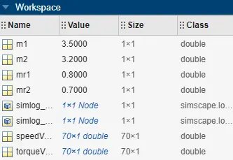
The values obtained from the graph can be viewed in the MATLAB workspace.
Output:
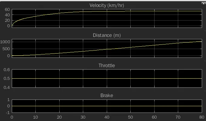
During zero Break value and constant Throttle value of 0.5, the distance will increase linearly and the speed increases to 55 km/hr. After reaching the steady state, the value becomes constant. The rate of increase of speed depends on the Throttle and the Input to the variable ratio gear.
CVT Shaft Speed:
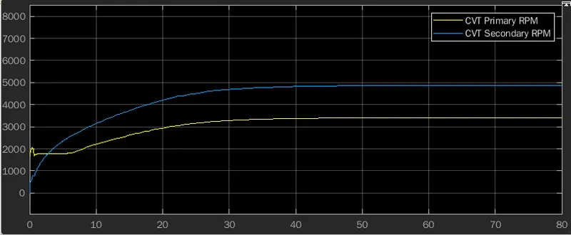
The speed difference between the CVT primary and the CVT secondary can be observed from the above plot.
The Initial speed of the CVT primary is higher than the CVT secondary.
The Final speed of the CVT secondary is higher than the CVT primary.
Case:2 BAJA ATV with Dashboard.
In this model, variable inputs are used for throttle and brake to check the characteristics of the model by varying the parameters in the run time of the model. Engine RPM meter is used to view the engine rpm in real time and a speedometer is used to view the velocity of the vehicle.
Simulink model:
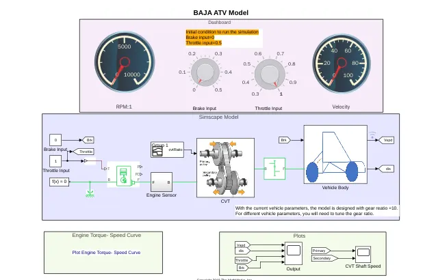
Dashboard:
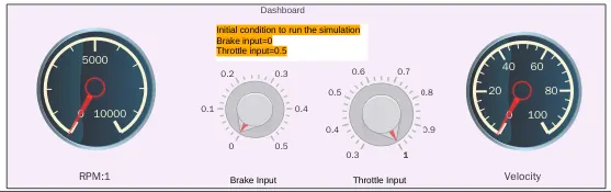
It consist of two Gauges and two Knobs. One Gauge is used to view the Engine rpm and another Gauge is used to view the Velocity of the vehicle. One Knob is used to control the Brake input and another Knob is used to control the Throttle input.
Output:
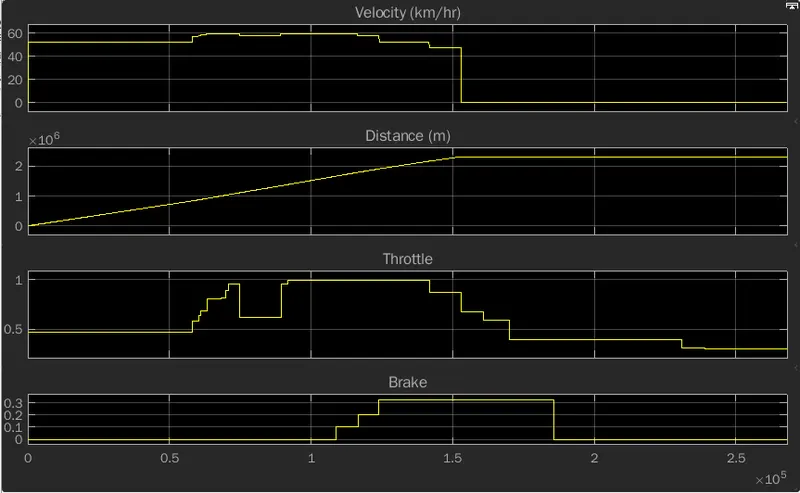
The change in Velocity, Distance, Throttle and Brake values are obtained for the corresponding change in the Throttle and Brake Knobs.
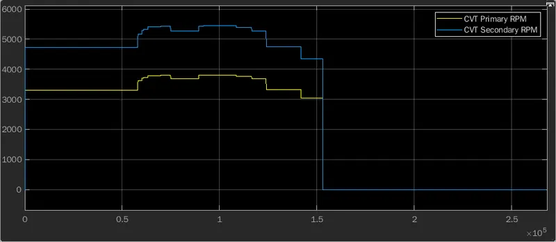
CVT Shaft Speed:
The change in primary CVT and secondary CVT are obtained for the corresponding changes in the Throttle and Brake inputs. During the variation in Throttling and Braking, the secondary CVT speed is higher than the primary CVT speed.
Case:3 BAJA ATV with Lookup Table.
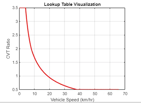
In this model, the input to the Variable Ratio Gear is given using a Lookup Table. The Output velocity from the vehicle body is connected as an input to the Lookup Table forms a closed loop in the model. The Input to the Continuous Variable Transmission system is changed from a Signal builder to a Lookup Table and the Dashboard are the major changes from the previous case.
Simulink model:
Lookup Table:
A lookup table is an array of data that maps input values to output values by approximating a mathematical function.
1-Dimensional Lookup Table is used to vary the physical input to the variable ratio gear.
Output:
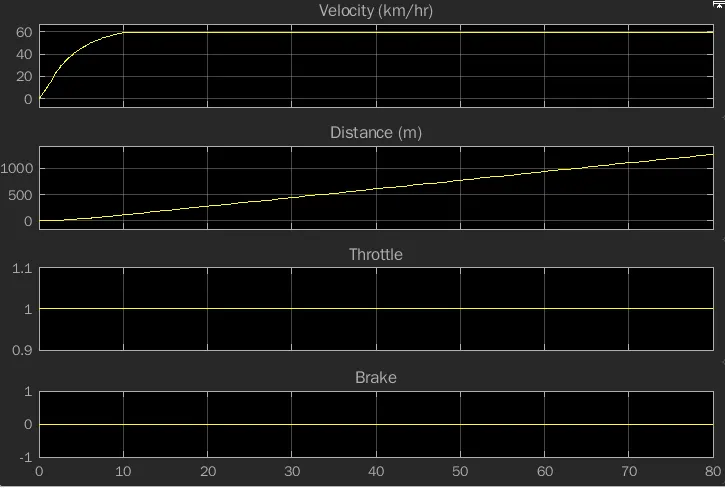
In the above graph, the CVT ratio is varied using the values from the Lookup Table and the corresponding changes in the values of Velocity, Distance, Throttle and Brake are obtained.
CVT Shaft Speed:
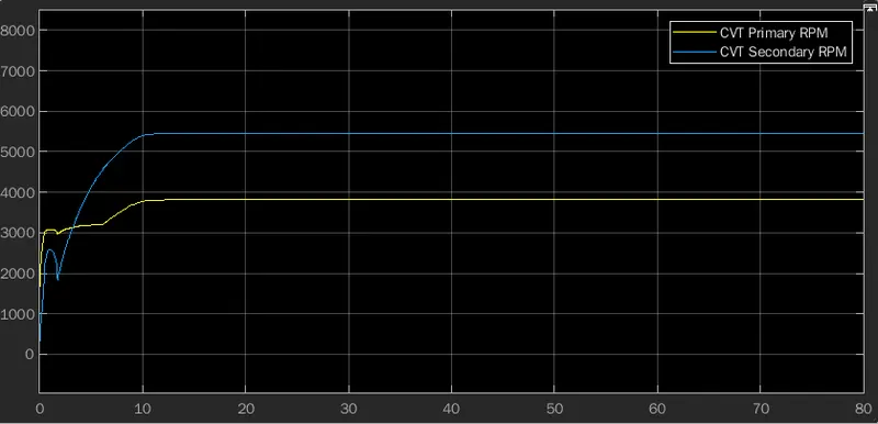
In the above graph, the Initial Speed of primary CVT is greater than the secondary CVT.
After attaining steady state the speed of secondary CVT is greater than the primary CVT.
Case4: BAJA ATV with Lookup Table and Dashboard.
Simulink model:
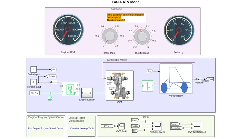
In this model the combination of the Lookup Table and the Dashboard is used. The Output from the Throttle and Brake Knobs from Dashboard are used to control the Generic Engine. The Output from the Lookup Table is used to control the CVT ratio.
Output:
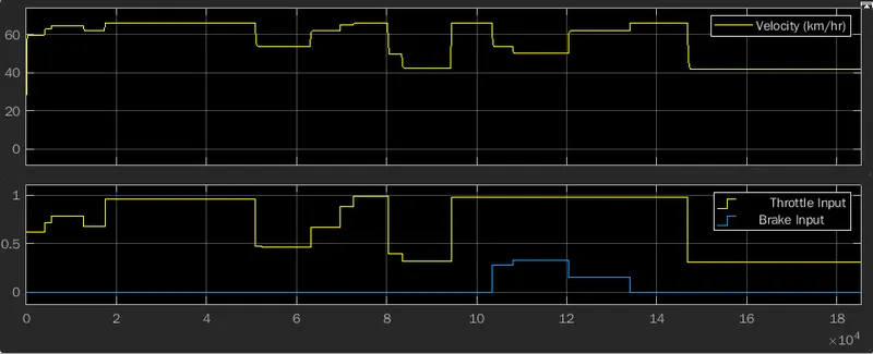
From the above output, the variation in the Velocity, Throttle output and Brake output are obtained for the corresponding changes in the Throttle knob and the Brake knob.
CVT Shaft speed:
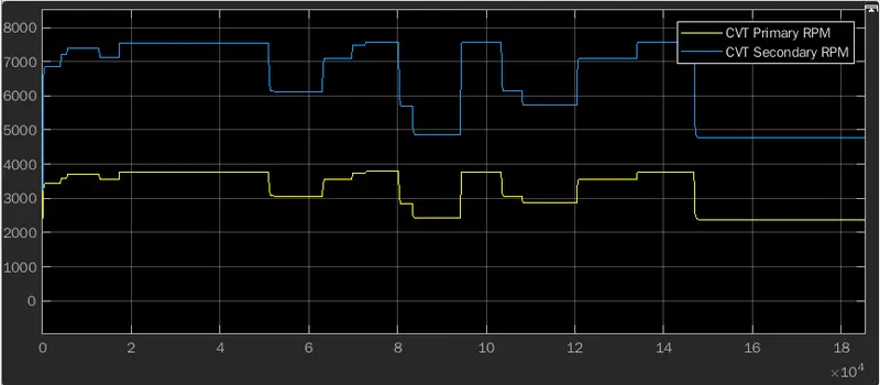
From the above output, the speed of secondary CVT is always higher than the speed of the primary CVT for the corresponding changes from the Throttle knob and Brake knob.
Conclusion: Thus the types of BAJA All-Terrain Vehicles are analyzed for the various input and the corresponding outputs are obtained.