Project 1 Mechanical design of battery pack
Mechanical design of battery pack
Objective: To prepare a detailed battery pack drawing along with its enclosure for Battery pack (ANR26650M1-B) with the capacity of 18 kWh
Cell Specifications: Model Number - ANR26650M1-B
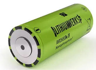
It is a high-performance Nano phosphate lithium iron phosphate (LiFePO4) battery technology that can deliver high power and energy density combined with excellent safety performance and extensive life cycling in a lighter weight, more compact package. The cells have low capacity loss and impedance growth over time as well as high usable energy over a wide state of charge range, which makes the systems to meet end of life power and energy requirements with minimal pack over sizing.
Applications:
* It is used in commercial applications such as Datacenter in UPS, Telecom backup and IT backup.
* Industrial robotics and material handling equipment
* Military vehicles and Military power grids
* Frequency regulation, Renewables integration, Reserve capacity, Transmission and distribution
* Hybrid, plug-in hybrid and electric vehicle battery systems for Commercial vehicles and Off-highway vehicles
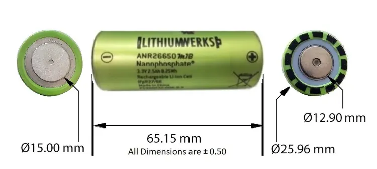
Dimensions:
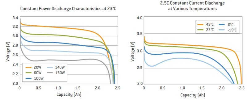
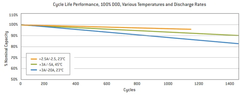
Characteristics of ANR26650M1-B:
Data sheet:
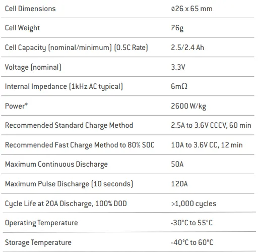
Calculations:
Battery energy = 18 kwh (Given)
The Nominal voltage of battery pack = 300 Volts (Assumption)
The Nominal voltage of one cell = 3.3 V
Capacity of each cell = 2.5 Ah
Total cells:
Total number of cells N = energy / (nominal voltage * capacity)
N = 18000 / (3.3 * 2.5)
N = 2182
2182 cells are required to get 18 kWh energy
Series cells:
Number of series cells Ns = Nominal voltage of battery pack / Nominal voltage of one cell
Ns = 300 / 3.3
Ns = 90.9 = 91 cells
91 cells are connected in series
Parallel cells:
To generate 300 voltage but the capacity of the whole module will be 2.5 Ah
To find the number of cells to be connected in a parallel configuration
Number of parallel cells Np = Total cells / Ns
Np = 2182/91
Np = 23.9 = 24 cells
24 cells are connected parallel
Cell architecture:
For the battery pack with 91 Series and 24 Parallel cells
Cell architecture is 91S24P
Battery capacity:
Capacity = Number of parallel cell * individual cell capacity
= 24 * 2.5
Capacity = 60 Ah
From the data sheet,
Cell Diameter = 26mm
Cell Height = 65mm
Casing:
Length of casing (L) = number of cells at series * (cell diameter + margin at both side) +clearance at side
L = 91 * 30 + 60
L = 2790 mm
Breadth of casing (B) = number of cells at parallel* (cell diameter + margin at both side + clearance at side
B = 24 * 30 + 60
B = 780 mm
Height of casing (H) = Height of cell + margin for cell wiring, Cell holders and metal strips
H = 65 + 35
H = 100 mm
Weight of battery pack:
Cell weight = 76g = 0.076 kg
Number of the cells = 2182
Battery pack weight (W) = cell weight * Number of cells + weight of accessories
W = 0.076 * 2182 + 4.5
= 165.8 + 4.5
W = 170.3 kg
Cell Holder:
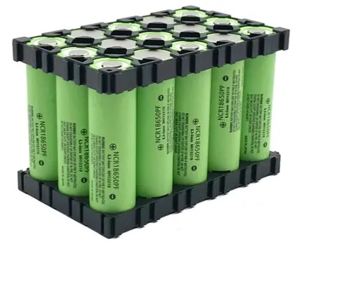
The main function of a battery holder is to keep cells fixed safely and securely. It is used to keep cells in a proper arrangement so that there will be a decrease in mechanical vibration, and have a better thermal runway in between the gaps of the cell. Most of the cell holder is made up of polypropylene or nylon bodies rated for 80-100 °C
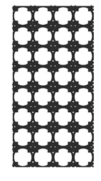
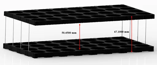
The cells need to be arranged depending on the cell architecture. The cell architecture determines the number of cells to be connected in series and number of cells to be connected in parallel. The cells are arranged accordingly over the lower cell holder.
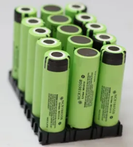
After the arrangement of series and parallel connection of cells in the battery pack, the upper cell holder is fixed over the cell arrangement. It keep the cells in a proper arrangement so that there will be a decrease in mechanical vibration and a thermal ventilation between the cells.
Spot welding:
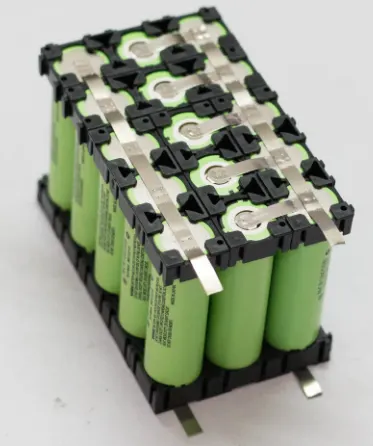
Internal Connections between cells are done using nickel strips which are welded to the cell terminals or the case. Soldering is not recommended as it can transfer uncontrolled amounts of heat to the battery components which can damage the separators or the vents made of plastic. Modern computer controlled resistance welders allow much more precise control of the welding process. They can limit the amount of heat applied to the battery and keeps the heat to a small desired area. Welding also provides a stronger and low resistance joint. The interconnecting strips often have complex shapes and profiles which may be stamped out of the flat strip in a progressive die.
Battery management system:
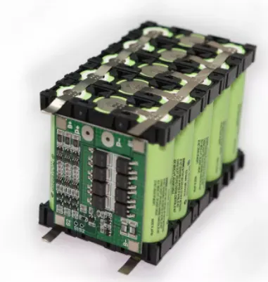
Lithium-ion batteries have higher energy density than other battery chemistries. These batteries also have the risk of fire under unusual circumstances. It is mandatory to operate the EV batteries in safe limits to ensure the safety of the user and the vehicle. The Battery Management System continuously monitors temperature, voltage and current of the pack to ensure it is being operated in safe conditions. BMS is responsible for thermal management of the battery and monitors its temperature continuously. BMS can adjust cooling and trigger other safety mechanisms to minimize the risk. The battery management system is fixed along with the battery pack to ensure the safety and reliable operation of the battery pack.
Cooling structure:
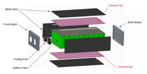
The Battery pack should be stored in a controlled surrounding for increasing the safety, performance and lifespan of the battery pack. When the temperature is controlled, there is no risk of thermal runaway. Due to continuous driving and charging of an EV, battery cells will produces heat. This heat should be removed from the battery pack. When battery temperature reaches the optimum temperature. Under these situations cooling systems are used in the battery pack of EV. Indirect contact systems are preferred in order to achieve better isolation between battery module and surroundings to make better safety performance. Depending on the heat sinks used for cooling, liquid systems can also be categorized into either passive system or active system.
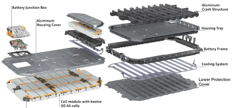
Battery Enclosure:
The growth of electrification brings many new challenges to design and manufacture a robust battery enclosure. An efficient battery enclosure has many attributes that aid passenger and battery safety, assist in thermal management. It should protect the battery from any abnormal conditions. The battery enclosure must be designed within the financial and weight constraints of the vehicle.
Conclusion:
Thus the detailed battery pack drawing along with its enclosure for Battery pack, calculation for the number of cells, Dimension, Weight for the battery pack are explained for the given cell ANR26650M1-B was explained.