Week 7 State of charge estimation
1. To Simulate the 3 test cases from harness dashboard and write a detailed report on the results
BMS closed loop model:
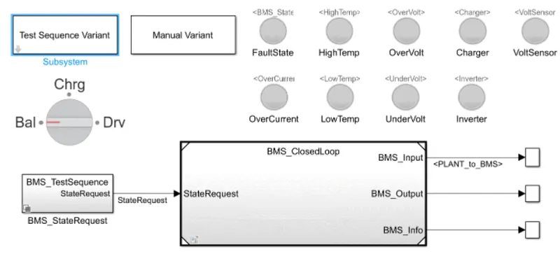
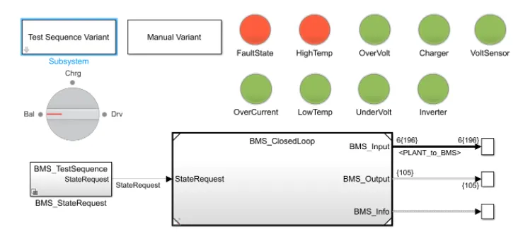
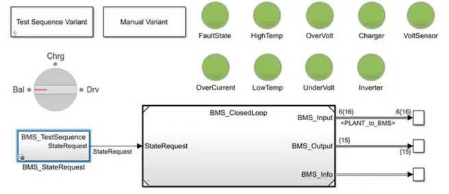
The BMS closed loop model consist of test sequence variant subsystem, manual state request subsystem, BMS closed loop subsystem.
The indication lamps for the battery management system are Fault state, High temperature, Low temperature, Overvoltage, Under voltage, charger, voltage sensor, Inverter.
The Test sequence variant subsystem is used to change the test case parameter. Depending the test case request value the model is simulated and the plots are obtained for Cell voltage, Cell temperature, SOC, Pack current, BMS state and BMS current.
Test case 1:
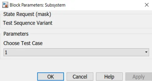
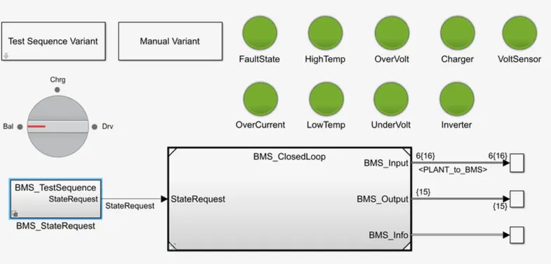
For the given test case, all the indication lamps appear as green. This shows that the all the specified lamps are operating with in the given condition.
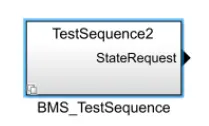
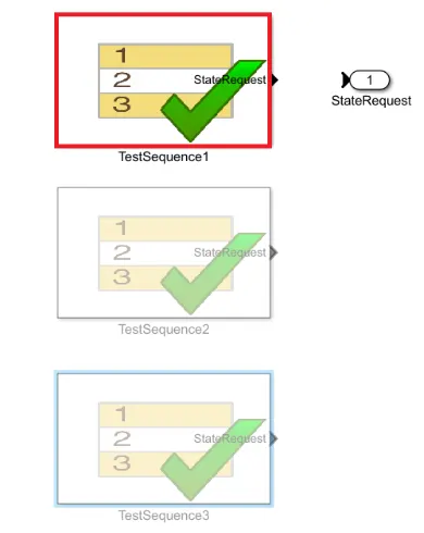
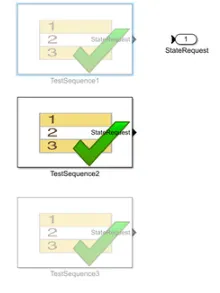
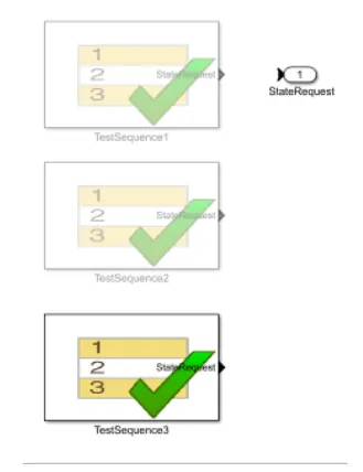
The BMS Test sequence is used to select the state request to the BMS closed loop subsystem.
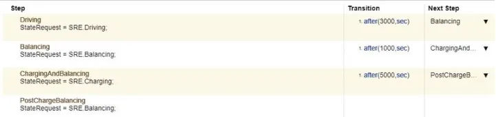
When the simulation begins, the vehicle is in driving state and the SOC will decrease for this time period. After a time period of 3000 seconds the next step is balancing mode and the vehicle is in standby condition. After, another 1000 seconds, the vehicle is in charging phase and the battery's SOC increases almost to 100%. The next phase is the post charging phase in which the vehicle again goes for the standby mode
Output:
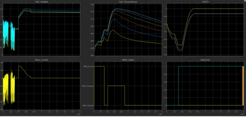
Cell voltage: In driving mode, voltage drops between 3.9 and 3.1 in all cells. From 3000 to 4000 seconds, the vehicle is in Balancing state, in this mode the cells settles at its nominal voltage 3.7V. In charging mode, the voltage increases up to 4.2V and becomes constant when it reaches the balanced state.
Cell temperature: The cell temperature increases during driving and discharging of the cell.
SOC: In the driving mode the SOC decreases from 80% to 45%. In the balancing mode the SOC gets settled at 45%. After that charging and balancing mode the SOC will increases to 100%
Pack current: It varies from 70A to 10A when the vehicle enters into balancing mode then the current of the pack settles at zero. In charging and balancing mode activates, the pack current will Increases up to 30A and then gradually starts decreasing to zero and enters into post charge balancing mode.
BMS state: It indicates the state of charging, discharging, balanced state of the battery management system.
BMS command: It changes the value to 1 depending on the balancing commands.
Test case 2:

Output:
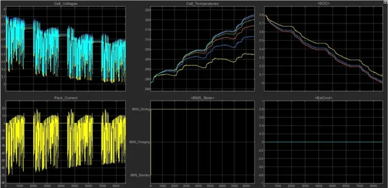
Cell voltage: In this mode, the voltage level is varying from 3.2V to 3.9V during starting. But due to continues driving there is a gradual decrease in the voltage ranges also so we can see that at end the voltage varies from 3.1V to 3.7V.
Cell temperature: The cell temperature increases up to complete discharging of the cell and decreases to zero after completely discharged.
SOC: Initial SOC is 80% during stating. Due to increase in driving time of 10000 seconds, the SOC became 0% at 8692seconds.
Pack current: It varies from 70A to 15A in the starting condition. Due to long running time, the current varies from 55A to 20A and ends after SOC reaches to 0% as there is no charge to supply.
BMS state: It indicates only the driving mode of the battery management system.
BMS command: It changes the value to 1 depending on the balancing mode, which occurs after complete charging.
Test case 3:

Output:
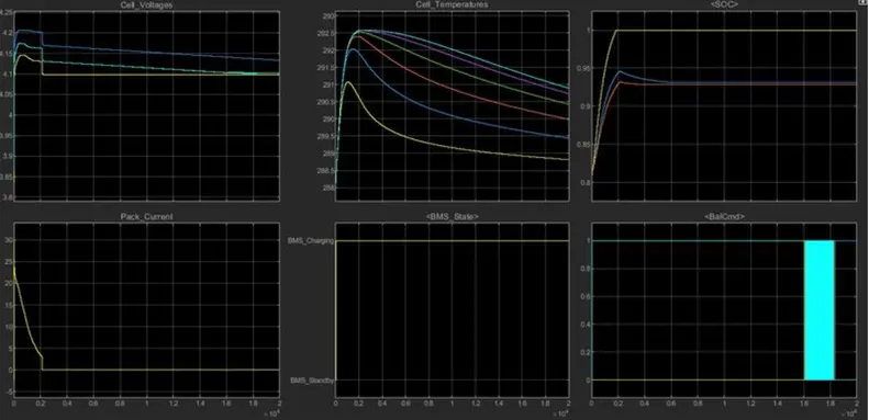
Cell voltage: In this mode, the voltage level is varying from 3.2V to 3.9V during starting. But due to the continues charging, there is a gradual increase in the voltage and attains 4.2 V
Cell temperature: It can be observed that while battery is in charging condition there is a increment in the temperature of the cells. But after the battery is full charged the temperature values becomes balanced.
SOC: Initial SOC is 80% during starting. Due to charging, the SOC became 100%.
Pack current: It increases up to 20 A during charging. After completely charged, the pack current becomes zero.
in the starting condition. Due to long running time, the current varies from 55A to 20A and ends after SOC reaches to 0% as there is no charge to supply.
BMS state: It indicates only the charging mode of the battery management system.
BMS command: It changes the value to 1 depending on the balancing mode, which occurs after complete charging.
2. To implement BMS coulomb counting for SOC estimation
BMS model:
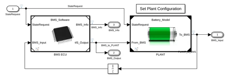
BMS ECU:
The ECU of the battery management system act as a control unit for the battery management system. The State request and the BMS inputs are the input data to the ECU unit. The BMS information from the ECU is connected to an outport block for transferring the BMS information. The BMS output is connected to the plant subsystem of the BMS model.
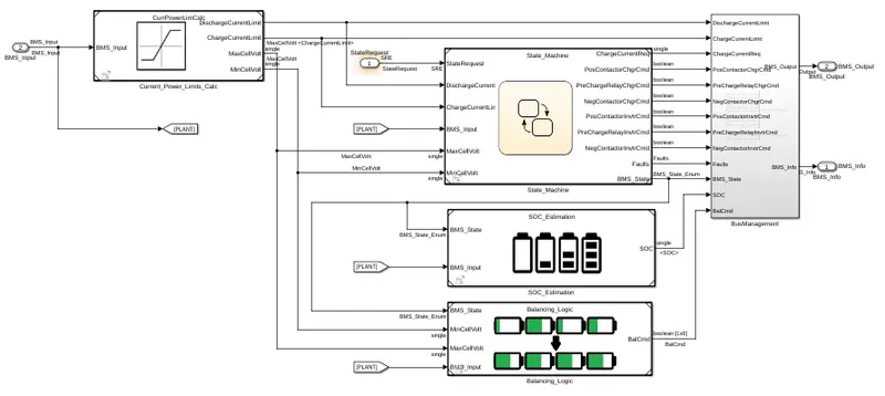
SOC Estimation subsystem:
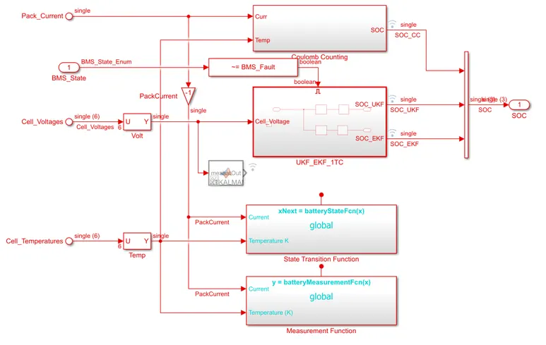
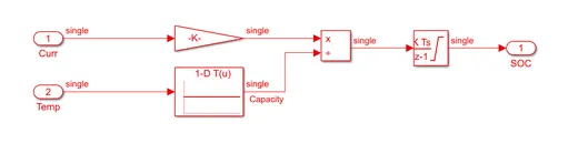
Coulomb counting subsystem: The coulomb counting subsystem is used to calculate the SOC using the peak current and the cell temperature.
Coulomb counting:
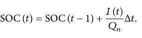
Coulomb counting is a technique which is used to track the State of Charge of a battery pack. It works by integrating the active flowing current over time to derive the total sum of energy entering or leaving the battery pack. It is measured in Ampere hour. The Coulomb counting method measures the discharging current of a battery and integrates the discharging current over time to estimate the SOC.
where,
SOC(t-1) - Previously estimated SOC values.
I(t) - Discharging current.
Qn - Charge capacity of the battery.
Δt - Change in time.
Modified Coulomb counting method:
To improve the Coulomb counting method, a new technique called modified Coulomb counting method is proposed. The modified Coulomb counting method uses the corrected current to improve the accuracy of estimation. The corrected current is the function of discharging current. There is a quadratic relationship between the corrected current and discharging current of battery. By practice of experimental data, corrected current is calculated by the following form.

where
Ic(t) - Corrected current.
K1, K2, KO - constants values obtained from the practice experimental data.
I(t) - Discharging current.
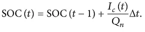
In modified Coulomb counting method, SOC is calculated by the following equation
where,
SOC(t-1) - Previously estimated SOC values.
Ic(t) - Corrected current.
Qn - Charge capacity of the battery.
Δt - Change in time.
The experimental results show that the accuracy of the modified Coulomb counting method is superior to the conventional Coulomb counting method.