Project 2 Thermal modeling of battery pack
Thermal modelling of battery pack
Objective: To create a Simulink model for a 10 cell series lithium ion battery model to simulate the thermal effects and to compare life cycle performance at various temperatures, charge & discharge rates.
Thermal modelling of battery pack:
The Battery pack should be stored in a controlled surrounding for increasing the safety, performance and lifespan of the battery pack. When the temperature is controlled, there is no risk of thermal runaway. Due to continuous driving and charging of an EV, battery cells will produces heat. This heat should be removed from the battery pack. When battery temperature reaches the optimum temperature. Under these situations cooling systems are used in the battery pack of EV. Indirect contact systems are preferred in order to achieve better isolation between battery module and surroundings to make better safety performance. Depending on the heat sinks used for cooling, liquid systems can also be categorized into either passive system or active system.
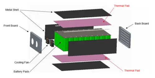
The growth of electrification brings many new challenges to design and manufacture a robust battery enclosure. An efficient battery enclosure has many attributes that aid passenger and battery safety, assist in thermal management. It should protect the battery from any abnormal temperature. The battery enclosure must be designed within the financial and weight constraints of the vehicle.
Simulink model:
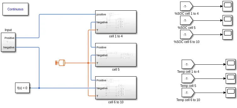
The Simulink model consists of an input subsystem, subsystem for cells 1 to 4, subsystem for cell 5, subsystem for cells 6 to 10, Thermal mass, Powergui block, solver configuration block, separate scopes to display the outputs for different set of cells.
Input subsystem:

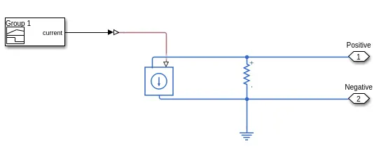
The input subsystem consists of a signal builder, controlled current source, Simulink to PS converter, resistor and an electrical reference. The input subsystem consists of positive, negative terminals to which the series combination of cells are to be connected.
Signal Builder:
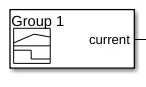
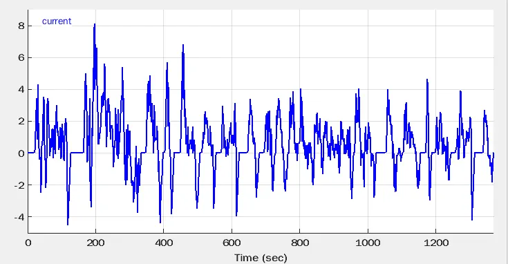
The Signal builder is used to generate the UDDS drive cycle input using the values imported from the Excel sheet. The Distance is given as an input of time in x-axis and the speed is given as an input of current in y-axis.
Controlled current source:

It is connected to the battery with a series resistance of 1 ohm. The physical signal input to the current source is given from the signal builder. The current source is connected to the series combination of the cells.
Resistor:

The resistance value is 1 ohm as per the default parameter. It is connected across a controlled current source and the series combination of cells.
Cell 1 to 4 subsystem:
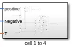
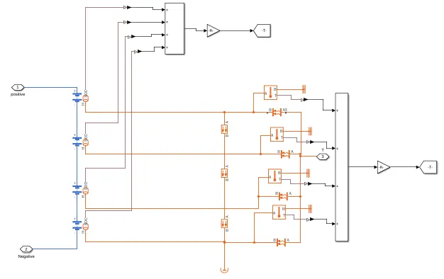
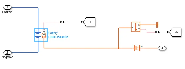
The cell 5 consists of an identical table based battery blocks. It consists of positive, negative and thermal input port. The positive terminal is connected to the cell 1 to 4 subsystem. The negative terminal is connected to the cell 6 to 10 subsystem. The thermal port is connected to the thermal mass.
Cell 5 subsystem:
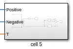
The cell 5 has a table based battery blocks connected in series. It consists of positive, negative and thermal input port. The positive terminal is connected to the negative terminal of cell 5 subsystem. The negative terminal is connected to the controlled current source in the input subsystem.
Cell 6 to 10 subsystem:
The cell 6 to 10 subsystem consists of four identical table based battery blocks connected in series. It consists of positive, negative and thermal input port. The positive terminal is connected to the negative terminal of cell 5 subsystem. The negative terminal is connected to the controlled current source in the input subsystem. The thermal port is connected to the thermal mass.
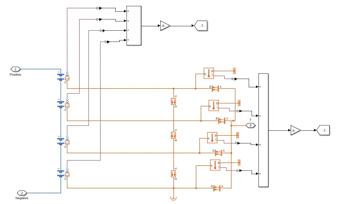
The SOC output from four battery blocks are connected to an add block and the resultant output is divided by the number of battery bocks to get the average SOC. The temperature output from all the temperature sensor are divided by the number of battery bocks to get the average temperature for cells 1 to 4.
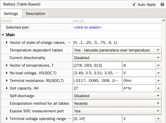
Battery (Table Based):
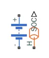
In the main section of the battery parameter, the Expose SOC measurement port is selected to yes to enable the SOC output from the battery block.
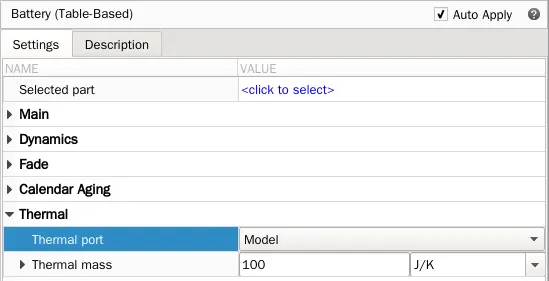
The Thermal port section is changed to model to enable the thermal port in the battery block.
Conductive Heat Transfer:
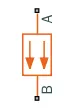
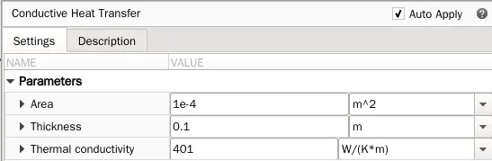
The Conductive Heat Transfer block represents a heat transfer by conduction between two layers of the same material. The transfer is governed by the Fourier law
Q = k * (A / D) * (TA - TB)
where,
Q - Heat flow.
k - Thermal conductivity of the material.
A - Area normal to the heat flow direction.
D - Distance between layers (thickness of material).
TA - Temperature of layer A.
TB - Temperature of layer B.
Connections A and B are thermal conserving ports associated with material layers. The block positive direction is from port A to port B. This means that the heat flow is positive if it flows from A to B. The conductive heat transfer parameter was set to default for the simulation.
Temperature sensor:

The temperature sensor is used to measure the temperature difference between the terminals A and B. In the Simulink model temperature sensor is used to measure the thermal input to the battery block from the convective heat transfer block.
Convective Heat Transfer:

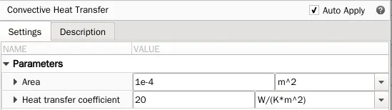
Convective heat transfer is used to transfer the heat from the temperature source to the battery. Depending on the area in the parameter, convective heat flow changes.
Q = k * A * (TA - TB)
where,
Q - Heat flow.
k - Convection heat transfer coefficient.
A - Surface area.
D - Distance between layers.
TA and TB - Temperatures of the two bodies.
Thermal mass:

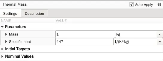
The Thermal Mass block represents a thermal mass, which reflects the ability of a material or a combination of materials to store internal energy. The property is characterized by mass of the material and its specific heat. The thermal mass is described with the following equation:
Q = c * m * (dT / dt)
where,
Q - Heat flow
c - Specific heat of mass material
M - Mass
T - Temperature
t - Time
The mass and specific heat parameters are set to default in the thermal mass parameter for the simulation.
Output:
Scope 1:
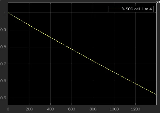
From the plot the SOC of the cells 1 to 4 decreases from the 100 percentage to 52 percentage for the given thermal input and the UDDS input using the controlled current source.
Scope 2:
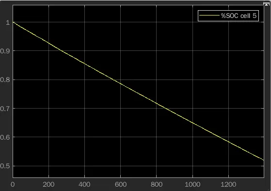
From the plot the SOC of the cell 5 decreases from the 100 percentage to 52 percentage for the given thermal input and the UDDS input using the controlled current source.
Scope 3:
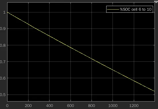
From the plot the SOC of the cells 6 to 10 decreases from the 100 percentage to 52 percentage for the given thermal input and the UDDS input using the controlled current source.
Scope 4:
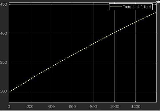
From the plot the temperature of the cells 1 to 4 increases from the 298 k to 434 k for the given thermal input and the UDDS input using the controlled current source.
Scope 5:
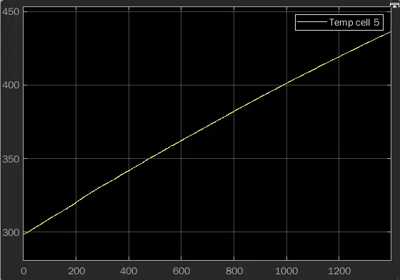
From the plot the temperature of the cell 5 increases from the 298 k to 434 k for the given thermal input and the UDDS input using the controlled current source.
Scope 6:
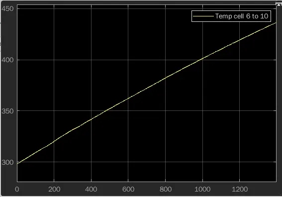
From the plot the temperature of the cells 6 to 10 increases from the 298 k to 434 k for the given thermal input and the UDDS input using the controlled current source.
Conclusion: Thus the 10 cell series lithium ion battery model is simulated and the thermal effects and life cycle performance at various temperatures are obtained.