Week-6 Challenge: EV Drivetrain
1. To explain the types of power converter circuits used in electric and hybrid electric vehicles.
Hybrid Electric Vehicle:
The Combustion Engine and Motor are used to run the Hybrid EV. The Major power source is the Combustion Engine which is used to recharge the Battery. DC to DC converter is used to supply the power to the motor during acceleration and delivers the power during braking.
Plug in Hybrid Electric Vehicle:
They have engine and electric motor similar to Hybrid EV but the major difference is that they have a much larger battery and being able to plug into the grid to recharge. DC to DC converter is used to supply the power to the motor during acceleration and delivers the power during braking. AC to DC converter is used to charge the Battery from an external power supply.
Battery Electric Vehicle:
Battery Electric Vehicles (BEV) also called Pure EV, are fully electric vehicles with rechargeable batteries and no Engine. BEVS are zero emissions. In BEV, Battery capacity, Motor ratings are higher. In some BEV Induction motors are used that requires Inverters for Motor control
The commonly used power converters are
DC to DC converter: (Chopper)
DC to DC converters are also knows as chopper. It is used to increase or decrease the DC voltage. They are classified as Buck converter, Boost converter, Buck-Boost converter. The type of chopper used depends on the motoring and regeneration capacity of Motor and Battery.
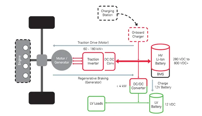
Buck converter : The Buck converter is used to step down the voltage. It is used to provide the Electronic control supply (12v) to sensors and Electronic control units.
Boost converter: The Boost converter is used to step up the voltage. It increases the voltage used to operate the motor when the Battery voltage decreases.
Buck-Boost converter: It is used to step and step down the voltage.
DC to AC converter: (Inverter)
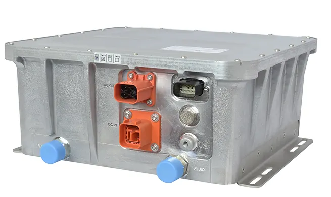
DC to AC converters are commonly known a Inverters. Inverters are used if the motor is 3 phase Induction motor. The DC to AC converters are used to control that motor by changing the voltage and frequency (V/f control).
AC to DC converter: (Rectifier)
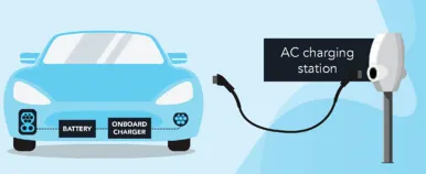
AC to DC converters are commonly known as rectifiers. The AC to DC converters are commonly used in adapters for charging. In Plug in Hybrid EVs and BEV, AC to DC converters are used to charge the battery from an external AC supply. The disadvantage of AC to DC converter is the limitation in charging speed.
2. To calculate the EV steady state speed for duty cycle of 70% with the given parameters
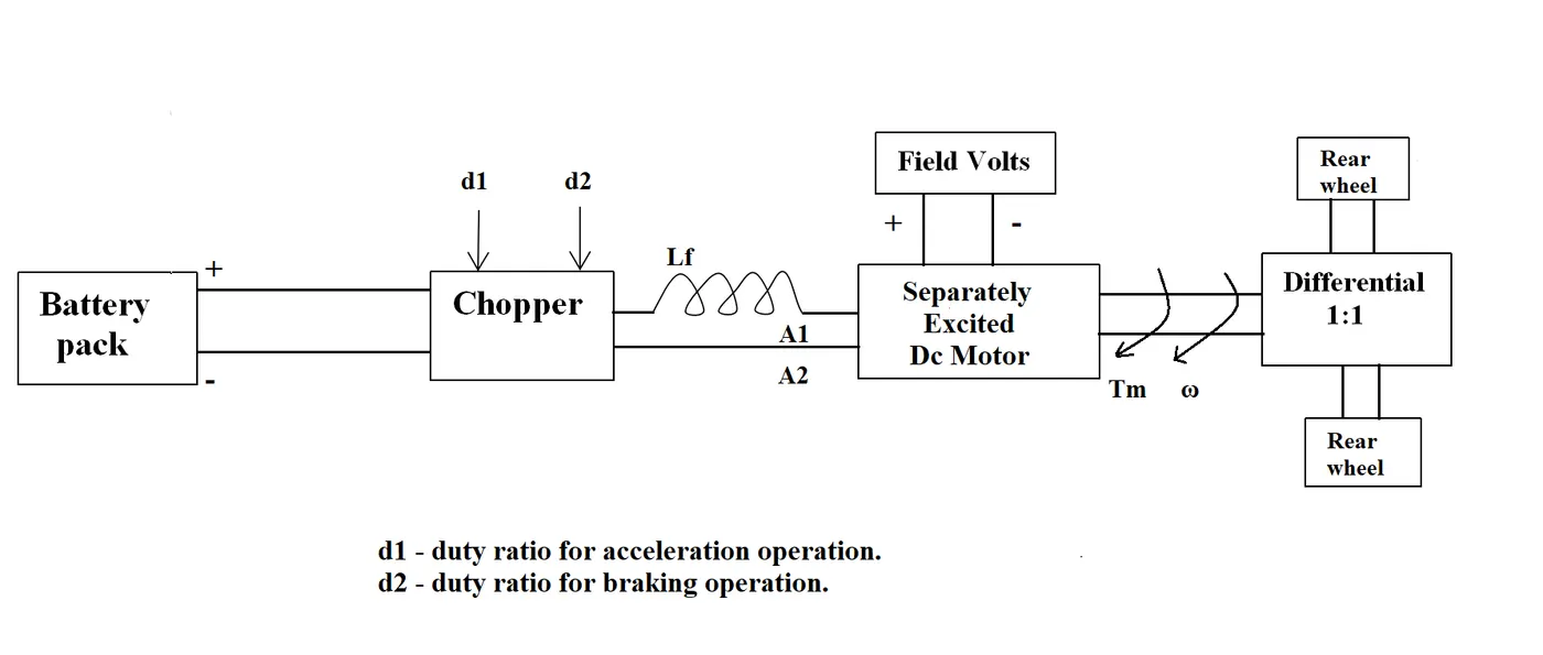
Given data:
Rated Armature voltage (Va) = 72 V
Rated armature current (Ia) = 400 A
Armature Resistance (Ra) = 0.5 Ω
KΦ= 0.7 Volt second
Chopper Switching frequency (f) = 400 Hz
Toque T = 24.7+ (0.0051) w²
Calculation:
For Duty Cycle, d = 70%
Voltage = Armature voltage * Duty cycle
= 72 x 0.7
= 50.4 V
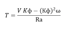
Substituting the given values,
Torque, T = ((50.4*0.7)- (0.7*0.7*ω))/0.5
= (35.28-0.49 ω)/0.5
T = 70.56 - 0.98 ω
Equating the above equation with the given Torque equation ( T = 24.7 + 0.0051 ω^2 )
70.56 - 0.98 ω = 24.7 + 0.0051 ω^2
0.0051 ω^2 + 0.98 ω - 45.86 = 0
Solving the above quadratic equation,
ω = 38.92 rad/sec ω = -231.02 rad/sec
The steady state speed of the given EV is 38.92 rad/sec
3.To Develop a mathematical model of a DC Motor for the below equation using Simulink.
Given equation:
ω = (V/Kφ)-((T*Ra)/(Kφ)^2))
ω--Angular velocity
V--Armature Voltage
T--Motor Torque
Ra--Armature Resistance
Kφ--Motor Constants
Simulink model:
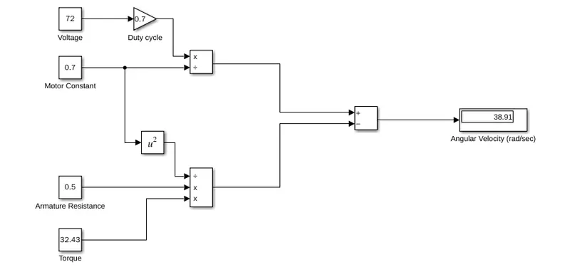
In the Simulink model Voltage, Motor constant, Armature resistance, Torque are input values with Constant blocks. Multiplier, Divide, Subtract, Square blocks are used for calculation. Angular velocity can be viewed in the Display block after simulation.
4. To explain about the blog of Induction motor vs Blushless DC motor by Wally Rippel .
Main Points:
* Wally Rippel mentioned that various types of Motors will be used similar to various types of Engines that we are using according to the personal requirements.
* Lead-acid batteries are replaced by Lithium-ion batteries.
* DC brush motors are replaced by DC Brushless or Induction Motors.
* Contactor Controllers are replaced by Modulating Inverters.
* The author discussed about DC Brushless Motor and Induction Motor with its features
of operation.
* Explained that the stators for the 3-phase induction motor and the DC brushless motor are identical with three sets of distributed winding. The rotor of DC brushless motor have permanent magnets and Induction rotor has short circuited conductors.
* Mentioned that DC brushless drives require an absolute position sensor, while induction drives require only a speed sensor.
* Explained rotor heat is less, good power factor with the DC brushless drive and limitation with increase in its size.
* Explained that the 3-phase induction motor has great utility but with several limitations.
* Compared the future trends which may occur in DC Brushless as well as in Induction motor.
* Concluded that DC brushless drives will likely continue to dominate in the hybrid and coming plug-in hybrid markets, and that induction drives will likely maintain dominance for the high-performance pure electrics.