Project-1: Powertrain for aircraft in runways
Powertrain for aircraft in runways
1. To list out the total weight of various types of aircrafts
The Empty weight, Maximum fuel weight, Maximum cargo weight, Maximum Gross Takeoff weight of various Aircrafts are Tabulated as follows
| Aircraft | Empty Weight | Max Fuel Weight | Max Cargo Weight | Max Gross Takeoff Weight |
|---|---|---|---|---|
| Anatanov AN - 225 | 285,000 kg | 300,000 kg | 190,000 kg | 640,000 kg |
| Airbus A380 - 800 | 277,000 kg | 254,000 kg | 84,000 kg | 575,000 kg |
| Boeing 747 - 800 | 220,100 kg | 194,000 kg | 134,000 kg | 447,700 kg |
| Airbus A340-500 | 168,000 kg | 175,000 kg | 54,000 kg | 372,000 kg |
| Boeing 777-300ER | 168,000 kg | 145,500 kg | 67,100 kg | 352,000 kg |
| Boeing 787-10 | 135,500 kg | 101,500 kg | 57,300 kg | 254,000 kg |
| Boeing 737-900 | 44,700 kg | 24,000 kg | 20,200 kg | 85,000 kg |
| Airbus A320- 100 | 42,600 kg | 22,100 kg | 20,000 kg | 68,000 kg |
| Embraer 190 | 28,800 kg | 13,000 kg | 13,100 kg | 48,000 kg |
| Gulfstream G650 | 24,500 kg | 21,900 kg | 3,000 kg | 45,200 kg |
| Bombardier CRJ900 | 21,850 kg | 8,900 kg | 2,760 kg | 36,500 kg |
| Bombardier Q400 | 17,800 kg | 5,300 kg | 8,500 kg | 28,000 kg |
| Learjet 75 | 6,300 kg | 2,750 kg | 1,300 kg | 9,700 kg |
| Cessna 206H | 990 kg | 235 kg | 520 kg | 1,630 kg |
| Sirrus SR22 | 1,000 kg | 220 kg | 430 kg | 1,630 kg |
| Cessna 172R | 770 kg | 170 kg | 255 kg | 1,100 kg |
2. To compare the difference between ground speed and air speed of an Aircraft
Wind Speed :
The wind speed is a vector quantity and has both a magnitude and a direction and the direction also plays a significant roles. Consider a reference point on the ground, the air moves relative to the reference point at the wind speed. In the figure, only velocities along the path of Aircraft are considered. A positive velocity is defined in the direction of motion of Aircraft. The crosswinds are neglected which occur perpendicular to the flight path.
Air speed:
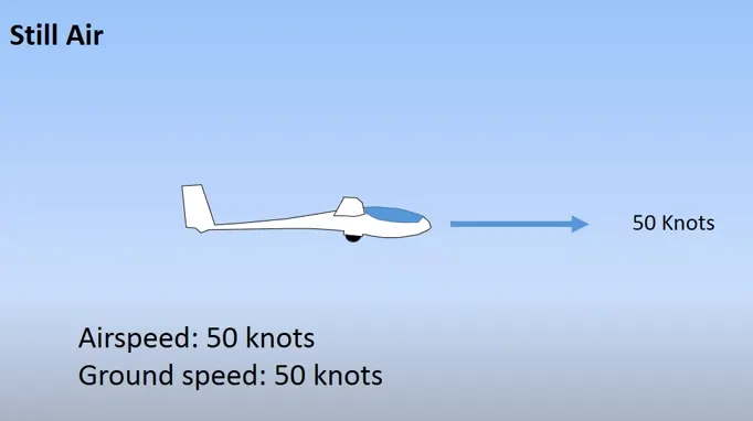
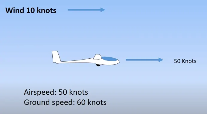
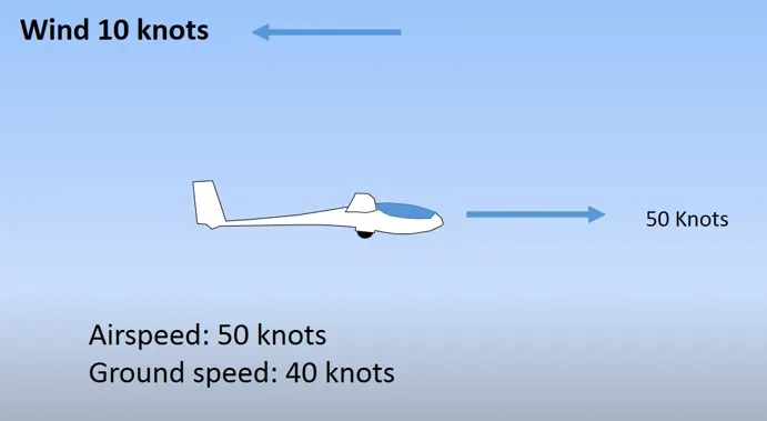
Air speed is the speed of the aircraft as it moves through the air. The air speed will be shown in air speed indicator of an aircraft. Airspeed cannot be directly measured from a ground position but must be computed from the ground speed and the wind speed. Airspeed is the vector difference between ground speed and wind speed. On a perfectly still day, the airspeed is equal to the ground speed. But if the wind is blowing in the same direction that the aircraft is moving, the airspeed will be less than the ground speed.
Ground Speed:
Ground speed is the speed of the Aircraft over the ground. It depends on the Wind strength, Direction and Airspeed.
Still Air:
Air Speed = Ground Speed
Wind speed along the direction of Aircraft:
Air Speed = Ground Speed + Wind Speed
Wind speed opposite to the Aircraft:
Air Speed = Ground Speed + Wind Speed
3. It is not recommended to use aircraft engine power to move it on the ground at Airport.
Taxiing is the movement of an aircraft on the ground by using its own power. The aircraft usually moves on its wheels by using only the engine power.
It is not recommended to use aircraft engine power to move it on the ground at Airport because there are chances of Unintended movement of the Aircraft during engine running.
* During the running of high power engine, loss of control can happen and this can damage the aircraft itself or other nearby aircrafts.
* There is a risk of injury to ground support personnel who may be in relatively close proximity to the aircraft
* It is easier for truck driver to see the surroundings better than the pilot sitting in the cockpit with limited window. The pushback driver knows the airport better than the pilot.
* It also saves fuel. virgin Atlantic had proposed a new system in which pushback truck will move the aircraft all the way to runway to save fuel and reduce impact of environment.
* The plane engines are very loud. When more than one plane will add up their sound, than it will not be pleasant for passengers and others near airport
4. To move the Aircraft to the runway when it is ready to take off.
Although many aircrafts are capable of moving in backward using reverse thrust, as result the jet blast or prop wash can cause damage to the terminal building or equipment. Engine close to ground may also blow sand and debris forward and then suck them into the engine, causing damage to the engine. Therefore for moving the aircraft, pushback trucks in the airport. A pushback truck lifts the front wheel of the aircraft, their role in most airports is to move the aircraft away from the parking spot on to the taxiways, which is called towing.
Towing is a method of moving the aircraft, using the power of a specialized ground vehicle attached to the nose landing gear. Towing can be used for the movement of Aircrafts in service and out of service. The specialized ground vehicle used to move the aircraft is known as Tow Tractor.
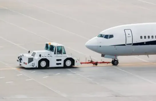
Towing aircraft can be a hazardous operation and can cause damage to the aircraft and injury to personnel if towing is carried out recklessly. The specific instructions for each model of aircraft are detailed in the maintenance instructions and are to be followed in all instances. Before the aircraft to be towed, a qualified person must be in the flight deck to operate the brakes if the tow bar fails or unhooked. The aircraft can then be stopped to prevent possible damage.
The types of tow bars available for general use can be used for many types of towing operations. These bars are designed with sufficient tensile strength to pull most aircraft, but are not intended to be subjected to torsional or twisting loads. When the bar is attached to the aircraft, inspect all the engaging devices for damage or malfunction before moving the aircraft. When towing the aircraft, the towing vehicle speed must be reasonable, and all persons involved in the operation must be alert. When the aircraft is stopped, do not rely upon the brakes of the towing vehicle alone to stop the aircraft. The person in the flight deck must coordinate the use of the aircraft brakes with those of the towing vehicle.
The attachment of the tow bar varies on different types of aircraft. Aircraft equipped with tail wheels are generally towed forward by attaching the tow bar to the main landing gear. In most cases, it is permissible to tow the aircraft in reverse by attaching the tow bar to the tail wheel axle. Any time an aircraft equipped with a tail wheel is towed, the tail wheel must be unlocked or the tail wheel locking mechanism may damage or break. Aircraft equipped with tricycle landing gear are generally towed forward by attaching a tow bar to the axle of the nose wheel. They may also be towed forward or backward by attaching a towing bridle or specially designed towing bar to the towing lugs on the main landing gear. When an aircraft is towed in this manner, a steering bar is attached to the nose wheel to steer the aircraft
5. To Learn about take off power, tire design, rolling resistance, tire pressure, brake forces when landing
Takeoff power:
Takeoff is the phase of flight in which an aerospace vehicle leaves the ground and becomes airborne. For aircraft that take off horizontally, this usually involves starting with a transition from moving along the ground on a run way.
When a plane is moving on the ground, the forces acting on it are the gravity, thrust and the drag. The lift is also acting, but as the plane is on the ground, the lift force is obviously less than gravity. In order to take off, the amount of thrust with be required speed of the plane results in generation of lift force. This thrust force and the speed gives the power product. It has to overcome the gravity by generating lift and drag by generating thrust. This is how an aircraft take off takes place.
Tire Design:
An aircraft tire is designed to withstand extremely heavy loads for short durations. The number of tires required for aircraft increases with the weight of the aircraft, as the weight of the airplane needs to be distributed more evenly. Aircraft tire tread patterns are designed to facilitate stability in high crosswind conditions, to channel water away to prevent hydroplaning, and for braking effect.
Aircraft tires also include fusible plugs, designed to melt at a certain temperature. Tires often overheat if maximum braking is applied during an aborted takeoff or an emergency landing. The fuses provide a safer failure mode that prevents tire explosions by deflating in a controlled manner, to reduce the damage to aircraft and objects in the surrounding environment.
Retreading: Retreading is methods of restoring a worn tire by renewing the tread area or by renewing the tread are a plus one or both sidewalls. Repairs are included in the tire retreading process.
Load Rating: Load rating is the maximum permissible load at a specified inflation pressure.
Ply Rating: Ply Rating is used to identify the maximum recommended load rating and inflation pressure for a specified tire. It is an index of tire strength.
Speed Rating: The speed rating is the maximum takeoff speed to which the tire has been tested.
Skid Depth: Skid depth is the distance between the tread surface and the deepest groove as measured.
Aircraft tires :
* Most of the aircrafts have radial tire. Bias is an older design, and it is mainly used for road vehicles. Radial tires have the word RADIAL on the sidewall. Radial tires are more expensive than bias-ply tyres, Radial tires are in demand because of their lower life cycle cost and long term value.
* Aircraft tires are conductive. Aircraft tires are manufactured with tread rubber with conducting compounds to permit earthing of static charges. In early days when tires were not sufficiently conductive, aircraft used to have a conductive strip hanging down from the axle of the landing gear. Upon landing, this strip would be the first part of the aircraft to touch the earth. This discharges any static electricity accumulated on the outer surfaces of the aircraft.
* Chines are also called deflectors. Chine tire used on the nose wheel of aircraft, specially fuselage-mounted jet engines. It diverts runway water away from the engine inlets. Chines are molded into the sidewall of nose tires that deflect water sideways to help reduce excess water ingestion into the engines. Tires may have chines on one or both sides, depending on the number of nose tires on the aircraft.
Tyre construction:
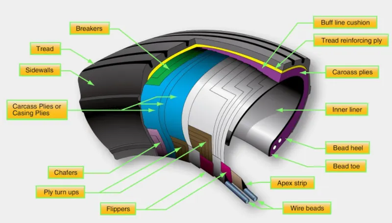
Tread: The tread is made of rubber mixed with other additives to obtain the desired level of toughness, durability, and resistance to wear. The tread pattern is designed to aircraft operational requirements, with the ribbed tread design used widely due to its good traction under varying runway conditions.
Sidewall: The sidewall is a protective layer of rubber that covers the outer casing ply. It extends from the tread edge to the bead area.
Tread Reinforcing Ply: One or more layers of fabric that strengthens and stabilizes the tread area for high-speed operation. It also serves as a reference for the buffing process when tires are retreated.
Buff Line Cushion: The buff line cushion is made of rubber compound to enhance the adhesion between the tread reinforcing ply and the breakers or casing plies. It is of sufficient thickness to allow for the removal of the old tread when the tire is retreated.
Breakers: Breakers are reinforcing plies of rubber-coated fabric placed under the buff line cushion to protect casing plies and strengthen and stabilize the tread area. They are considered an integral part of the casing construction.
Caring Plies: Alternate layers of rubber-coated fabric (running at opposite angles to one another) provide the strength of the tire.
Wire Beads: Hoops of high tensile strength steel wire that anchor the casing plies and provide a firm mounting surface on the wheel. The outer edge of the bead that fits against the wheel flange is called the bead heel. The inner bead edge is called the bead toe.
Apex Strip: A wedge of rubber affixed to the top of the bead bundle.
Flippers: Layers of rubberized fabric that help anchor the bead wires to the casing and improve the durability of the tire.
Ply Turnips: The casing plies are anchored by wrapping them around the wire beads toform ply turnips.
Chafer: A protective layer of rubber and/or fabric located between the casing plies and wheel to minimize the damages during fitting or removal operations.
Liner: In tubeless tires, the liner is a layer of low permeability rubber that acts as a built-in tube and restricts gas from diffusing into the casing plies in tube-type tires, a thinner liner is used to prevent tube chafing against the inside ply
Racial tyre: They have fewer components in their construction and are lighter than similarly sized bias-ply tires. Components that differ from bias-ply construction as follows:
Overlay: A layer of reinforcing rubber-coated fabric placed on top of the belts to aid in high-speed operation. Belt: Plies: A composite structure that stiffens the tread area for increased landings. The belt plies increase the tire strength in the tread area.
Casing Plies: As in bias-ply tires, the casing plies are layers of rubber-coated fabric. However, unlike those in bias plies that run at opposite angles to one another, radial plies run radially from bead to bead.
Chippers: The chippers are layers of rubber-coated fabric applied at diagonal angles that improve the durability of the tire in the bead area.
Rolling Resistance:
Rolling resistance is the force resisting the motion when a body rolls on a surface. It is mainly caused by non-elastic effects that is, not all the energy needed for deformation of the wheel, roadbed. Rolling resistance is recovered when the pressure is removed. Two forms of this are hysteresis losses and permanent deformation of the object or the surface. The slippage between the wheel and the surface also results in energy dissipation.
Rolling Resistance Force Frr = urr * m * g
urr - Co efficient of rolling resistance
m - Total mass of the aircraft
g - gravitational constant = 9.8 m/s^2
This coefficient of rolling resistance is generally much smaller than the coefficient of sliding friction. Any coasting wheeled vehicle will gradually slow down due to rolling resistance including that of the bearings, but a train car with steel wheels running on steel rails will roll farther than a bus of the same mass with rubber tires running on tarmac. Factors that contribute to rolling resistance are the deformation of the wheels, the deformation of the roadbed surface, and movement below the surface. Additional contributing factors include wheel diameter, load on wheel, surface adhesion, sliding, and relative micro-sliding between the surfaces of contact. The losses due to hysteresis also depend strongly on the material properties of the wheel or tire and the surface.
Breaking Forces:
A short landing run requirement for an aircraft is important from economic, operational and strategic considerations. Too strong a braking produces skid, which is an undesirable condition, while weak breaking results in a long landing run. The shortest possible landing run without any skidding requires a variable braking force to match the frictional force at all times.
In Aeronautics, air brakes or speed brakes are a type of flight control surfaces used on an aircraft to increase drag or increase the angle of approach during landing. Air brakes differ from spoilers in that air brakes are designed to increase drag while making little change to lift, whereas spoilers reduce the lift-to-drag-ratio and require a higher angle of attack to maintain lift, resulting in a higher stall speed.
6. A. With necessary assumptions, calculate the force and power required to push / pull an aircraft by a towing vehicle.
Assume
Total mass m = Towing vehicle mass + Aircraft mass
m = 40000 + 100000 = 140000
μrr = 0.04
ρ = 1.25
Cd = 0.05
A = 25 m^2
v = 3 m/s
Formula used:
Rolling Resistance Force (Frr) =μrr *m*g
μrr - co-efficient of Rolling resistance
m - Total mass (kg)
g - Acceleration due to Gravity (m/s^2)
Frr = 0.04 * 140000 * 9.8
= 54880 kN
Air Drag Force (Fad) = 0.5*ρ*A*Cd*v^2
ρ - Air Density (kg/m^3)
A - Frontal Area (m^2) A = Width * Height
Cd - Drag co-efficient
v - velocity (m/s)
Fad = 0.5 * 1.25 * 25 * 0.05 * 3 * 3
= 7.031 N
Total force = Frr + Fad
= 54880 + 7.031
Total force = 54890 N
Total power = Total force * velocity
= 54890 * 3
Total power = 164670 W = 164.67 kW
6.B. To Develope the model for the calculated force and power using Simulink.
Simulink model:
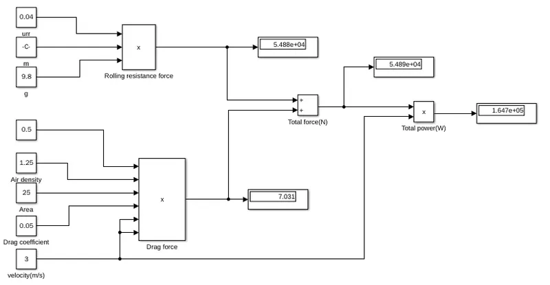
From the Simulink model, the total power required to required for the towing vehicle is calculated using the total tractive force and the velocity. The total tractive force is calculated from the Drag force and the rolling resistance force. Assuming the total mass of the vehicle is 140000 kg, rolling resistance coefficient is 0.04, frontal area is 25 m^2, Drag coefficient is 0.05, velocity is 3 m/s.
7.A. To Design an electric powertrain with type of motor, power rating, and energy requirement to fulfill aircraft towing application in Simulink and to Estimate the duty cycle range to control the aircraft speed from zero to highest.
Block Diagram:
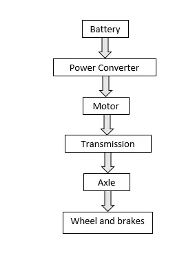
To design an electric powertrain, the ratings are to be calculated for the following blocks
* Motor
* Power converter
* Battery capacity
Motor:
Torque on the wheel = Total force * Tire radius
considering the Tire radius = 0.8 m
Torque on wheels = 164670 * 0.8 = 13176 Nm
considering gear ratio = 10, Transmission efficiency = 85%
Required Motor Torque = Wheel Torque / (Gear ratio * Transmission efficiency)
=131736/(10 * 0.85)
= 15498.4 Nm
Motor Torque = 15.5 kNm
considering motor losses (Copper loss, Iron loss, Windage loss)
Motor Efficiency = 90%
Required Motor Power = 15498 *0.9
=13948 W
Motor Power = 13.95 kW
Power converter:
The required power = 13.95 kW , Rated power of Motor = 15 kW
Duty cycle = Required power / Rated power
= 13.95/15
= 0.93
The controller can be operated with 0 to 93 % of duty cycle
Battery capacity:
Assuming Towing time = 10 minutes = 0.167 hours
Required Battery capacity = Required power * Time
= 13950 * 0.167
= 2329 wh
Required Battery capacity =2329 Wh
The battery of standard 2.5Kwh can be used for the towing vehicle.
Simulink model:
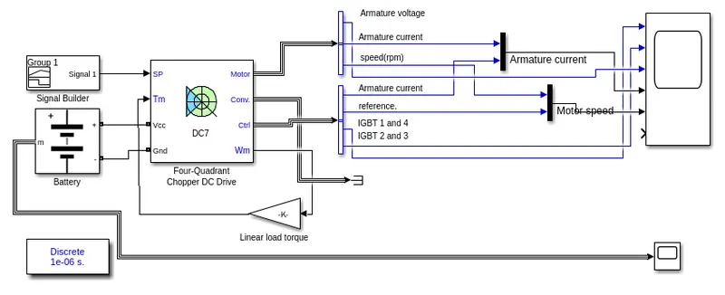
The Simulink model is developed for the Towing vehicle with the obtained Battery capacity using DC7 which is also known as Four Quadrant chopper DC Drive. The Major blocks of the Simulink model are Signal builder, DC 7 Drive, Battery block.
Signal Builder:
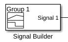
The input step signal is generated using the signal builder. It is used to provide the input signal to the DC7 drive. 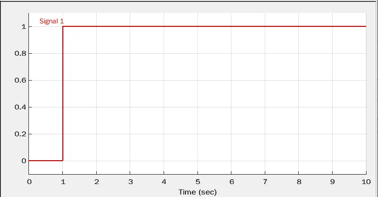
Battery:
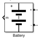
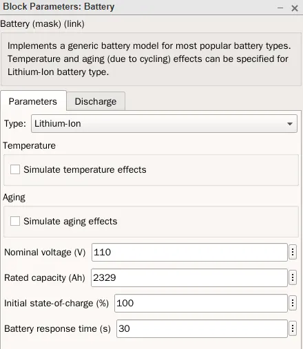
The battery rating is modified from the calculated battery capacity of the Towing vehicle and the battery voltage was assumed to be 110 volts. The output from the positive terminal of the battery is connected to the Vcc terminal and the negative terminal is connected to the Gnd of the DC7 drive.
DC7 Drive:
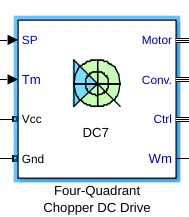
The Motor, Converter outputs are obtained from the DC7 drive. The signal builder is connected to the SP port of the drive to give the vehicle movement pulse. The battery with the modified value is connected to the Vcc and Gnd ports of the DC7 drive.
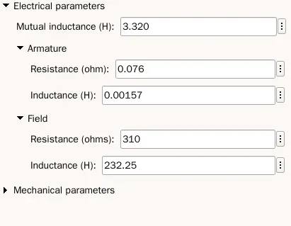
Output:
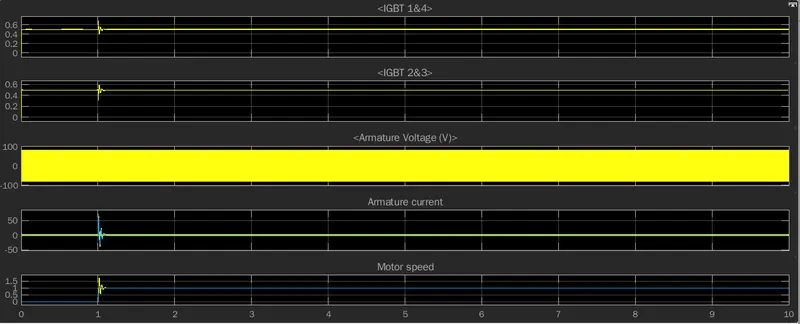
From the output values of Motor speed, Armature current, Armature voltage, Duty cycle of IGBT 1 and 4, IGBT 2 and 3. The required output is obtained for the corresponding change in the input from the signal builder. When the input from the signal builder is high, the armature current increases to achieve the rated speed. The speed of the motor becomes steady and continues in the same speed.
Assumed parameters:
The parameters that are taken in to assumptions to calculate the required Torque, required Motor power, Battery capacity, converter duty cycle.
| Parameters | Values | unit |
| Mass of Towing vehicle | 40000 | kg |
| Mass of Aircraft | 100000 | kg |
| Frontal area | 25 | - |
| Coefficient of rolling resistance | 0.04 | - |
| Drag coefficient | 0.05 | - |
| Velocity of vehicle | 3 | m/s |
| Tire radius for Towing vehicle | 0.8 | m |
| Gear ratio | 10 | - |
| Transmission Efficiency | 85 | % |
| Motor Efficiency | 90 | % |
| Towing time | 10 | minutes |
7.B. To design the parmeters in the excel sheet
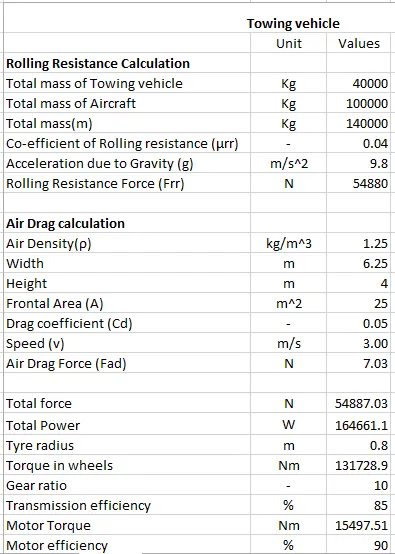
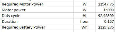
The values of required Motor power, Dutycycle, Battery capacity of a Towing vehicle is calculated from the Rolling resistance force, Airdrag force, Torque on the wheels, Gear ratio, Efficiency. The corresponding excel sheet is also attached as a file.