Week-7 Challenge: DC Motor Control
1. A. Explain a MATLAB demo model named ‘Speed control of a DC motor using BJT H-bridge’.
B. Comment on the armature current shoot-up from the scope results.
C. Refer to the help section of ‘The Four-Quadrant Chopper DC Drive (DC7) block’. Compare it with the H-bridge
Ans:-
A]Explaination
as go to the help document and open model"Speed control of a DC motor using BJT H-bridge’."
components:-
1.DC Voltage source
2.IGBT Switch
3.Diode
4.DC Machine(5HP ,240V,1750 RPM 300V FIELD)
5.DC voltage 300v
6.500 HZ PULSE GENERATOR
7.Switch
8.Armature voltage control
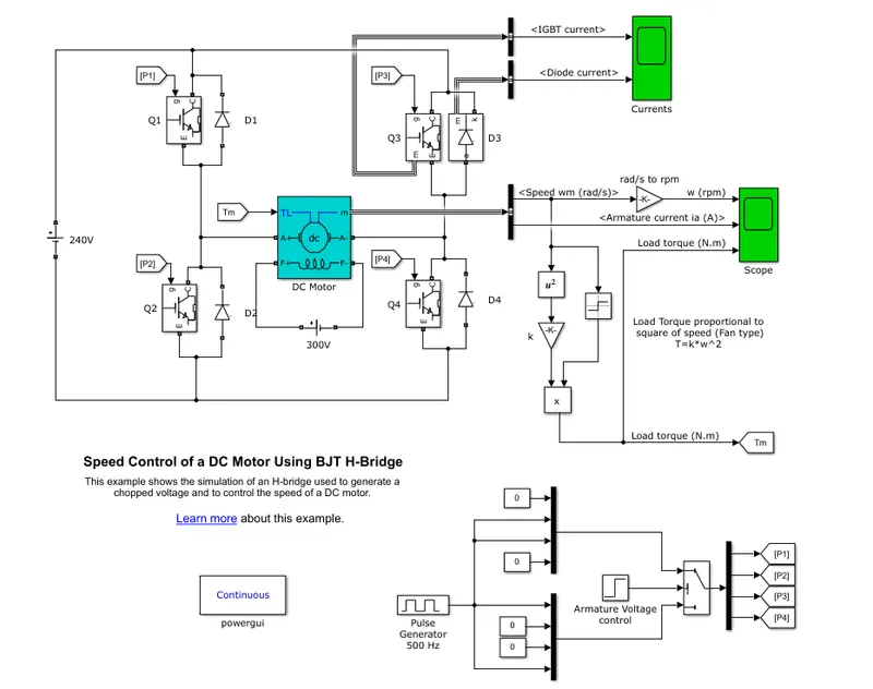
IBGT:-insulated gate bipolar transistor, as when the BJT work in to the power switching applications it works as IGBTas compare to the mosfet it has high power loading capacity but low switching frequency it has an 3 terminals as(G-gate or control terminal,E-Emmiiter,C-Collector terminal) as compare to the BJT IGBT is good (BJT operated in saturation mode) as a forward voltage Vf is devloped collector and emmiter current flowing device control nit by field control So IGBT block used model the bjt deviceworking of H-Bridge: as the pair of the IGBT with Diode as 1 pair of diode+IGBT are for the forward running and other pair is used for the rearward running. consider motor run in positive direction so at that time
forward:- +ve supply - Q1 - A+ - (-A) - Q4 - (-ve supply) as well d2 and d3 are work as freewheeling diodes
rearward:- +ve supply - Q3 - A+ - (-A) - Q2 - (-ve supply) as well d1 and d4 are work as freewheeling diodes
As shown belows:-
B] armature current and shoot up:-
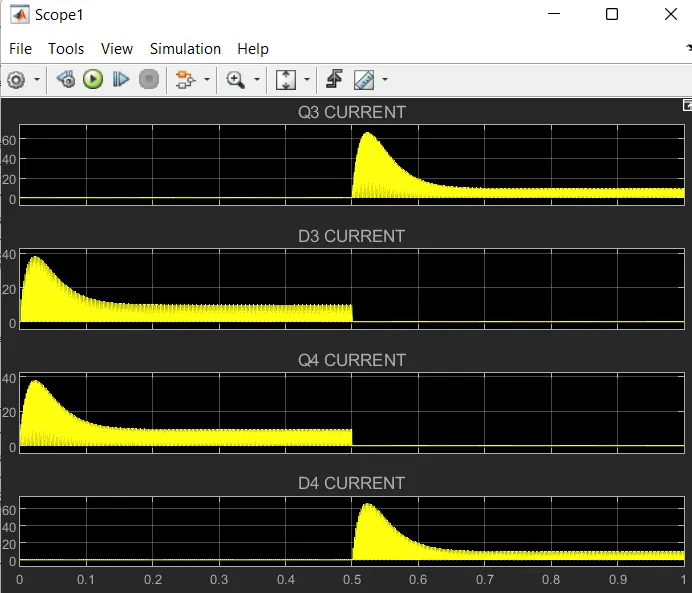
Gate pulse:- gate input are given by the pulse generator if the armature voltage is more than 0.5
so by it we get an outputs from motor as the speed,armature current , Load Torque in(NM)
as due to the duty cycle as run the model and we obtained the results as belows
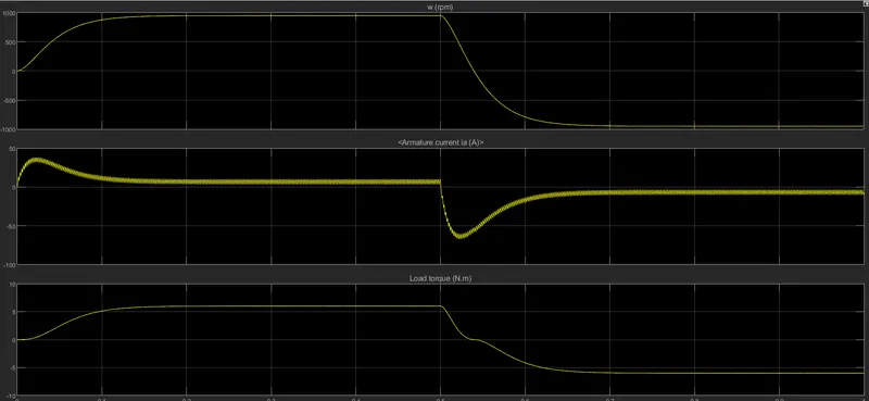
1. case 1:- as the motor runs in positive direction with an the duty cycle of 75% as 230v - 75%=180v at time 0.5sec
consider as the motor runs in nagetive direction as the output is follow as
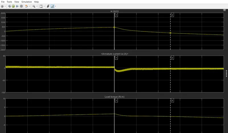
2. case 2:- as the motor runs in positive direction with an the duty cycle of 50% as 230v - 50%=115v at time 0.5sec
consider as the motor runs in nagetive direction as the output is follow as
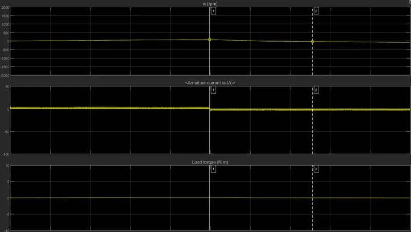
case 3:- as the motor runs in positive direction with an the duty cycle of 25% as 230v - 25%=57.5v at time 0.5sec
consider as the motor runs in nagetive direction as the output is follow as
so as from the 3 cases we get an the speed, torque and armature current characherstics as belows.
- case 1:-plot as we see that current has to be flow initially at an staring is very high and then in nagetive cycle it goes to the reversal motor direction with an very smoothly
- as compare to the 3 plots we conclude that the duty cycle reduces as the motor current of armature is also reduces only diffrence is that the load tourque also reduces is the disadvantages
- as well as the shoot up happense due to the switching action in circuit causes an the heat loss during an the switching this loss we cant avoid but to protect the convertoer we used device called as an the heat sink device.
C] C. Refer to the help section of ‘The Four-Quadrant Chopper DC Drive (DC7) block’. Compare it with the H-bridge
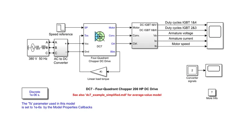
AS the above is DC7 4 quadrant chopper
objective:- we have to know the diffrence between the 4Quadrant chopper and H-Bridge
The 200 HP DC motor is separately excited with a constant 150 V DC field voltage source. The armature voltage is provided by an IGBT converter controlled by two PI regulators. The converter is fed by a 515 V DC bus obtained by rectification of a 380 V AC 50 Hz voltage source. In order to limit the DC bus voltage during dynamic braking mode, a braking chopper has been added between the diode rectifier and the DC7 block.
The first regulator is a speed regulator, followed by a current regulator. The speed regulator outputs the armature current reference (in p.u.) used by the current controller in order to obtain the electromagnetic torque needed to reach the desired speed. The speed reference change rate follows acceleration and deceleration ramps in order to avoid sudden reference changes that could cause armature over-current and destabilize the system. The current regulator controls the armature current by computing the appropriate duty ratios of the 5 kHz pulses of the four IGBT devices (Pulse Width Modulation). For proper system behaviour, the instantaneous pulse values of IGBT devices 1 and 4 are opposite to those of IGBT devices 2 and 3. This generates the average armature voltage needed to obtain the desired armature current. In order to limit the amplitude of the current oscillations, a smoothing inductance is placed in series with the armature circuit
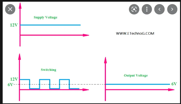
chopper circuit:- as the dc chopper circuit is nothing but converts an input fixed voltage /power to variable voltage/power
the 200hp dc motor is saperat excited dc motor with constant 150v of field voltage source the arature voltage is provided by an igbt convertor controlled by 2 pi regulator by a 515 v dc bus obtain by an rectification of 380v ac 50hz voltage sourcein order to dc bus voltage during an dynamic braking ,a braking chopper added between an the diode rectifier and dc7 block
the first regulator is an speed regulator follow by a current regulator output the armature current reference in pu using an current control in order to obtain electromagnetic torque need to reach the desired speed .the speed referance change rate follows an acceleration and declaration ramps in order to sudden referance change that could cause armature over current and destabilize the system.the control regulator controls the armature current by computing the appropriate duty ratio of 5khz pulses of four igbt for an proper system behavior instanteneous pulse value of igbt 1 and 4 are the opposite to those 2 and 3 generates an the average armature voltage needed to obtain an armature current oscillations a smoothing inductance placed in circuits in series.
H-Bridge
it is an simple forward and reverse ckt that makes the motor rotateas in firward and rearward
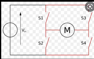
forward:-AS if we close an the s1 and s4 then the motor rotates in forward direction so motor start an spinning into clockwise direction
rearward:-if the s3 and s2 are connected so the motor start rotating in antickwise direction
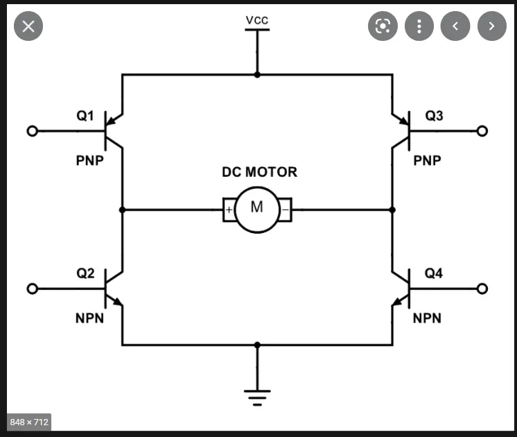
circuit diagram of H-Bridge
as from the 2 ckt as we know that what is actually diffrence in construction so the diffrence also is in the working diffrence is also there as the
Q2Develop a 2-quadrant chopper using simulink & explain the working of the same with the relevant results. (Refer to article - Multiquadrant operation of motor )
THE TWO QUADRANT CHOPPPER dc drive (DC6)block re[resents an the dc-dc pwm convertor drive for dc motors feature as an closed loop speed control within the 2 quadrant operations the speed control loop outputs the referance armature current of the machine using an pi controller the chopper duty cycle corresponded to armature duty cycle is compared with the sawtooth carrier to obtain the requirment pwm signals for an chopper
the main dvantages od this drive is as simplicity as it operates in only 2 quadrants forward motoring and reverse generating in order with an the high switching frequency of switching a lower armatuure currents (compare with the thyristored based dc drives )as the reversible and regenrative braking mode are in important operations
ity as it operates in only 2 quadrants forward motoring and reverse generating in order with an the high switching frequency of switching a lower armatuure currents (compare with the thyristored based dc drives )as the reversible and regenrative braking mode are in important operations
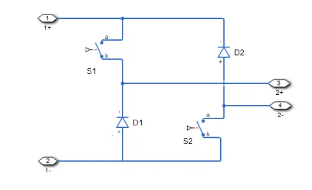
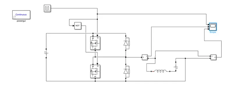
- so as an the input voltage is given as an the dc source voltage as an input through the pulse genearator kept at an the 32
- for an the power switches or an transistor we will be used the MOSFET or FET couple with an the diodes in parallel as 2 pair of switch and diode such connected as an 2 quadrant operation as the running and the braking or reverse running
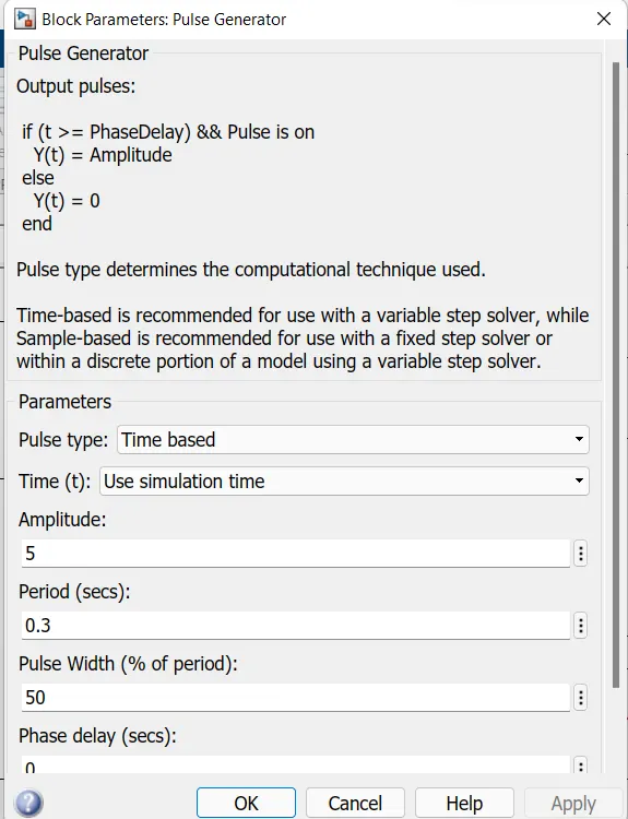
- now consider as the pulse generator with an the 50%duty cycle ,0.3 sec and 5 is amplitude the output of these are connected to the switch 1 and switch 2 by the not as to avoid the on the switch start at one time as these are connected to the gate of switch to trigger
- inductor is provide for an the when the switch 1 is off at thats time inductor stored an the currents as an the 50% means of an the 16v
- tomeasure or annalyse an the parameter we have another block which is called as the switch
- powergui is block simulate any simulink model as specialized power system
Working:-
- in the two quadrant choppper average voltage is +ve but current is +ve or -ve as the 2 switches as an the sw1 and sw2 not start at same time othersiebmotor should be an hortcircuted avoid.
- when an the mosfet 1 is on so direction is mosfet- inductor and voltage source as the motor and then the reuurn path. when the pulses are off then at that time
- when sw 1 is offf codition Fd starts conducting and output voltage will be equal to v the direction of load current will be reverses since the inductor now discharge itself
- for an the regenerative braking ,the load will nagetive when ch2 is on the current completes an path from mosfet 2 to ive load terminal of load diode of the diode 2
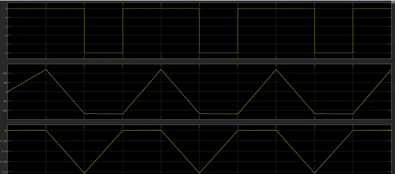
so the output as above form the diagrame1. pulse generator ,2 armature current,3.motor voltage input
Q3.Explain in a brief about operation of BLDC motor.
What is Brushless DC motor?
Brushless DC electric motors also known as electronically commutated motors (ECMs, EC motors).
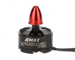
Primary efficiency is a most importent feature for BLDC motors. Because the rotor is the sole bearer of the magnets and it doesn't require any power. i.e. no connections, no commutator and no brushes. In place of these, the motor employs control circuitry. To detect where the rotor is at certain times, BLDC motors employ along with controllers, rotary encoders or a Hall sensor.
Construction of Brushless DC motor
In this motor, the permanent magnets attach to the rotor. The current-carrying conductors or armature windings are located on the stator. They use electrical commutation to convert electrical energy into mechanical energy.
The main design difference between a brushed and brushless motors is the replacement of mechanical commutator with an electric switch circuit. A BLDC Motor is a type of synchronous motor in the sense that the magnetic field generated by the stator and the rotor revolve at the same frequency.
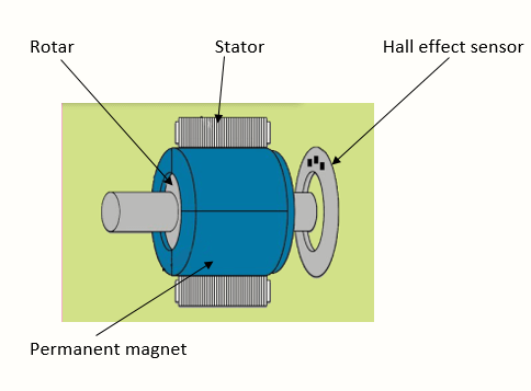
Brushless motor does not have any current carrying commutators. The field inside a brushless motor is switched through an amplifier which is triggered by the commutating device like an optical encoder.
The layout of a DC brushless motor can vary depending on whether it is in “Out runner” style or “Inrunner” style.
-
Outrunner – The field magnet is a drum rotor which rotates around the stator. This style is preferred for applications that require high torque and where high rpm isn’t a requirement.
-
In runner – The stator is a fixed drum in which the field magnet rotates. This motor is known for producing less torque than the out runner style, but is capable of spinning at very high rpm.
Working Principle of Brushless DC motor
BLDC motor works on the principle similar to that of a Brushed DC motor. The Lorentz force law which states that whenever a current carrying conductor placed in a magnetic field it experiences a force. As a consequence of reaction force, the magnet will experience an equal and opposite force. In the BLDC motor, the current carrying conductor is stationary and the permanent magnet is moving.
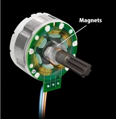
When the stator coils get a supply from source, it becomes electromagnet and starts producing the uniform field in the air gap. Though the source of supply is DC, switching makes to generate an AC voltage waveform with trapezoidal shape. Due to the force of interaction between electromagnet stator and permanent magnet rotor, the rotor continues to rotate.
With the switching of windings as High and Low signals, corresponding winding energized as North and South poles. The permanent magnet rotor with North and South poles align with stator poles which causes the motor to rotate.
Advantages of Brushless DC motor
- Less overall maintenance due to absence of brushes
- Reduced size with far superior thermal characteristics
- Higher speed range and lower electric noise generation.
- It has no mechanical commutator and associated problems
- High efficiency and high output power to size ratio due to the use of permanent magnet rotor
- High speed of operation even in loaded and unloaded conditions due to the absence of brushes that limits the speed
- Smaller motor geometry and lighter in weight than both brushed type DC and induction AC motors.
- Long life as no inspection and maintenance is required for commutator system
- Higher dynamic response due to low inertia and carrying windings in the stator
- Less electromagnetic interference
- Low noise due to absence of brushes
Limitations of Brushless DC motor
- These motors are costly
- Electronic controller required control this motor is expensive
- Requires complex drive circuitry
- Need of additional sensors
Applications of Brushless DC motor
Brushless DC motors (BLDC) use for a wide variety of application requirements such as varying loads, constant loads and positioning applications in the fields of industrial control, automotive, aviation, automation systems, health care equipments etc.
- Computer hard drives and DVD/CD players
- Electric vehicles, hybrid vehicles, and electric bicycles
- Industrial robots, CNC machine tools, and simple belt driven systems
- Washing machines, compressors and dryers
- Fans, pumps and blowers.