Project
Aim: to perform an the Simulation on BAJA ATV with continuously variable transmission and annalyse the result by changing an input as throttle and brake.
DISCRIPTION:
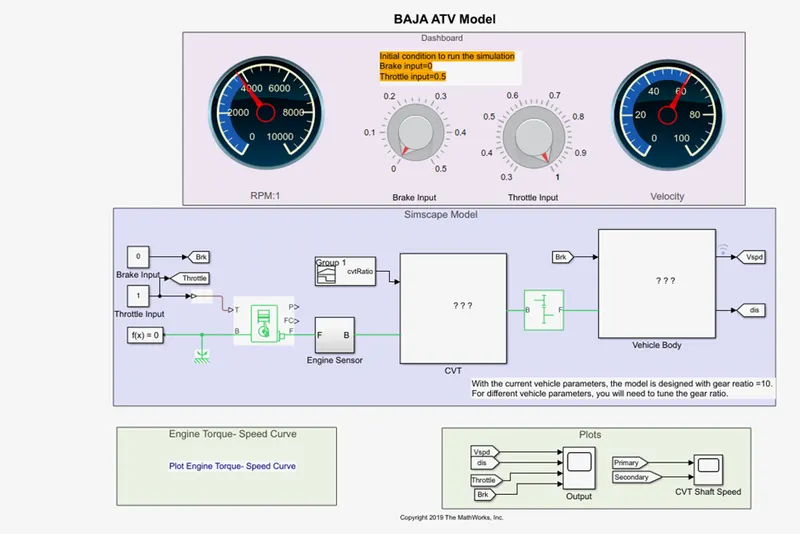
As per the question we have an the model as belows;
A].CVT Model:-
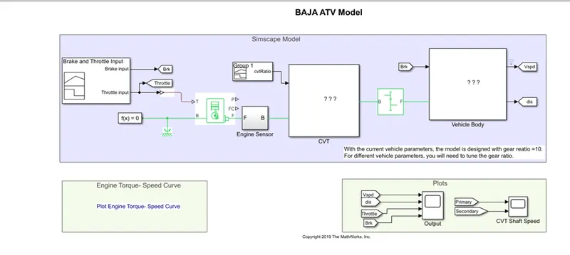
So it is an basically simple all-tarrain vehicle it contain following components as below
- Components
- Vehical model
Effect of change in brake and throttle.
a.Components:-
1.generic engine
2.CVT
3.vehicle body
4.engine sensor
5.simple gear
1.Generic engine:
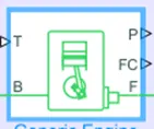
Generic engine: diesel engines suitable for use at initial stages of modeling when only the basic parameters are available. Optional idle speed and red line controllers are included.The throttle input signal T lies between zero and one and specifies the torque demanded from the engine as a fraction of the maximum possible torque. If the engine speed falls below the Stall speed, the engine torque is blended to zero. If the engine speed exceeds the Maximum speed, the simulation stops and issues an error message. Connections F and B are mechanical rotational conserving ports associated with the engine crankshaft and engine block, respectively. Connections P and FC are physical signal output ports through which engine power and fuel consumption rate are reported.F -follower ,B-base,P-engine power ,Fc-fuel consumption , T-throttle
2.CVT(Continuous Variable Transmission); its just as simple 2 pully mechanism in which convert to the speed and torque as motion. . When primery pully get inwords then secondary pully get outvward that time speed overdrive happened.
for 1st condition Rs> Rp- Speed reduction.
for 2nd condition Rp> Rs- overdrive it contains as following
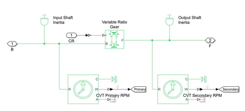
- Variable gear ratio:- it is just transferring an engine speed rpm to the vehicle base and follower
- Inertia:-it is just an physical mechanical rotational inertia
- Ideal Rotational Motion Sensor:- these are nothing but an the only sensor
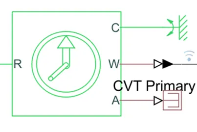
R-referance as an the input
C-common as rotating referance
W-angular velocity
A-angle
- Variable Ratio Gear:-its just simple gear ratio input to output and R is that input so by taking an input from the ideal motion rotational sensor of cvt primary and that’s output gives to the secondary cvt its just an simple variable gear ratio.
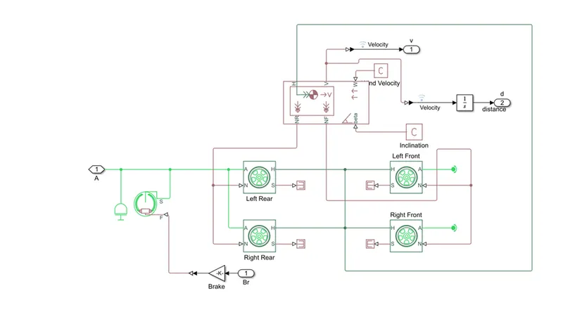
3.Vehicle Body:-its simple vehicle body it contains as only the wheels , brake, velocity, inertia etc
- Wheels:-
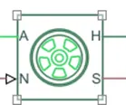
it contains H-mechanical hub of the vehicle which is connected to the H Of vehicle body A-axle of vehicle body which is an control by the shoe brake which has an input from the signal builder N=-it is nothing but the vehical speed or force which is positive if force is downward to vehicle S-it is the slip of tyre as an output given to the ps- eliminator which is eliminate an the physical signals.
- Vehicle body: it is nothing but the main component as the H-hub, V-velocity W-wind force, NR- Rear wheel , NF-Front Wheel, Beta-headwind speed and road inclination angle, respectively. As well veloity- 1/S- distance.
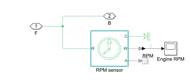
4].Engine Sensor:- it is just and the ideal rotational motion sensorAs it gives only the speed of the engine as an the output and it given to the input and cvt as an the input.
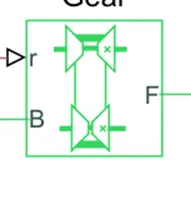
5].simple gear:- fixed-ratio gear or gear box. No inertia or compliance is modeled in this block. You can optionally include gear meshing and viscous bearing losses.
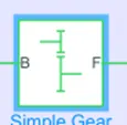
its just as an the simple gear ratio as NF/NB bearing as fractional losses as well as the mesh losses which takes an input from cvt and then it given to the real vehicle body as the input.
Dashboard:-
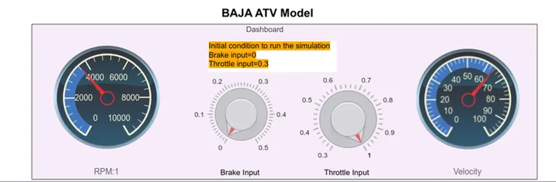
Dashboard:- it is used for indications of speed, rpm, breek input, throttle input.
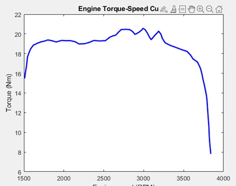
In this model used speed torque curve:
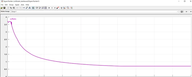
Signal builder: It is used for to set ratio
MODEL WITH THROTLE-0.3, BRAKE-0
Plote of Model:at throttle=0.3, brake=0
CVT Shaft Speed :-Primary RPM vs Sec RPM
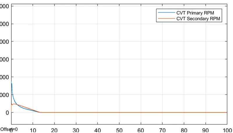
So by the shaft -speed curve at the staring when we accelerate an the vehical engine part as input or variable gear input (without gear) primary rpm starts nearly on 1800 rpm and at an same time, Due to the variable gear ratio it starts on the near 700 rpm,but due to less velocity or after some time the CVT goes to override as the sec rpm is more than primary rpm
Vehicle Max Speed:-
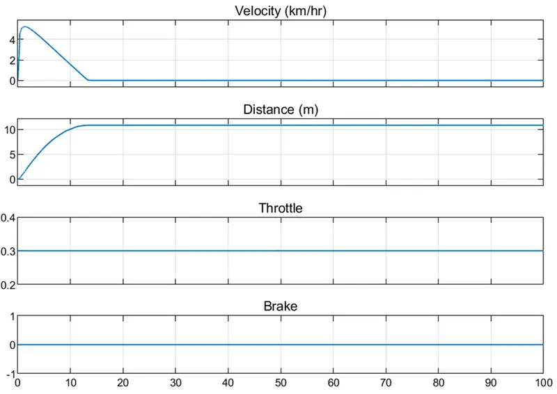
As when we apply an the input throttle as 0.3 with 0 resistance as break then the suddenly speed increases to 5 and drop down due these less speed vehicle goes upto only 10 m distance
Plote of Model:at throttle=0.5, brake=0
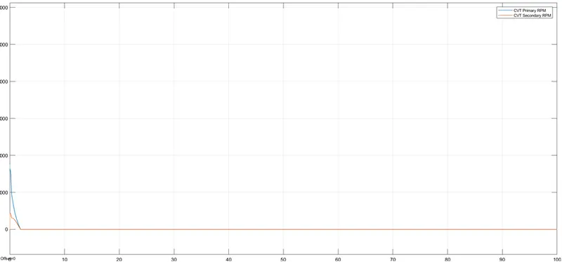
CVT Shaft Speed :-Primary RPM vs Sec RPM
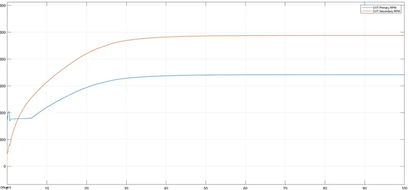
As same as above we give an input of 0.5 50% of throttle with no breaks are apply for an 100 seconds as above starting of primary RPM at 1600 rpm and secondary at an 700 rpm but then the sec RPM > prim RPM :- 4800 >3400
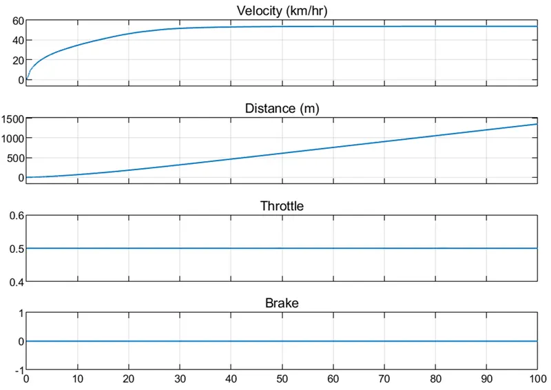
As same as the shaft speed when we apply an acceleration vehicle goes upto an the 1500m with 55 km/hr is speed.
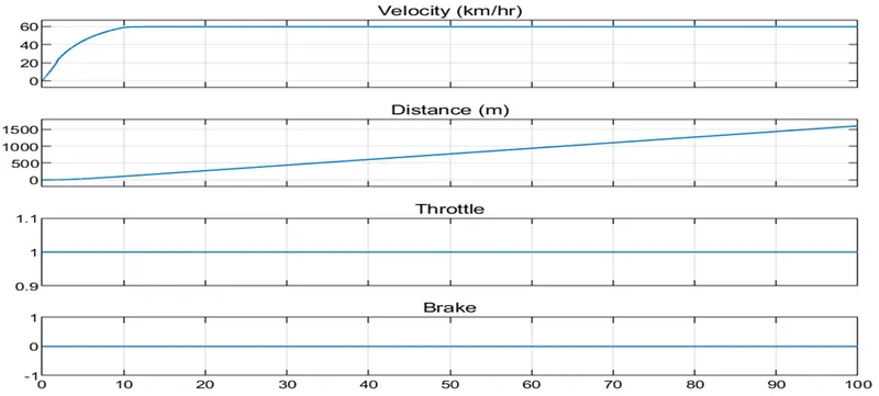
Plote of Model:at throttle=1, brake=0
CVT Shaft Speed :-Primary RPM vs Sec RPM As same as above we give an input of 01 100% of throttle with no breaks are apply for an 100 seconds as above starting of primary RPM at 1800 rpm and secondary at an 100 rpm but then the sec RPM > prim RPM as prim max is 3800 and sec is 5800rpm.
Same with an the maximum speed as 60km/hr
Plote of Model:-at throttle=0.3, brake=0.3
CVT Shaft Speed :-Primary RPM vs Sec RPM
As when we apply break and the accelerator, at same time then the primary shaft of engine start the rotating at high speed rpm but at same time breaks will be apply and then total rpm will be reduces to 0
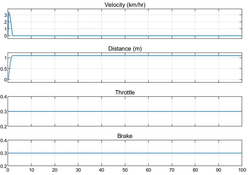
So as the vehicle speed goes to the top 3 and the distance only as the 1m.
Result:-
|
Throttle |
break |
Max(speed) |
Pri shaft (rpm) |
Sec shaft (rpm) |
|
0.3 |
0 |
5 |
1800 |
700 |
|
0.5 |
0 |
55 |
3200 |
4800 |
|
1 |
0 |
60 |
3800 |
5400 |
|
0.3 |
0.3 |
5 |
2000 |
500 |
Conclusion:- so as per the model the input to the CVT is by the signal builder so the rpm is not match perfectly or it takes an some time to match so we have consider as the input to cvt as the output of vehical body is an feedback signal.
MODEL (closed loop model)
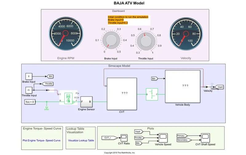
So as per the model as we give the input to cvt block as the velocity of the vehicle body output as the close loop system. So as we run the model with an change in the throttle and brake so as wrt change in the input output also to be change as well as the cvt also to be change.
Condition 1:-throttle =0.3,break=0;
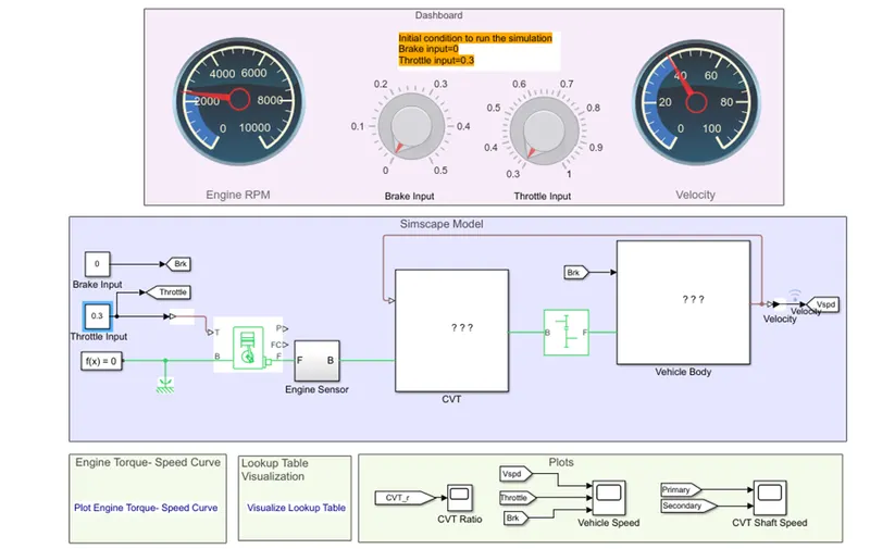
As we run the model we get an the
1.cvt ratio as:-
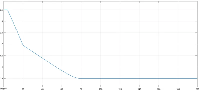
so as we get exactly good cvt ratio as compare to open loop system.
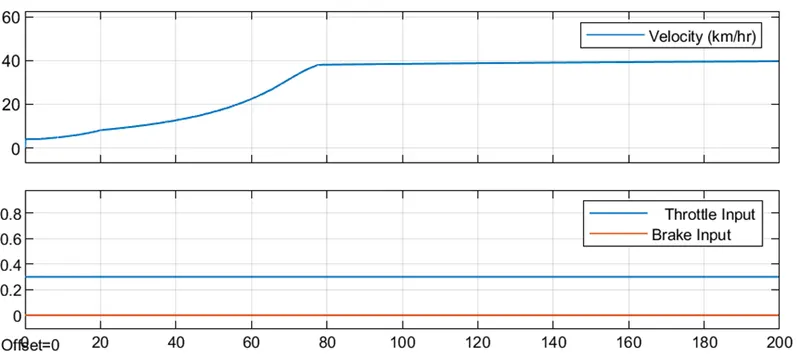
As well as when we give an input as the velocity so at that time speed for an the output, as for output it requires some time to increased.
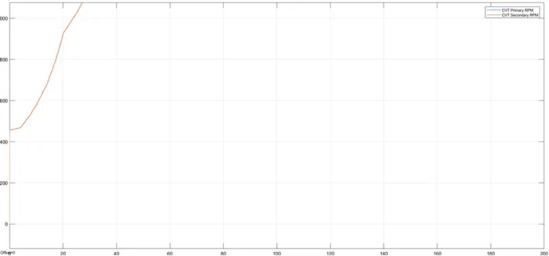
and due to the close loop system we get an sec rpm increses gradually
Condition 02:- throttle-1 ,break -0
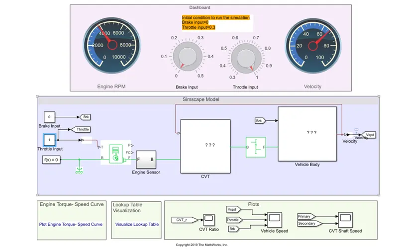
As we gets an the output as below
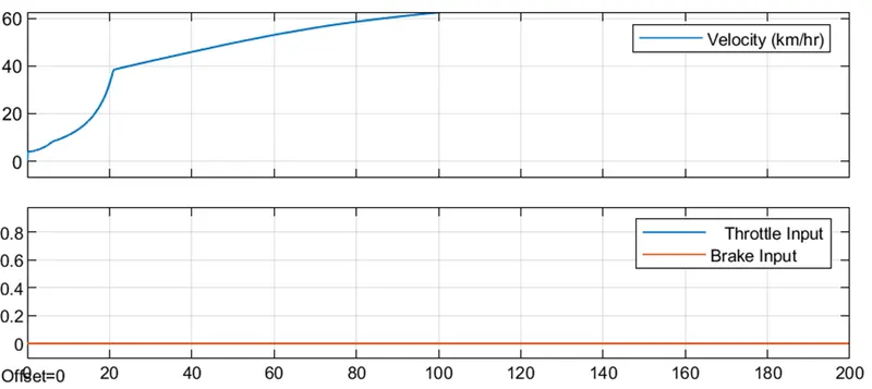
so as after giving an the suddenly input throttle speed increses rapidly and then it increases gradually,
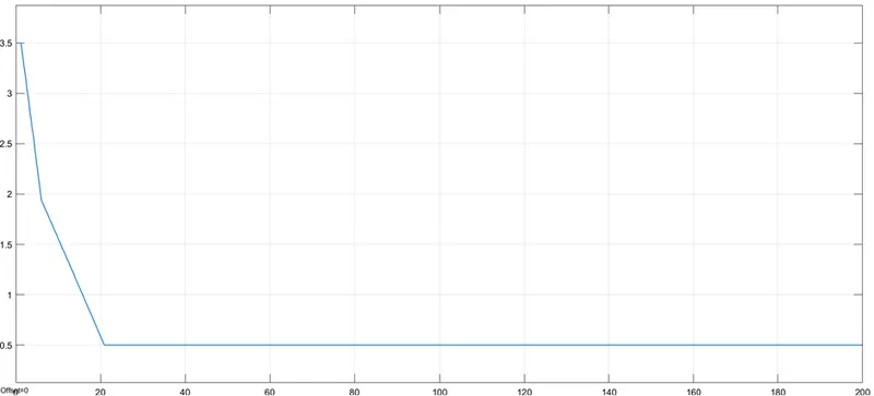
So as we get an the cvt as above
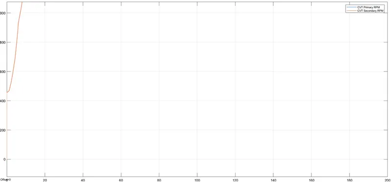
Condition 03:- throttle-0.3 ,break -0.3
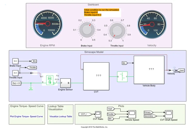
So as we give an the throttle as input as well as an the breaks are also apply so we gets an the output as belows.
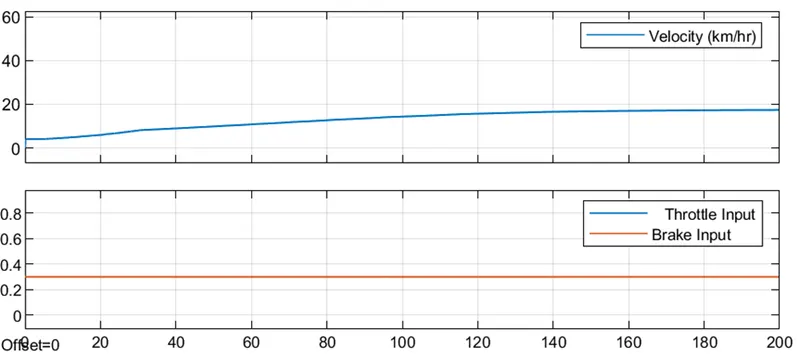
as when the start speed/ velocity gradually increses and then breaks are apply as velocity increases slowly.
Result:- as by compairing the both open and the close loop system and we get the diffrences From the result .