Project 1 Mechanical design of battery pack
Aim:- Design an the mechanical battery pack
Objective:- to design an the battery pack of 18kwh ,cell ANR26650M1-B
Introduction:-
Safety and reliability are the two key challenges for large-scale electrification of road transport sector. Current Li-ion battery packs are prone to failure due to reasons such as continuous transmission of mechanical vibrations, exposure to high impact forces and, thermal runaway. Robust mechanical design and battery packaging can provide greater degree of protection against all of these. This chapter discusses design elements like thermal barrier and gas exhaust mechanism that can be integrated into battery packaging to mitigate the high safety risks associated with failure of an electric vehicle (EV) battery pack. Several patented mechanical design solutions, developed with an aim to increase crashworthiness and vibration isolation in EV battery pack, are discussed. Lastly, mechanical design of the battery pack of the first fully electric bus designed and developed in Australia is presented. This case study showcases the benefits of adopting modularity in the design of EVs. In addition, it highlights the importance of packaging space for EVs, particularly in low-floor electric buses, as weight distribution becomes a challenge in these applications.
lithium ion batteries are the used various diffrent make of electrodes are cathode and due to this its chemistry changes as the output voltage also changes the ah capacity of an the battery
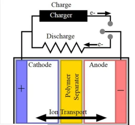
basic structre of an the cell:- as the battery made up of an the anode,cathod,saperator electrolyte and the 2 current carrying conductor al and cu
mechanical design of battery pack:-
- mechanicl vibration
- thermal managemebnt as the cooling
- controllig high impact face
- sercicability and trecycleability:-output is more life
Nanophosphate® High Power Lithium Ion Cell ANR26650M1-B
A123’s high-performance Nanophosphate® lithium iron phosphate (LiFePO4) battery technology delivers high power and energy density combined with excellent safety performance and extensive life cycling in a lighter weight, more compact package. Our cells have low capacity loss and impedance growth over time as well as high usable energy over a wide state of charge (SOC) range, allowing our systems to meet end-of-life power and energyrequirements with minimal pack oversizing
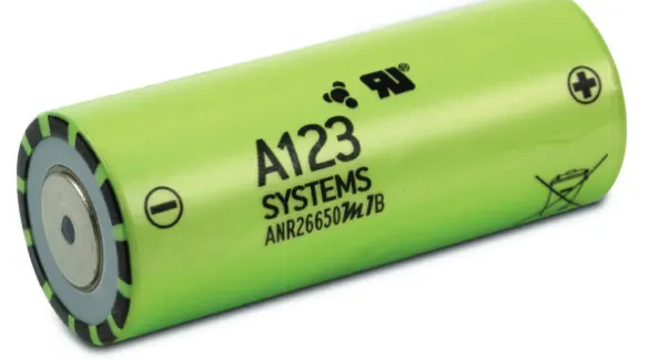
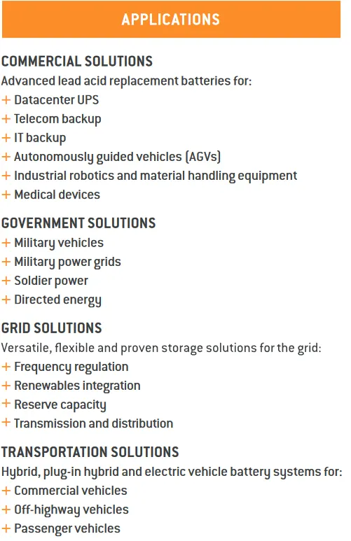
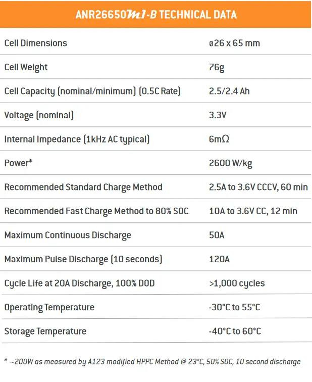
- so this is the application and the technical data of cell and according to the its characterstics we need to make an the mechanical battery configuration as the plot as belows.
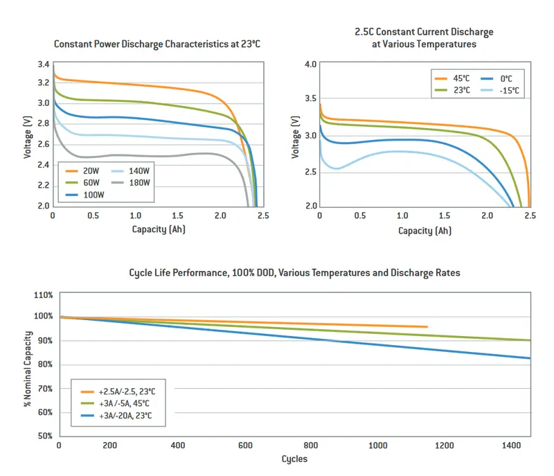
- so as from this it is an the same as the constant power discharge at an the characterstics and other will be an the constant current discharge at various temperature , as well as their is an the discharge rate as an the nominal capacity as the more current so discharge rate is also more
Design of mechanical battery pack calculations:-
- thus we need to an the capacity of an the battery pack of the 18kwh as the it has an the voltge of 3.3v and the ampere hour capacity of the 2.4 ah capacity so we need to an makes an series parallel connection of the cells as cell connected inseries will be have more voltage and other hand if the cells in parallel will be have an the ah capacity will be an more
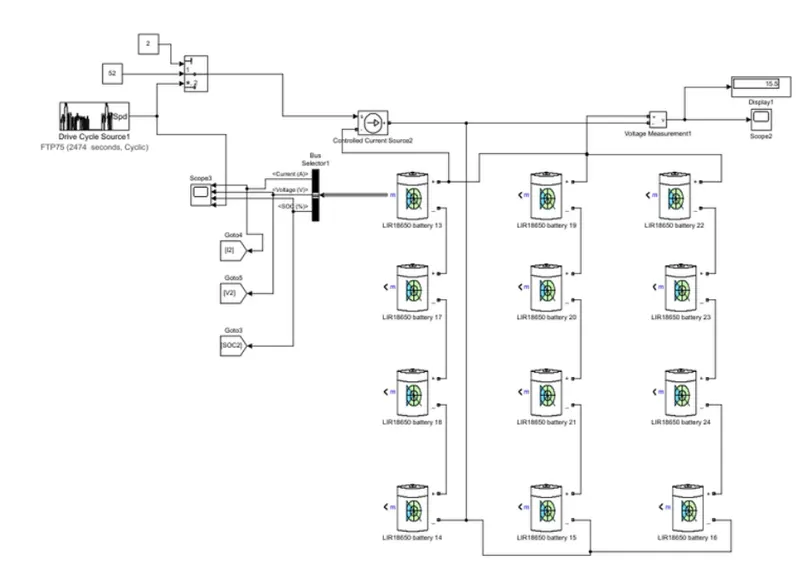
- so we can make an the series parallel connection of the battery to get an the kwh capacity with an the volthge and ampere hour capacity as the KWH=V X AH as need to fulfilled an the demand as by connecting an the number of cells connected in series form an string
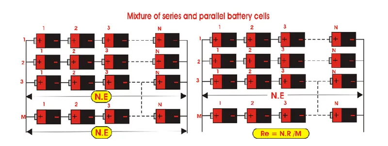
- consider as if the 1cell is 2 v connected as 6 cells in series so the voltge will be an at the 12v and the ah remains an the same as 2.5ah but if we connects an the cells 6 cells are the parallel so 2.5 x6 = 15ah capacity of an the cell. so we have to make an some calculations made as per the manufacturers data
- steps:-
- Calulations for battery pack :-as the volume,energy ,density,no of cells ,series and string,capacity,mass of battery pack,current ,peak current ,power ,peak power,
- battery dimension:- housing of casing as an the height ,breadth , and length of casing
- Cooling type:- which coolibg prefered as an the active or passive type of cooling
- installation:-loc of bms,accesible,parallel conn, optimum connection, cad design , mock up test
- assembly of battery pack:- balancing, cell containtment , cell isolation , bms placement ,power connection (no of cells , strip ,pvc heat sink film ,welder ,cel holder )
step 1:- calculations as per assumptions:- so as all we know that the vehical drive on the 330 volts to be consider as the 3 phase motor should be uses and from this we know the all number of cell connected in series and parallel
cell Dimensions - 26 x 65 mm 0.026m r=0.013
Cell Weight - 76g
Cell Capacity (nominal/minimum) (0.5C Rate) - 2.5/2.4 Ah
Voltage (nominal) - 3.3V
Internal Impedance (1kHz AC typical) - 6mΩ
Power* - 2600 W/kg
Recommended Standard Charge Method - 2.5A to 3.6V CCCV, 60 min
Recommended Fast Charge Method to 80% SOC - 10A to 3.6V CC, 12 min
Maximum Continuous Discharge - 50A
Maximum Pulse Discharge (10 seconds) - 120A
Cycle Life at 20A Discharge, 100% DOD - >1,000 cycles
Operating Temperature - -30°C to 55°C
Storage Temperature - -40°C to 60°C
1.sigle cell area:- as the area is imp factor by = 2 pi r^2 h ; so ;2 x 3.14 x (0.013)^2 x 0.065 = 0.0345m^3 volume.
2.energy of cell :- energy = voltage x ah capacity ; 3.3 x 2.6 = 8.58wh
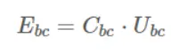
3.battery cell energy density;-
3.1 volumatric energy:- energy of cell / vol of each cell :- 8.58 / 0.0345 =248.62wh/m^3
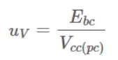
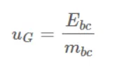
3.2 gravimatric energy:- energy of cell / mass of cell :- 8.58 / 0.076 = 112.89 wh/kg
4.total energy:- 18kwh =18000wh x 100
5.no of cells connected in series:- voltage / each cell voltage ;- 330.3 = 100 cells in series
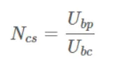
6.energy content of string :- 1 cell energy x series connected cell ;- 8.58 x 100 = 858wh of each string
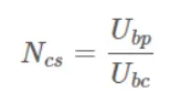
7.no of string in parallel:- energy capacity / wh series capacity ;- 18000/858 = 21.81 approx 22
so the battery pack of an the 100s22p is the 18kwh battery pack
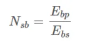
8 battery pack ah capacity = parallel string x each cell ah capacity ;- 22 x 2.5 ;-55ah
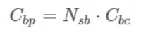
9.total number of cells = cells in series x cells in parallel;- 22 x 100 = 2200 cell required

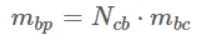
10.total mass of battery pack:- no of cells x each cell capacity = 2200 x o.76 = 167.2 kg
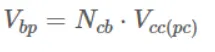
11.volume of battery pack ;- no of cell x each cell volume = 2200 x 0.035 = 77m^3
12.string peak current :- 1 cell ah capacity x series of 1 string ;- 2.5 x 24 ;- 60A

13 battery pack peak current :- ah capacity x 1 striing current ;- 60 x 22 ;- 1320amp
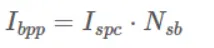
14.battery pack peak power:- string peak current x parallel strings ;- 1320 x 22 ;-435600 ;- 435.600kwh peak power capacity
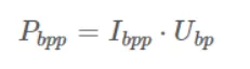
15 string contineous current:- its contineous charge current and the ah capacity ;- 10 x 2.5 ;- 25ah capacity
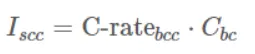
16 battery pack contineous current:- product of string current and the no of string battery pack
25 x 22 = 550A
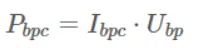
17. battery pack contineous power:- product of current and the voltage ;- 550 x 330 ;- 181500w ;- 181.5kwh
| manufacturer | A123 |
| no of cell in series string | 100 |
| string energy | 825wh |
| no of string | 22 |
| battery pack energy | 55ah |
| total no of cells | 2200 |
| battery pack mass | 167.2kg |
| bat pack vol | 0.077m^3 |
| battery pack peak current | 1320A |
| battery pack peak power | 435.6KW |
| battery pack contineous power | 181.5 KW |
| battery pack contineous current | 550A |
Battery Dimension:-
- as their is required an the housing which has an the total volume or area should be required as lego type housing may be required so hows an the housing may be define as some calculations
LENGTH:- as the length of housing may be as required as the 100 cells may be an connected between it as well as to maintained as the temp as the active type of cooling required so as in that case the spacer has to be placed so some area should be required in that case
Length:- (cell diameter + margin at both side ) x no of cells in series + clearance at two sides
:-(26 +4)100 + 60
:- 3060mm
Breadth:-as well as the no of cell in parallel or the parallel string so in that case housing has an the consider the width also.
:-(cell diameter + margin at both side ) x no of cells in series + clearance at two sides
:-(26 + 4 )22 + 60
:-720mm
Height:-height of cell housing is an the nothing but the cell individual height and the space for an the wiring :- cell height + space for an the wiring
:- 65 + 35 =100mm
so the final housing dimension will be an the 3060 x 720 x 100 mm is the total volume required in that case
Assembly of Battery pack:-
- so as from an the above we desigh the battery pack or system such that required an the following components as well as an the following instruments.
- connector
- spot welder
- nicket strip
- 2200 cells
- pvc heat sink film
- cell holder
- solder
by using all of these material we can make a simple pack of an the battery
Series string:-by an connecting the no of cells in the series we can make an the more voltage across it.
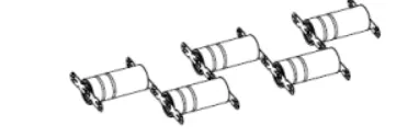
Parallel string:- as well as an the no of cells connected in the parallel we can increse an the ampere hour capacity of that cell
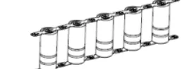
Lego connector :-as we are using an the lego connector because of if any 1 fells then it easy to accessible at that time easy to deconstruct the same way electrical and mechanical construction.
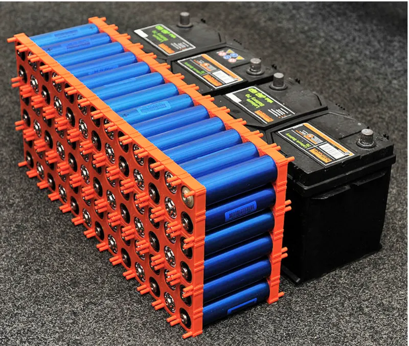
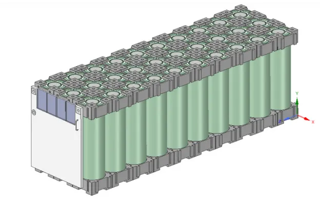
as from an the above we can connects the cells in modules and then as an the pack asssemblyby simple housing with an the lego connector
Nickel strip:- as in this battery pack as the no of cells are connected in series and parallel so the soldering is not the way to connect all the cells so we can connect all are the cells by an the spot welding by using an the nickel strips nickel has an the low relative resistance as an compare to other as steel is so cheap than the nickel so more wendors are used an the nickel coated material are used for an the spot welding,but due to the low resistance property of nickel as the steel material heated much more and their will be an the much more energy loss takes place at that place.
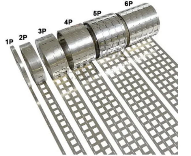
so as shown in the above figure as the strips can be form by the nickel strips it has an the certain configuration as the 2p,4p,6p and much more can be used.
- first as the no of cell in parallel and series configuration as an the how many connected in series and parallel .
- after this is then we can used an the mechanical structre to be required as the thermodynamics as well as the cooling of an the cells
- then the cell protection and the electrical connection as the overcharging ,overdischarging ,voltage and current protection etc.
General steps to design an the battery pack:-
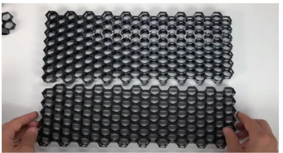
- as an due to the high density of cells so the we can choose hexagonal connectors and join them as belows their colour should be an black
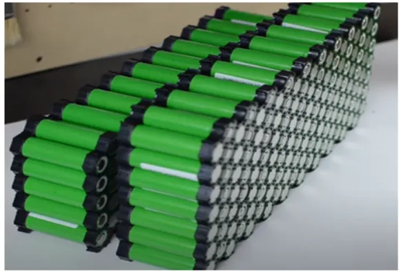
- after this place the cells alternatevely in the case and connect all the cells as the below shown kept positive and nagetive poles alternatevly adjacent rows
- after this make an the connection electrical as an the series parallel by an the spot welding in it makes an the cells series and then parallel connection.
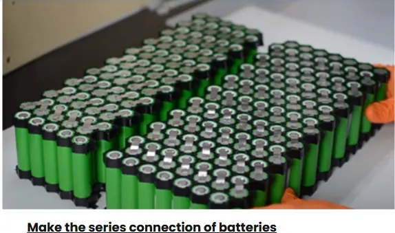
- and then make the connection as the parallel connection strips as the parallel to incteses and the ah capacity of an the battery
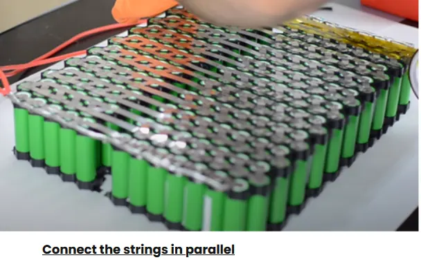
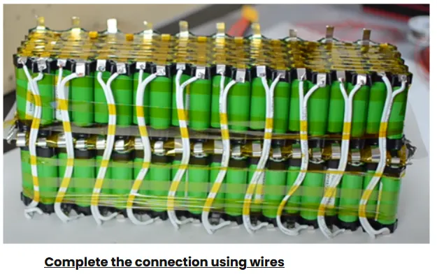
- then complete all the connection and then the attached the pcbs and ecu fuse switches are the protection devices in that ckt as the wiring as so the protection ckt also to be made in that case
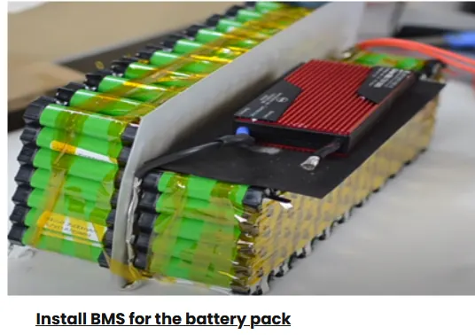
- install an the bms battery pack in that cell after all the connection for the protection of an the battery as the overcharge overdischarge overcurrent undervoltage as some are the protection ckt.
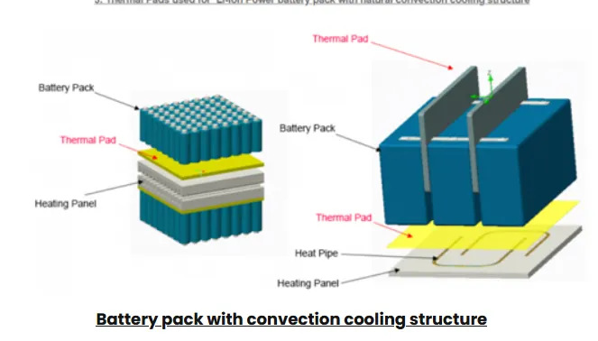
- then install the thermal protection to the circuit for the temperature control in this ckt,as the front and the back board thermal pad with on the metal sheet natural cooling of
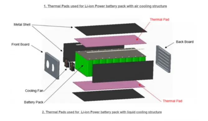
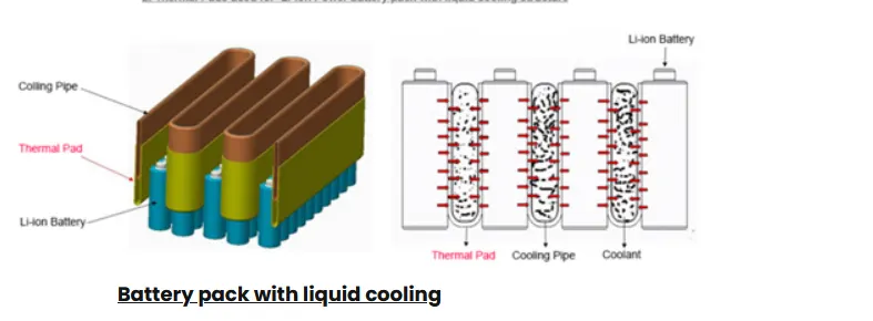
- other method will be an the liquid cooling in that case the passive cooling the jackets of glycol +water can be used in thay case as an the refrigant
- other is an the convetional cooling system in which the heating pipe type of the structre can be used it can be used where the battery heating should be required
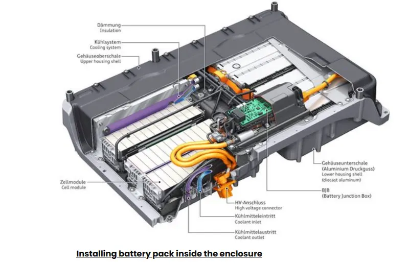
- installing all the battery pack in enclosure as the no of modules with an the thermal as well as an the bms and other cooling should be present in that case
- as their are the certain enclosures are available but out of this only an the it has an some important properties as an the
- lightweight
- shockproof and vibration proof
- fire protection as well as an the
- prevent electromagnetic radiation as well as an the
- low cost
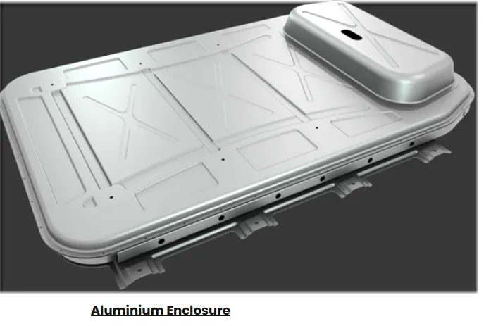
a]alluminium enclosure:-it has an the corrosive resistance in that case also the thermal conductivity in that also cool and heat the cells by this enclosure we can reduces the weight by 50% of total vehical
b] glass fibre based enclosure:-it provide high stiffness to the battery so as well as an the fireproof in caseofthe ewater and gases tightness,improve structral stiffness of the underbody as an the battery box covers as well as an the fueling caps are made up of an the glaass fibre
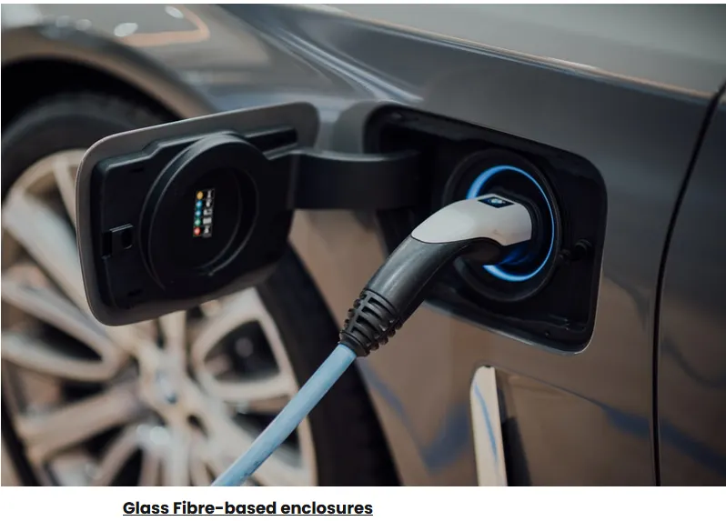
c] it is an the safest project working on the safest enclosere to the battery as an the production of the battery pack boxes in that cases it is an for the new buses in the usa arrivals supporting an the more advantages in that case
properties:-
-lightweight and robust enclosure
-carbon feature composite
-more layers for an the electrical conductivity and the electromagnetic radiation.
-partnership contribute to the all stages of project devlopement
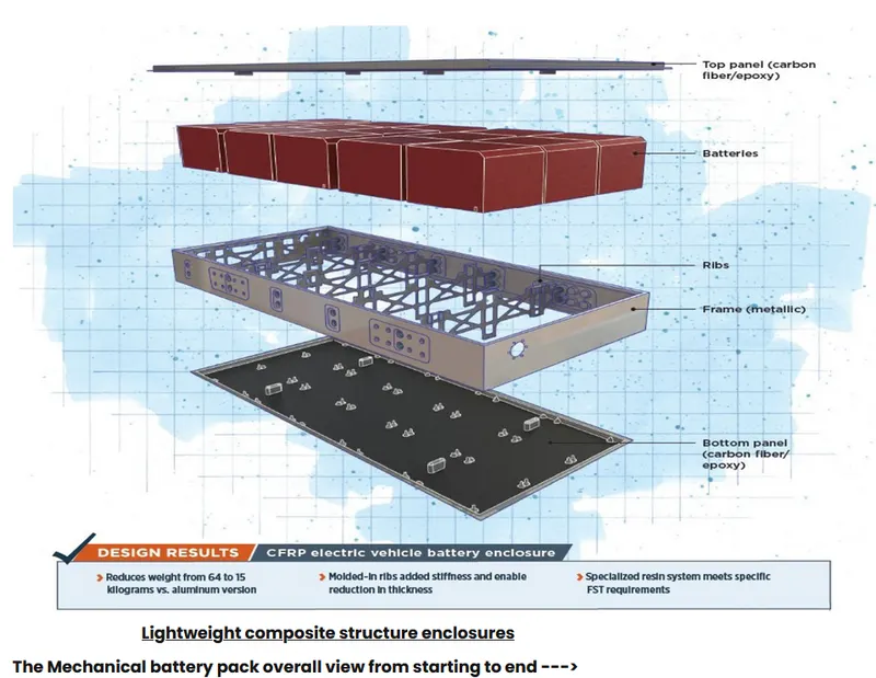
so it is an the enclosures battery with an the carbon enclosures are been used in that case to protect the battery
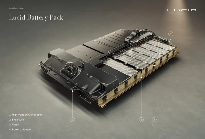
- their are the some installation guidlines
1.location of bms outside cell not an module
2.cell are testing and servicing requred so they are easy to accesible
3.direct parallel installation to avoid effect of the cell mismatch
4.optimum electrical connection min connection be obtain.
5.cad tools are the the used placements firstly design the cells and then the installation starts
6 before installation takes an the empty box and do test on it as mock up test are the vibration test,heating test ,noise test
- After installation their willl be an the assembly
1.balancing before an the assembly so charge in parallel and assemble in series.
2.cell containment:- as the cell defirmation will be happened so the place some distance between each celll by an the spacers
3.Cell isolation:- so as an the in case the whole body will be acts as an the -ve and we need to takes an the care
4.BMS Placement place an the bms system in that case
power circuit connection connect all the connection as optimum connection as possible
Conclusion:- so we study how to design an the battery pack mechanically.