Final Project: Design of an Electric Vehicle
AIM:- To design an the electrical vehical by using an the battary,controller, motor and vehical body by configure an the powertrain blockset.5
Objective:-
1]to make an the simple model as we have check all the parameters and low run time.
2]annalyse an the result. which are configure the diffrent parameters as the SOC ,current etc
Theory:-
so as aall we know that the vehical runs on the sourse like as an the convetional as the petrol ,diesel as well as the latest technology is the cng but due to the corona virus or the demand and supply diffrences the cost of the fuel like as an the convetional fuel as petrol ,diesel are increases. as well as the increses the emission also increases so the global warming also increase and to stop all it we have the new technology as the electrical vehical
"electrical vehical"
so as all we know that the eltrical vehicle it is just simple as the vehical run on the electrical motor which is propelled by an the battary it is an the basic working as an the conversion of an the energy as the electrical energy converted into an the mechanical or kinetic energy thus an the electric car function as an the plugging into an the charge points and tooks the electricity from the grids.thus an the store energy in the rechargabal battaries power an the electrical motors ,turn into the wheels or an the vehical body
as from the above we know that the how electrical vehicle actual working and their main components or the parts as belows
Main parts of an the electrical vehical as belows to design:-
"Components "
1]motor
2]Battery
3]convertor
4]controller
5]vehical body/tire
6]drive cycle- to annalyse an the power and energy required to drive an the vehical
7]driver controller- it is for an the inputs to the vehical as get an the breaks or accelerations on it
"Block Diagram"
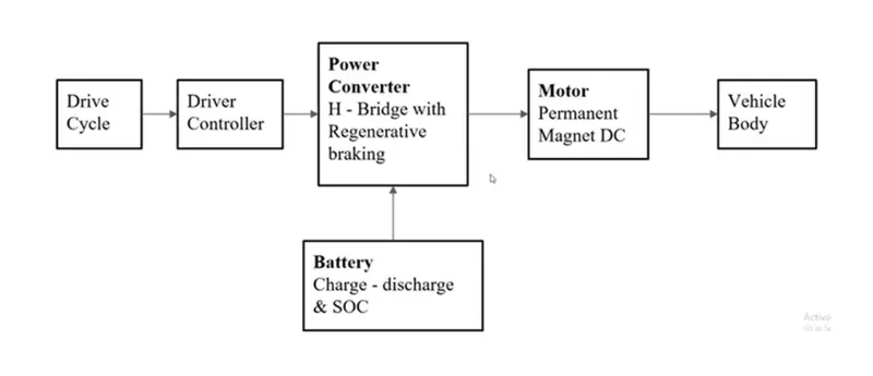
so all are the above are an the components with the some other components as the mechanical are the wheels , gear systems etc
"Procedure"
consider we haves an to makes an the electrical vehical model of the offroad like a nexon so how is to design
1]identify the how much propulsion power required by the vehical so the tire.body of vehicle ,gear system, payload and diffrent forces acts on it has to be consider.
2]so after finding the how much actually propulsion power is required and the ammount of torque specific motor should be choose as ac ,pmdc,bldc
3]after consider an the motor choose the battery pack as its weight size,choose as an the how much ah capacity to reach the specific ammount of distance.
why need to identify propulsion power:-final output of vehicle is an the propulsion power as the we need an the speed with the some amount of the finite torque. so the study starts from here ,so the simulation or the mathmatical model needs to an built before hardwear for flexibal design operation so after an the propulsion power will be design starts the vehicle body and all other parameters:-
Wheel and Vehical body
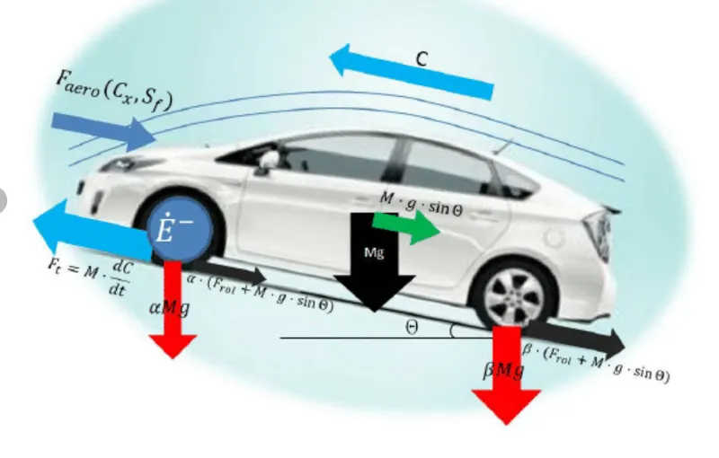
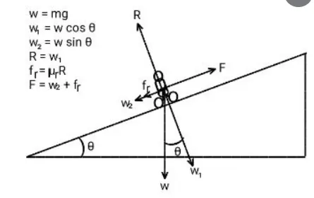
as all we know that the mainly 3 forces acting on the electrical vehicle as an the
1]tractive force:-it is an the total force acting on vehicle
1.1]rolling resistance force:-it is an the force due to the tire contact within the surface
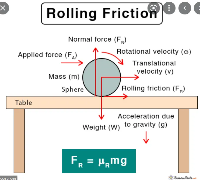
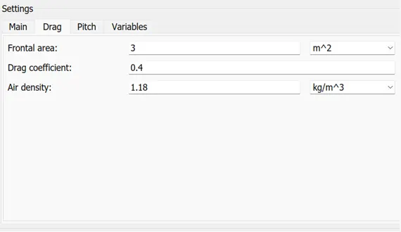
1.2]Aerodynamic drag:-it is because of an the air opposition to the vehicle because of the design of car
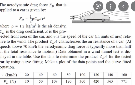
1.3]Hill climbing force:-the consider as the up gradient and down gradient as hill climbing situation etc
COMPONETS WITH Configuration:-
A]Tire :- so we can starts within the vehical body so it consist of an the wheels 4 wheels as we are devloping an the four wheeler, so it represent an the longitudional behavior of the highway or road it consist of an the (tire inertia ,stiffness,damping,rolling resistance ,shape size ,mass of an the tire.

Conserving ports
A-Mechanical translation to axle where the actual wheel is mounted
H-Mechanical translation to the hub it transmit the thrust devloped by the tire to vehicle body
Input port
N-it is an normal(NF-Normal front ,Normal Rear as body is connects to it
Output port
S-Physical input to as the slip of an the tire and surface of contact
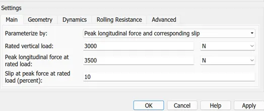
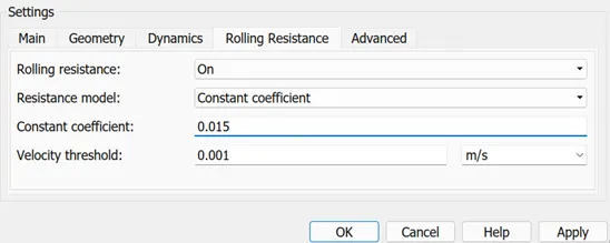
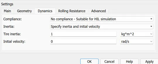
so as per an the vehicle tire design we consider as an the tire is the fortuner
- so we are consider as an the vertical load on each tire will be 3000N,
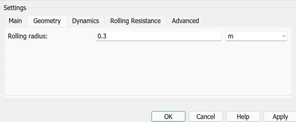
- geomtry as an the tire radious is 0.3m
- we are put an the rolling resistance of an the tire is as an the 0.015 within the threshold value of an the 0.001
- as wellas consider an the tire inertia as an the 1kgm^2
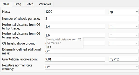
B]Vehical Body:- it is an the vehicle body where an the the wheels as well as the accelerator and the other parameters are to be an connected it has an the
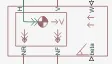
input parameter:-
w(wind):-it is an the input to vehicle body as the wind is opposes to it
beta:-grade angle in radians
H- hub it is an the conservating block as shows
outport
NR:-normal force on the rear axle
NF:-normal force on front axle
v:-velocity it is an the outport result
so as connect all the wheels to the vehical body make an the whole vehicle body as shown in the diagrame.
C]Diffrential:-it is an the simple gear between the driveshaft and the carrier,as pinion gear attach to driveshaft and the bavel gear is attached to the carrier as well as including the inertia, mesh and viscous losses .
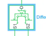
outports:-
S1, and S2 are mechanical rotational conserving ports associated with the driveshaft and the two output shafts as the "D" rotates in the clockwise so the s1 and s2 also rotates in the clockwise direction as well as the sungear are attached to it at the drive
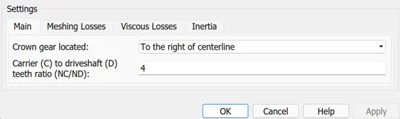
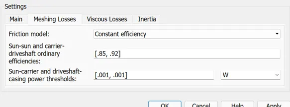
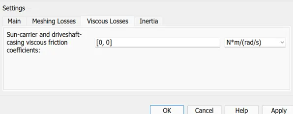
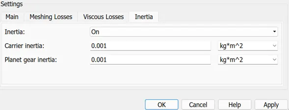
- so the main as the crown gear is attached in centre within the gear ratio of an NC/ND is 4 as if carrier move 1 teeth as 4 teeth of driveshaft has to be an required.
- mesh losses as the friction losses takes an consider as an the 85 to 90
- zero viscous loss and the inertia of gear is carrier(0.001),planetory(0.001)
D]Simple gear:-
B-Base
F-follower
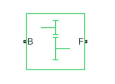
conservating ports
B- Base it is an the input port of an the motor shaft
F- it is an the output port where is an the diffrential /axle can be connected
simple gear:-it is an the simple gear where an the simple gear input is given as an the from the motor as simply ration it to form an the gear mechanism within consider as an the viscous and the meshing losses as well as their is an the one parameter as the output shaft in same direction of the input shaft.
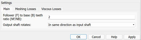
- as we have consider as an the viscous and the friction loss as 0, only the gear ratio B/F is 2
E]Motor:-
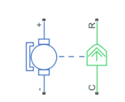
so we are using an the simple DC Motor as an the mechanical output is connected toward an the gear and an the diffrentials ,as well as the inputs are connected to the h-bridge convertor by the battary terminals also add to it. we can select an the motor parameters as an the electrical parameters and mechanical parameters as well as an the fault also in the motor
so we are consider as an the simple dc motor are been used
R-casing of the mlotor connected with an the mechanical model
c-casing of an the motor connected with an the common mechanical translation referance
+ve its an the positive signal from an the H-bridge as the motor +ve terminal
-ve its an the motor nagetive te rminal
so we can set an the parameters as an the mechanical and electrical in mechanical power as an the electrical torque-: speedin rpm.KW rating ,no load speed ,full load speed etc.
parameter configuration as belows:-
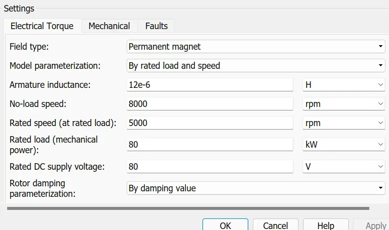
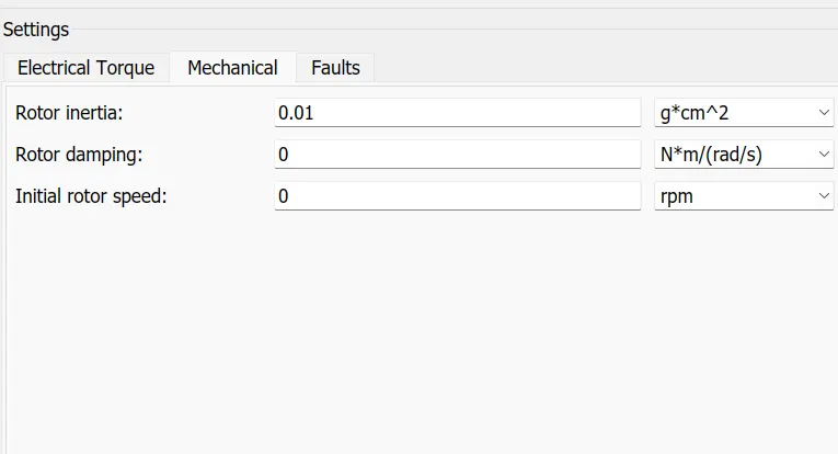
- as we are used the permanant field dc motors,with an the 80v dc ,80kw,with an the rated rpm as 5000
- as consider as an the mechanical rotor inertia is the consider as an 0.01 and faults consider as an the no any open winding fault.
so the diffrent types of motors are used in electrical vehicle as the below as:-
1.PMSM(permanant magnet synchronous motor)
2.BLDCM(brushles dc motor)
3.IPMM(interior permanant magnet motor)
4.PMSRM(Permanant magnet switch reluctance motor)- it is used in tesla as well as in nissan leaf
5.ACIM(alternating current in duction motor)
6.IPMSynRM(interior permanant magnet synchronous reluctance motor)
H-bridge:-
this block reperents an the H-bridge motor drive it can be power sourced by an the PWM ,as the motor is powered if the pwm voltage is above to the enable threshold voltage ,if an the rev port voltage is greater than the reverse threshold voltage then the output voltage priority is reversed,as if break port voltage is greater than the breaking threshold voltagethen output are short circuited via one bridge arm in series with an the parallel combination of second bridge arm and freewheeling diode as an the voltage ports as the brk,pwm,rev has to be define with relative to the referance port.
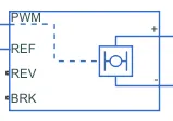
the following are an the parameters are has been selected fir the H-bridge
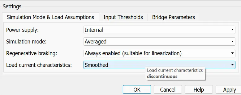
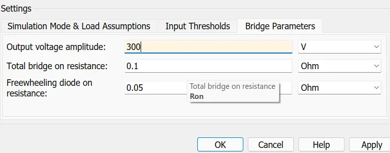
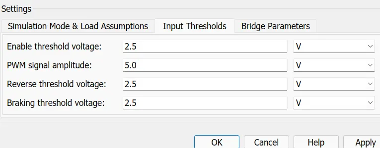
so considering all the parameters are been selected for an thr H-Bridge
Controlled PWM Voltage:- it creat an the inputs to the pwm volatge across an the pwm and ref as an the Hbridge input it should be selected as an the average not an the pwm.
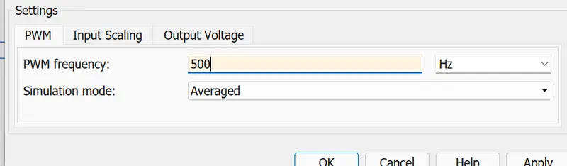
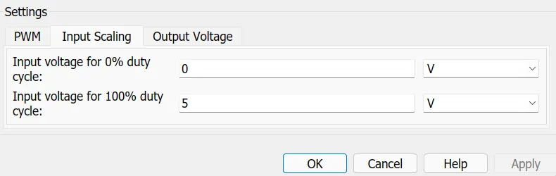
This block creates a Pulse-Width Modulated (PWM) voltage across the PWM and REF ports. The output voltage is zero when the pulse is low, and is equal to the Output voltage amplitude parameter when high. Duty cycle is set by the input value.
Battery:-
- we are used an the generic battery in these case because we has to run these model for an the long time finite run
- according to the block model rezistance is in the series resistance and the voltage charge source battery can be charge
- to ensure the battary supply current as per the requirement we are used current sensor and the controled cureent sourcs

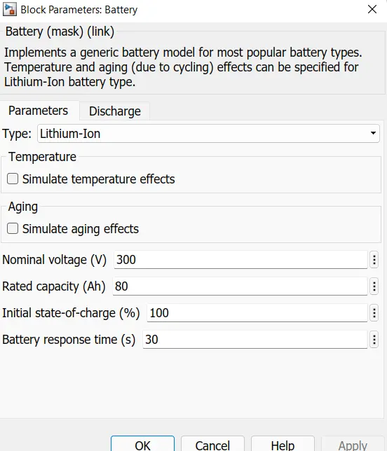
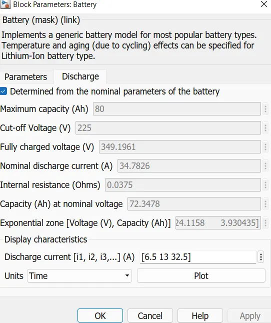
so these are the parameters to be set
so to know the state of charge of an the battery we have an to add the soc subsystem or block in the system,-
Battery state of charge:-
- small subsystem is for an the measuring battery state of an the charge, takes the battery current as an the input of the system
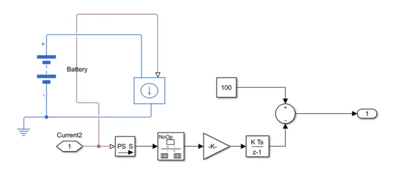
- soc calculate by an the substract it from the rated capacity of an the battery and current integrated wrt time to get the charge in coloumb and converts it into the ampere hour and these ampere hour substracted from an the charge capacity of an the battery
- so the remainning charge is converted into an the battary soc in percentage.
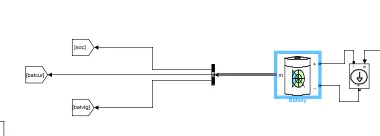
- we are used another battery as it have already soc and vtg and current
Longitudinal driver:-
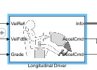
longitudinal driver it is an the working like an subsystem as an the driver which is an inputs have are the vehical feedback speed, vehicle referance speed , grade can be add and at the output it give an the acceleration and the breaking command.
parameters:-
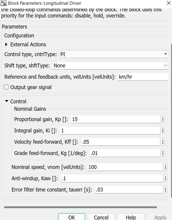
so the logitudinal driver it has an the input of the pi controller as by changing an the parameter we can change the logitudinal driver patameter
Input:-so the we can give input as by the multiport switch as to annalyse an the we haves an the inputs as ftp75 cycle, WOT and the changing input by slider gain.
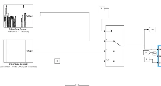
so we can gives an the input to the vehref by an the multiport switch.
Final Model:-
so the final model looks like as
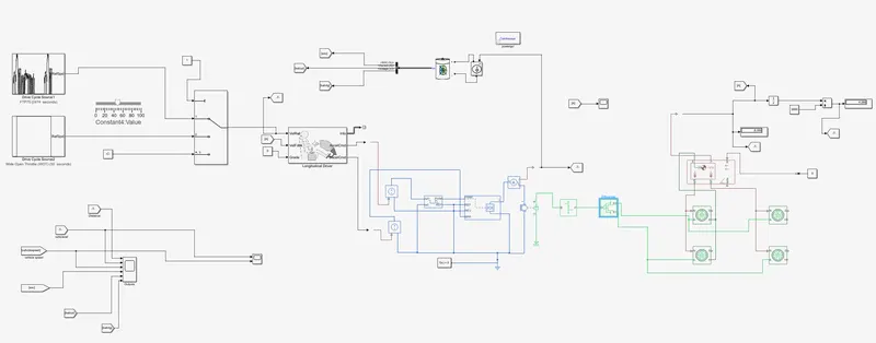
so the model looks like as an the above
Results:-
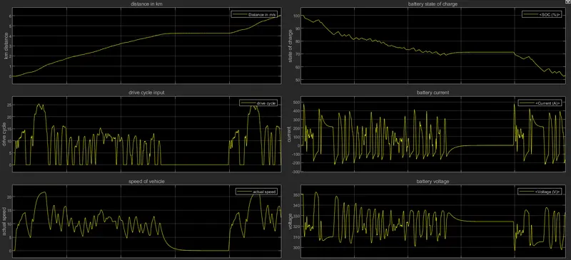
Output results or graph should be like as above:-
1]distance in KM:-So vehicle runs at upto the  6.031 m/s. distance
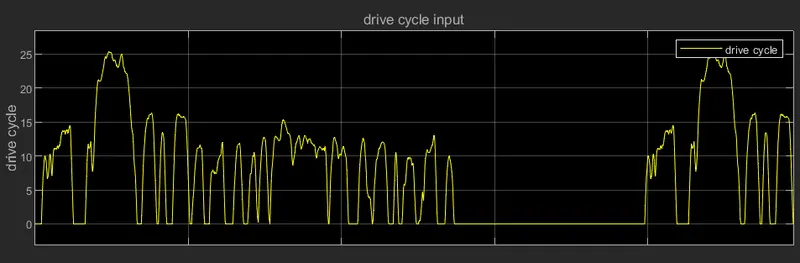
2]Drive cycle input:- federeal test procedure 75 can be used
3]speed of vehicle:- so by an driving the vehicle drive cycle it has an the drive max speed will be 23 m/s
4]state of charge:-so by apply an the drive cycle ftp75 vehicle runs on the 23 m/s with an the speed of it has an the soc is 53%
5]battery voltage:- vtg vary from 350 to the 298 voltage.
6]battery current:- battery current should be vary from an the 450 to -180 so vehicle be regenerative breaking mode so discharge current > charge current.
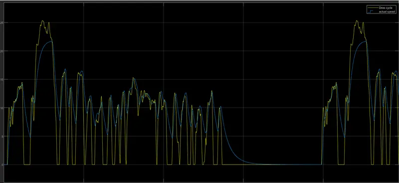
as we compare an the drive cycle with an the vehicle speed as an the vehicle try to match an the drive cycle.and an during the deacceleration the vehicle is on costing period.
Conclusion:-
1. so as we can charge full battery battery can discharges to 53%
2.vehicle runs on the 23m/s
3.vehicle can be generates energy as the regenerative breaking as battery can be charge.