Week-6 Challenge: EV Drivetrain
Q1.Which types of power converter circuits are employed in electric and hybrid electric vehicle?
Ans:-
Aim:-1.to know all the types of convertor and their function
objective:- to know how working of the actual power convertors
A converter is an electrical circuit which accepts a DC input and generates a DC output of a different voltage, usually achieved by high frequency switching action employing inductive and capacitive filter elements.
A power converter is an electrical circuit that changes the electric energy from one form into the desired form optimized for the specific load. A converter may do one or more functions and give an output that differs from the input. It is used to increase or decrease the magnitude of the input voltage, invert polarity, or produce several output voltages of either the same polarity with the input, different polarity, or mixed polarities such as in the computer power supply unit.
The DC to DC converters are used in a wide range of applications including computer power supplies, board level power conversion and regulation, dc motor control circuits and much more.
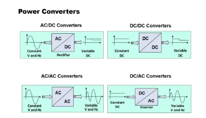
The converter acts as the link or the transforming stage between the power source and the power supply output. There are several kings of converters based on the source input voltage and the output voltage and these falls into four categories namely the AC to DC converter known as the rectifier, the AC to AC clycloconverter or frequency changer, the DC to DC voltage or current converter, and the DC to AC inverter.
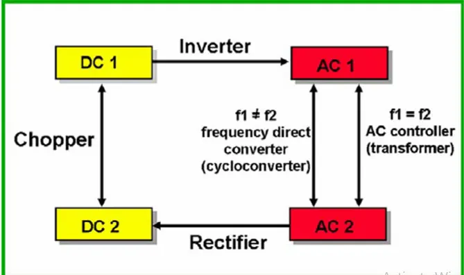
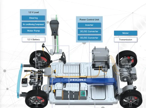
so as from above we know that the mainly 4 types of convertor as
A)Chopper (dc-dc convertor):-
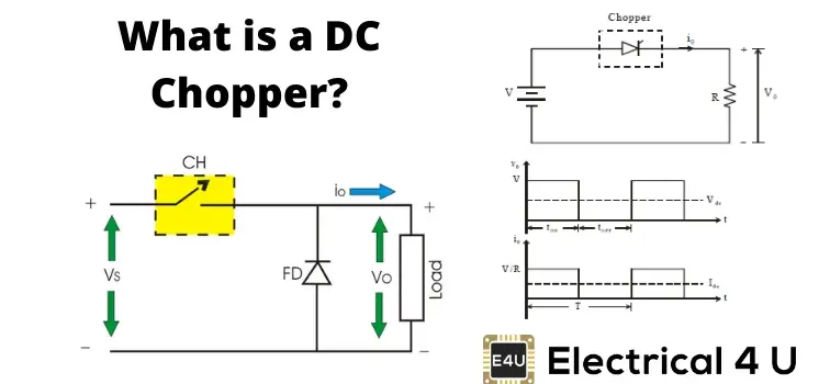
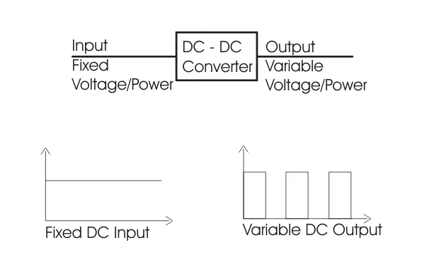
DC to DC converter is very much needed nowadays as many industrial applications are dependent upon DC voltage source. The performance of these applications will be improved if we use a variable DC supply. It will help to improve controllability of the equipments also. Examples of such applications are subway cars, trolley buses, battery operated vehicles etc. We can control and vary a constant DC voltage with the help of a chopper.
Chopper is a basically static power electronics device which converts fixed DC voltage/power to variable DC voltage or power. It is nothing but a high speed switch which connects and disconnects the load from source at a high rate to get variable or chopped voltage at the output.
(Invertor)DC-AC Convertor:-
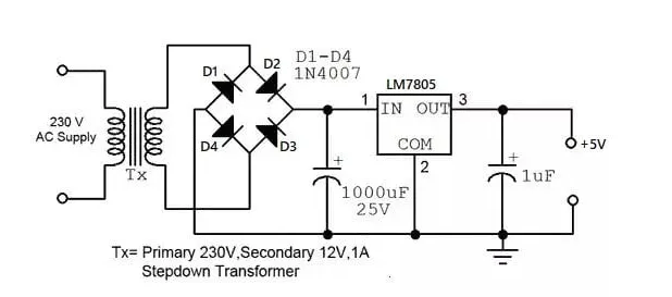
Firstly, the converter circuit used in the front part constantly converts alternating current to direct current. This process is called rectification. The wave’s direction and magnitude changes periodically over time since alternating current is a sine wave. Therefore a diode, which is a semiconductor device, is used so as to pass electricity in a forward direction to convert it into direct current, but not in the reverse direction.
When direct current goes through the diode, only the forward direction passes electricity and a positive peak appears. However, the other half of the cycle will be wasted because it does not pass the peak in the negative direction. The reason why the diode's structure is shaped like a bridge is so that it can pass the negative peak in a forward direction. This is called full-wave rectification due to the fact that it transforms both the forward and negative wave peaks.
However, full-wave rectification by itself cannot produce a smooth waveform as traces of the alternating current and rippled voltage fluctuations will remain. Therefore, in order to clean these up, the capacitor is repeatedly charged and discharged, gently smoothing and changing the waveform close to that of direct current.
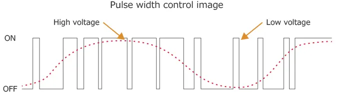
The inverter circuit then outputs alternating current with varying voltage and frequency. The DC/AC conversion mechanism switches power transistors such as "IGBT (Insulated Gate Bipolar Transistor)" and changes the ON/OFF intervals to create pulse waves with different widths. It then combines them into a pseudo sine wave. This is called “Pulse Width Modulation (PWM)”.
The computer controls the pulse width automatically. Some of the dedicated one-chip computers that control the motor include a product with the PWM function pre-installed. This makes it possible to create pseudo sine waves of various frequencies and control the rotation speed of the motor simply by specifying desired parameters.
Convertor(AC TO DC):-
AC to DC Converters are one of the most important elements in power electronics. This is because there are a lot of real-life applications that are based on these conversions. The electrical circuits that transform alternating current (AC) input into direct current (DC) output are known as AC-DC converters. They are used in power electronic applications where the power input a 50 Hz or 60 Hz sine-wave AC voltage that requires power conversion for a DC output.
The process of conversion of AC current to dc current is known as rectification. The rectifier converts the AC supply into the DC supply at the load end connection. Similarly, transformers are normally used to adjust the AC source to reduce the voltage level to have a better operation range for DC supply.
AC to AC convertor:-
The working principle of AC Voltage Controller is based on either of two methods: Phase Control or Integral Cycle Control.
In Phase Control method, the phase relationship between the start of load current and the input supply voltage is controlled by controlling the firing angle of the thyristor.
In Integral Cycle Control, the AC input supply is switched ON for some integral cycles and turned OFF for further number of integral cycles. Integral cycle control is mainly used for applications where the mechanical time constant or thermal time constant is quite high of the order of some seconds. For example, mechanical time constant for many of the speed control drives, or the thermal time constant of the heating loads is usually quite high. For such applications, almost no variation in speed or temperature will be noticed if the control is achieved by connection the load to the source for some on-cycles and then disconnecting the load for some off-cycles. This form of power control is the integral cycle control.
Figure below shows the circuit diagram of a single phase full wave AC voltage controller:
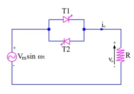
The circuit comprises of two thyristors connected in anti-parallel. Anti-parallel connection is done so that thyristor (T1) is forward biased for the positive half of the input supply voltage whereas thyristor (T2) is forward biased for the negative half cycle of the input AC supply. Method of phase control is used to achieve output voltage control.
When T1 is forward biased, it may be fired to turn it ON. The firing angle of thyristor may be chosen based on the required output voltage. If the output voltage requirement is more, the firing angle (α) should be less.
Q2.An Electric Vehicle's powertrain with 72V battery pack in shown in the diagram below. The duty ratio for acceleration operation is 'd1' and for the braking operation the duty ratio is 'd2'
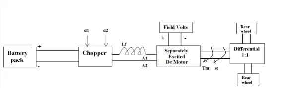
The other parameters of the electric vehicle is given below,
Motor and Controller Parameters:
Rated Armature voltage= 72 V
Rated armature current= 400 A
Ra= 0.5Ω, KΦ= 0.7 Volt second
Chopper Switching frequency= 400 Hz
The vehicle speed-torque characteristics are given by the below equation

What is EV steady state speed if duty cycle is 70%?
- SO AS COMPARING AN THE 2 EQUATIONS WE GET AN
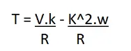
24.7+(0.0051)W^2=(V.K/R)-(K^2.W/R)
24.7+(0.0051W^2)=(72*0.7*0.7)/0.5 - (0.7^2*W)/0.5
W^2+192.15W+8992.15=0
SO TO FIND THE ROOTS AS
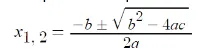
so as comparing an the equation with the above and we get as the output as the
Wm=38.92rad/sec
Q3.Develop a mathematical model of a DC Motor for the below equation using Simulink.
ωω= V/Kϕϕ -Ra/Kϕϕ^2.T
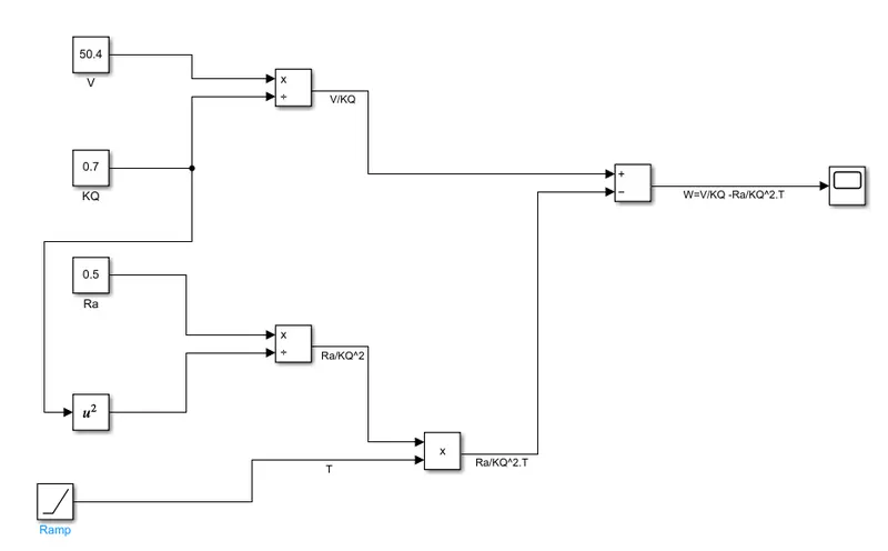
so it is the mathmaticle model and the plot is below as the
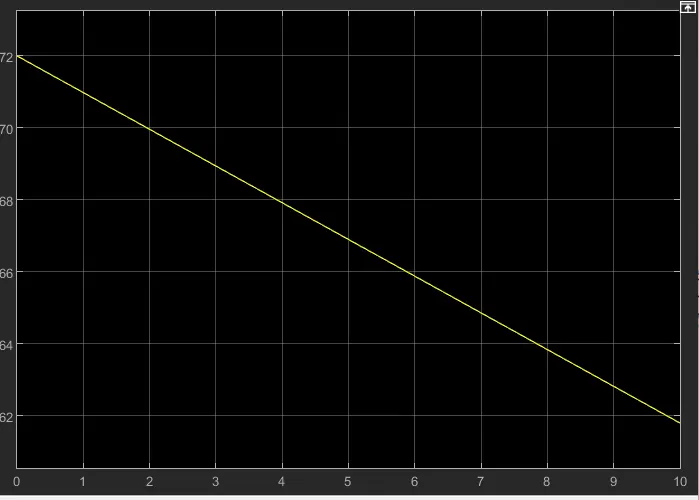
it is the plot of speed Wm
Q4
so the other is said the diffrenecs between the motors mainly as the dc motor and induction motor as an now days the lead acid battaries are replace by the lithium ion battaries. so actually other says the what actually diffrences in construction working what are the similarities also.staring with an the dc motors:-as the dc are the brushlesss dc motors with having 2 magnets in rotor that generate an the permanant magnetic field.in turns magnetic field enter the stator field of thick laminations so produce an the torque interaction between them as rotor rotates so as necessity of magnitude and the polarity of stator is also varied and right way that toqrue remains constant as conversion as the electricle to mechanical so without an the invertor its device are the uselessso other is an the induction motors by tesla 1889 as 3phase induction motor and the brushless dc motor are same as identicle only the diffrence is the distribuited winding as an the diffrences into the winding unlike an the BLDC rotor of an the induction motor has no magnets include in rotor.when the current flow into the stator winding produce an the rotating magnetic field as magnetic field of rotor is the diffrence between stator magnetic field and the rotor magnetiuc field the shorted structre is proportional to the speed diffrence between rotor and the electricle frequency
So author writes this blog to retain the differences between the two most commonly used motor drives in the automobile industry as one is the DC motor and other is the AC motor the DC brushless motor drive and the induction motor drive repair goes into detail about the difference in construction working and cost between the two drive types however with what he has written he has not arrived at the conclusion that one type is better than the other in the last lines of opening paragraph repel write that there is no one best engine type and that is it it all a matter of personal preference when it comes to choosing engine it is in the same regard that he and the blocks stating that there is no winner when it comes to motor drive selection either in sqlite of both motor drive is having similar it is they also have their benefits and disadvantages
Full DC brushless motor or Drive we have told that their construction implements two or more permanent magnets are used at the rotor to generate a DC magnetic field it also consists of stator which is made up of thin stag lamination to reduce the Eddy current losses it also use the inverter for the current control meaning that it cannot run on DC power supply as the current direction has to change repeatedly in the maintain constant torque respectively
As compared to the induction motor it can be used only deep Tech power from made directly and do not require any conversion part like as a inverter to start the drive
As if we consider and induction drive the induction drive cannot be directly e run on DC power supply and are solely dependent on AC power supply also when they are connected to three phase main supply the rotor rotates at a constant speed and also have a limited starting torque as compared to DC motor as well as Tik Tok in order to rectify this and inverter can be used to operate the induction drive from a DC supply or a battery also if their inverter frequency is varied then the constant speed is also no longer it is one of the major issue it can be varied
DC brushless drive use permanent magnet and cannot change the strength of the magnetic field if it would be a desire desire if they could because when the maximum torque is needed by the rotor the magnetic field strength should be also be a maximum level this allows the inverter and motor current to be at minimum thereby reducing the power loss by heat dissipation similarly when the torque required is minimum the magnetic field strength should also be minimum to reduce hysteresis and Eddy current losses the permanent magnets used is also quite expensive costing as a 50 per kg and their magnetic field are difficult to control if a para magnetic material gets close enough to the field
In other hand induction drive do not have permanent magnet and so they can vary with their magnetic field strength if we use with smart inverter they can be operated with minimum hysteresis and Eddy current losses and maximum efficiency as the magnetic field strength can be changed according to rotor these losses do not increase If the size of induction drive also increase but as a DC brushless drive gets bigger its losses increases and their efficiency reduces so induction drive has a cost advantage as compared to DC brushless drive all the DC brusted drive generate Lays hit at the routers more easily and have pig point efficiency than the induction drive in addition the DC brushless motor can operate at Unity power factor I even as compared to induction motor induction motor can operate on 85%
Conclusion:
Repel has collaborated the different aspects to compare the induction and DC brushless motor drives and has detail the advantages and disadvantages of what type as mentioned earlier at the end of the day it depends on the preference of the user If a user seeking a high performance with comparatively Lasik cost than the induction drive will be better suited for those requirement however it is Hai pick point efficiently high power factor and easy to control that uses Sikh then the DC brushless drive would be smarter choice both types have their own advantages and disadvantages as well has have their place in automobile industry and will retain their relevance in their respective application to repel believes that due to increasing performance of vehicle Vande both may be used side by side Under the Hood of electrical in order to get the best of both drives this would result in New kind of hybrid that combines characteristics of ordinary vehicle eg sedanand with that of a sports car.