Week - 4
answer:-
Q1.Implement control logic of a “washing machine” using Stateflow as per given sequence:
- If the power supply is available, the system gets activated
- If the Water supply is not available, stop the process & indicate through LED
- Soaking time should be 200s followed by Washing time of 100s.
- Then rinsing happens for next 20s & dryer runs for 50s
After all the processes have completed turn on the finished LED
Process:
1) I took chart block and creat a logic in it with the help of state which is shown above.
2) To chart input i gives the input from simulink and output to simulink.
3) For that input and output of chart gives the similink inputs and output.
4) And get the result by hit the run .
block used with ther functions:
1) Chart: A finite state machine is a representation of an event-driven (reactive) system. In an event-driven system, the system responds to an event by making a transition from one state (mode) to another.
2) Two constant: The Constant block generates a real or complex constant value signal.
3) Lamp: for indication.
4) scop:output.
steps:-
1.so as per given data we creat an stateflow 'washing machine' logic as follows.
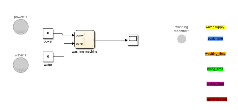
so as we creat an the model as show above,as the inputs as power and the water and the output as scope with the switch is connected to it.
2.as the washing machine stateflow be creat as below-
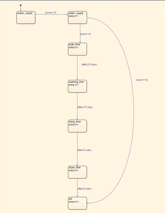
so as the stateflow logic as above
3. if we give input as power = 1,then the only power supply shows on as water in not available so only led is on as blinking an colour
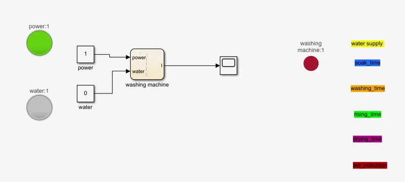
as it indicates an the led as water==0
4.if the water is avilable as input is an set so water supply is on as switch shows the colour yellow.
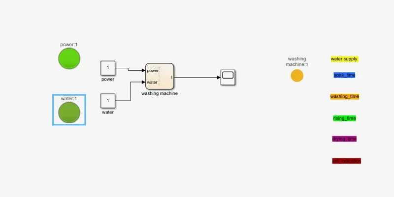
''water supply''
5.as the water supply is available and power also then then the washing machine work is going on sock mode.
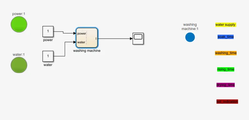
"sock time"
6.after this proper washing time should be on as belows.
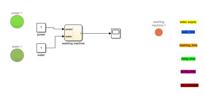
7 after this we get an rising time, drying time and after all the condition we get an the final led condition as the all activity is done then the washing machine is off.
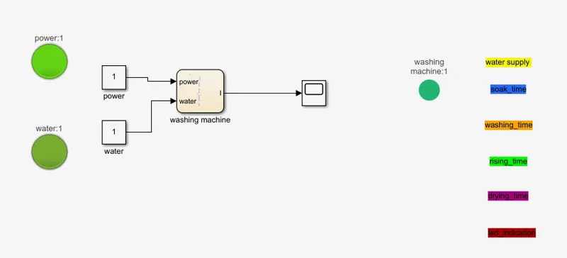
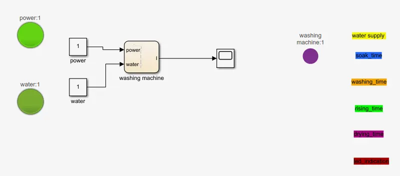
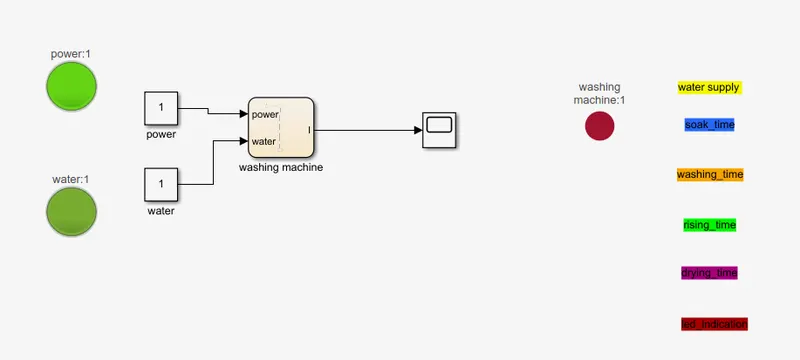
so as all the condition is satisfied and then output is shown into the scope as below
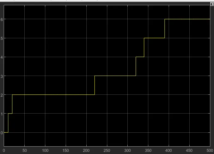
result:- so as from all above we get all the all condition is satisfied as rising, drying and all other condition and the result is shown into the scope as all result is shown into the graph as the inputs and outputs as connected by the switch which show as the result by changing its colours.
Q2.Make a Simulink chart for the “Gear shift” logic as per below conditions:
Speed Range(kmph) Gear
0 to 15 1
16 to 25 2
26 to 40 3
41 to 60 4
Above 61 5
steps:-
1.so as we make an the stateflow diagram as shown into belows stateflow logic of washing machine.
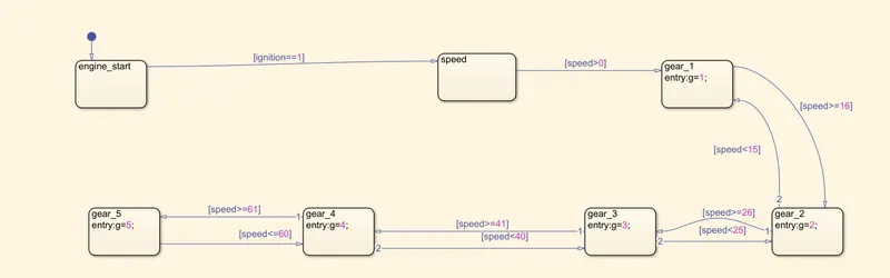
block used and ther function:
1) Chart: A finite state machine is a representation of an event-driven (reactive) system. In an event-driven system, the system responds to an event by making a transition from one state (mode) to another.
2) Two constant: The Constant block generates a real or complex constant value signal.
3) Lamp: for indication.
4) display: For output.
5) Slider: for veriable speed. as we change an the speed we get an the variable speed and the switch shows that which no of gear we should change it.
As per conditions, gear with ther corsponding speed shown in below pics:
as the switch as an output given to it they are on and off according to the change in gear because of change in speed
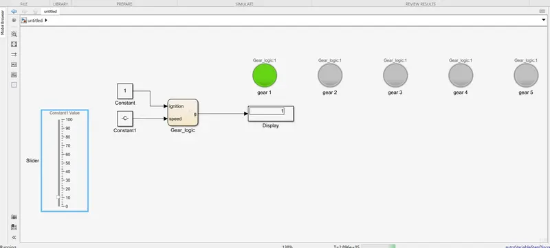
1) speed:0 to 15 with gear no on display and also indicater :- as we put throttle on to the speed as 10 so below 15 as condition is satisfied so it shows as the 1st gear with an indication as green light of 1st gear
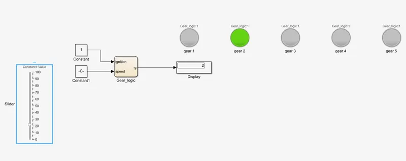
2) speed:15 to 25 with gear no on display and also indicater
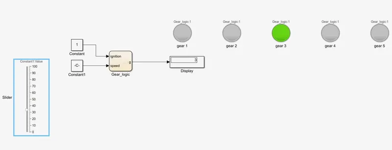
3) speed:25 to 40 with gear no on display and also indicater
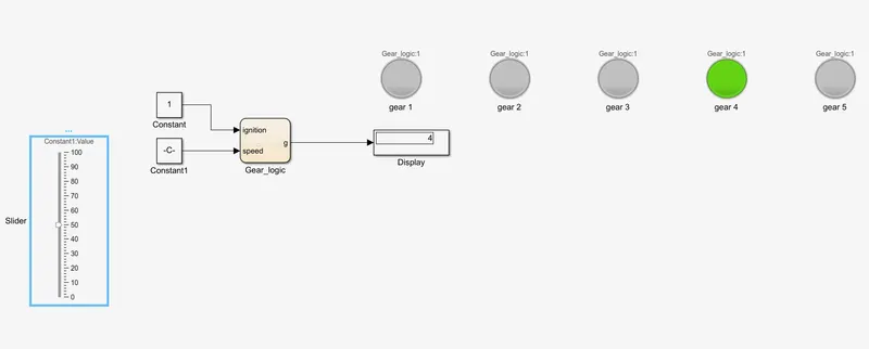
4) speed:40 to 60 with gear no on display and also indicater
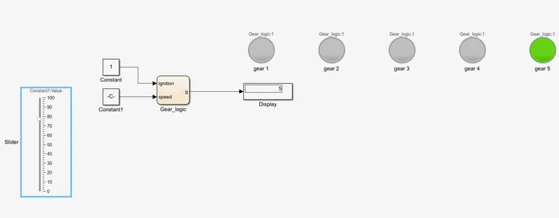
5) speed:60 to 100 with gear no on display and also indicater : so it shows as top gear we want to drive
result:as we creat an the model of vehical gear shifting with an speed is the input.