Week 7 State of charge estimation
Aim:- To study an the BMS close loop harness system.
Objective:-1].Simulate the 3 test cases from harness dashboard
2]What is coulomb counting?
Model configuration:-download the model and opne closeloop BMS harness Dashboard model, as download an the model and extract it 'design and Li-ion battery management algorithm'
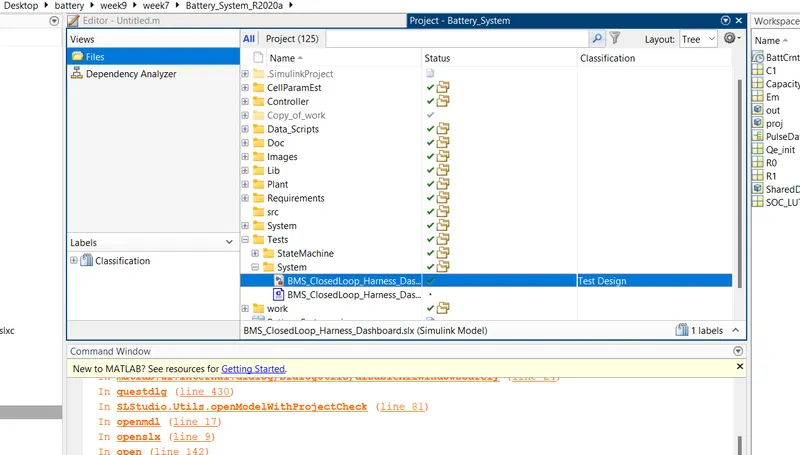
open an the simulink model and model file of an the 'TEST -SYSTEM-BMS_Closeloop_Harness_Dashboard ' model file and the model open like as belows
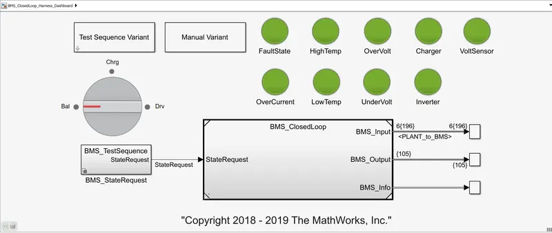
Model Configuration:-"Blocks in model"
1]Dashboard:-
- Test sequence varient:- as it has an the varient of changing an the test cases as consider as an the diffrent drive cycle or the conditions
- Manual varient:- to change an the rotary switch as an the manual varients are the change by an the changing an the varients
- Rotory switch:- it is an nothing but the dashboard or the indicator which shows an the what is actually running as the charging mode, balancing mode or an the driving mode of an the vehicle
- Indicators:- while running an the model their is an the some indicators for an showing thus the faults as showing faulty state as an the high temp,low temp , over voltage ,under voltage, overcurrent ,charger ,volt sensor etc if green then ok and in the case of an the fault condition it is an the red
2]BMS_Closedloop:-its an the main closed loop system which have an the mains 2 parameters as an the a]battery management system electronic control unit and the 2] plant which consist an the battery and its management system. as an the bms closed loop system as the BMS ECU gives an the command to the plant as the charging and the discharging command to the batteryas the state request ios given to the plant unit. the final outputs are the input bms ,output bms ,info ,bms
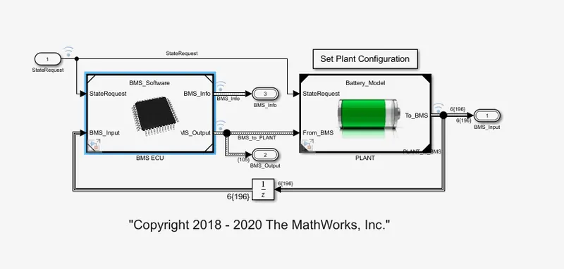
so the bms close loop consist of an the
2.1]BMS ECU:- battery management system electronic control unit
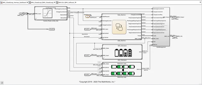
- as they are consist of an the state machine , SOC estimation and the balancing logic
- 2.1.1] current power limit calculations:- it has an the some calcualations according to the temperature and the cell voltage inputs as it contains as shown belows
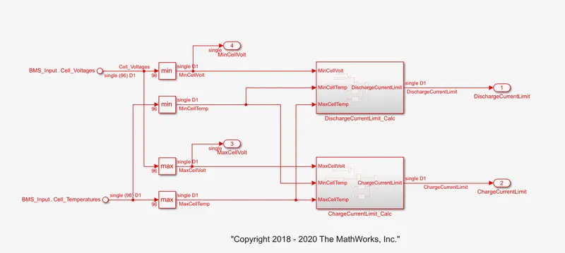
- as it has an the input as the cell voltage and the temperature limits as the maximum and the minimum,as well as by the charge current and discharge current limits it get an the final value of charge and the discharge currents
- Input,s;- voltage and the temperature are the inputs and outputs:-max and min voltge of cell and the charge and discharge current of the cell.
- 2.1.2]state machine algorithm
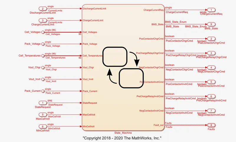
- as an it has an the no of inputs as the shown above as well as the no of outputs in this case as well as the state transitions are below as
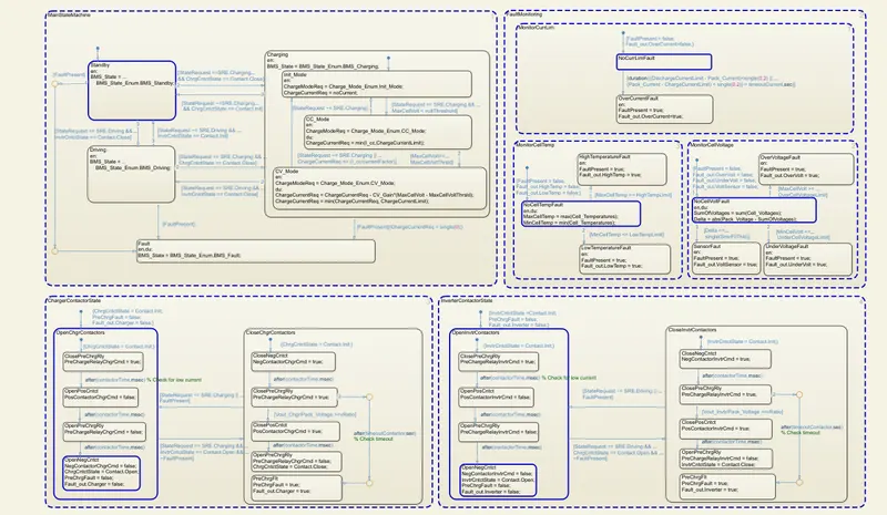
- this state transitions only for the charging discharging with an the control of voltage and the current. fault monitoring, contactor state as well as the invertor state are shown above as these output values will be fed to the bus management.
- 2.1.3]state of charge estimation:- as all we know that the state of charge is important to avoid the overcharge and also overdischarge also so to avoid it we required an the soc estimation
- Coloumb counting:-as an during counting an the soc we need to count an the coloumb capacity
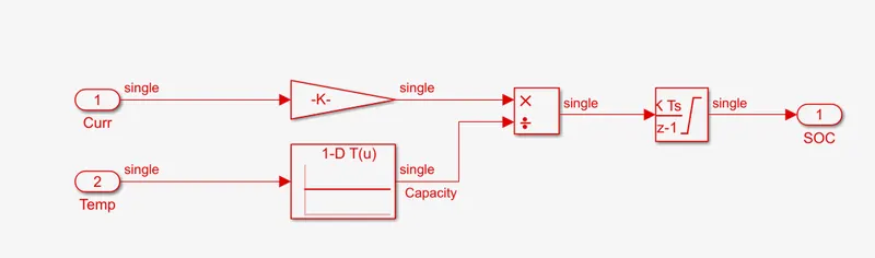
- as well as the soc estimation by the ekf and ukf diffrent kalmans filters as soc estimation takes an the input from the BMS inputs and gives the SOC outputs
- 2.1.4]Balancing logic:-as an from the below it has an the state logic of the BMS state ,maxvtg,minvtg,BMS input as 4 inputs and the baalance command to bus management is the output
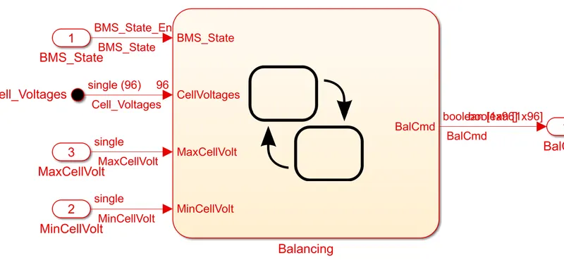
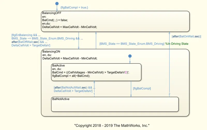
- this is an the balancing logic for the battery
- 2.1.5]Bus management:-
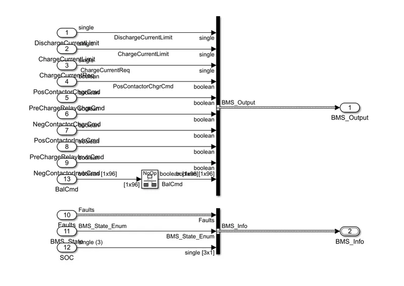
- as all the outputs of cell balancing, soc estimation, and the stste machines are the inputs and the output to the plant by this module.by this we can get an the actual battery management system as the soc, max voltage ,max temp etc.
PLANT MODULE:-
- plant module it is an nothing but the contains of the battery pack as well as the precharge circuit and the charger and load module .
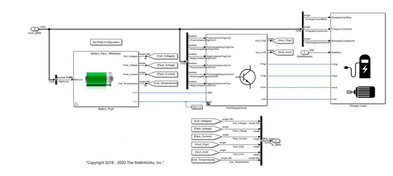
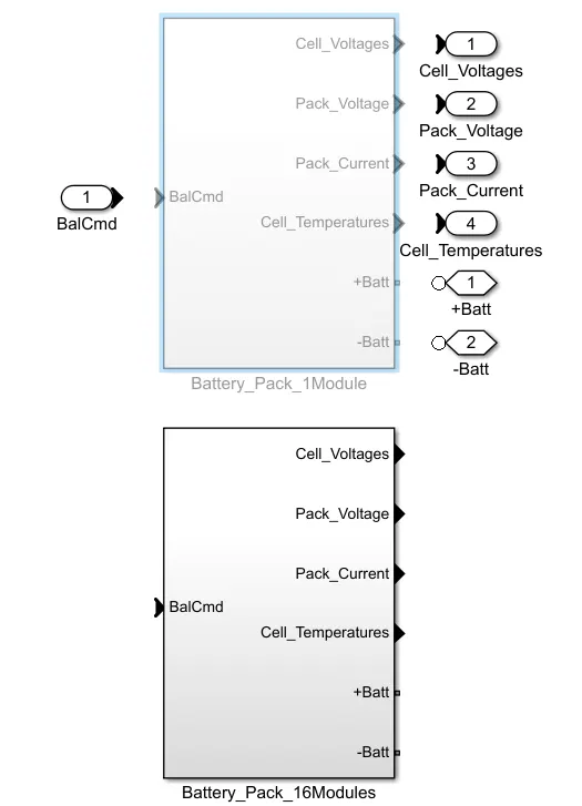
- 3.1.]Battery pack configuration:- as an the configuration of an the module is shown in above as the so it has an the battery configuration as the 1.]1module 6cells 2.]16module =16 x 6=96 cell connected in series we are choosing an the 1 module instead of the 16 due to the simulation time management
- input:- it has only an the soc input or bms input and the output are as the no of cells are connected as consider as an the voltge and temperature are the important factor
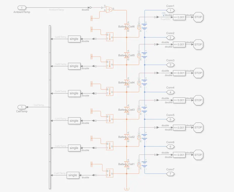
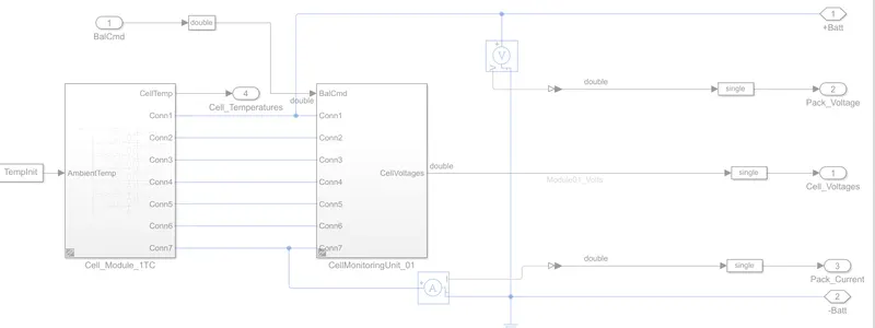
- as it is an the simple 6 cell module which has an the temperature input which haves an the temperature sensor and after it senses it gives as an the output but of the it has the less value of comparison then it stops to discharges
- as by the voltage and current controlled sensor we can get the actual voltage and the current as well as an the pack parameters as an the ouput also which are at the battery pack output connected as an the plots as cell voltge ,pack voltage ,pack current ,pack temperature etc.
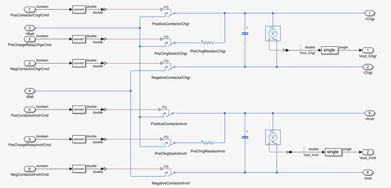
3.2]Precharge circuit:- as to charge the battery their is required an the ckt calleec as the precharge circuit which has an the charge and the invertor command with an the contactor an be closed or open through it as well as for an the inputs it has some signals taken from an the BMS as all we know that
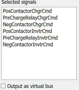
- as this above are the signals required for an the precharge circuits. as it has nothing but the only as the switching action with an the precharge resistors with an the positive nagetive and precharge switch can be employed as the -ve ,precharge and then +ve contactor. output as the vout charge and vout invertor.
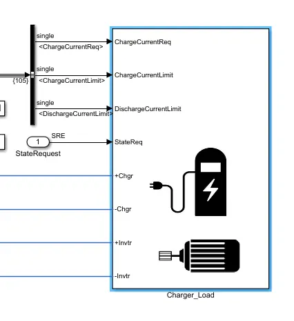
3.3]Charger-load:- as an it has an the some inputs from an the BMS and the
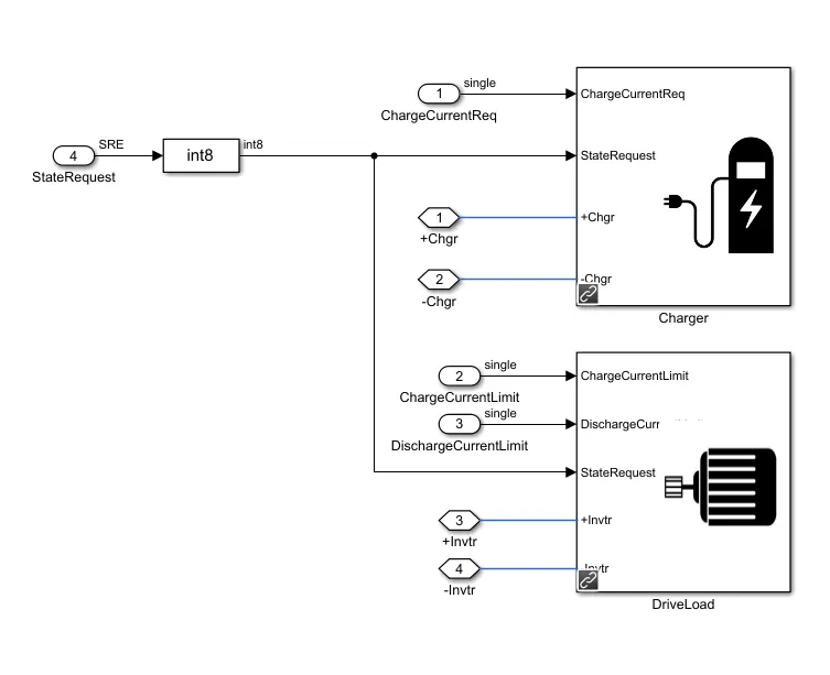

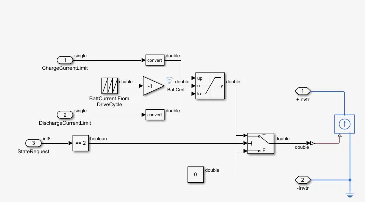
Charger ckt Drive load ckt
- as from an the above ckt as all we know that the battery as charging and the load ckt connected as the above. as the charger ckt it have an the constant current input but in the case of an the load it has an the drive ckt based current as shown belows.
- so we can run the model with an the some diffrent test cases as the drive cycle is the same as the output currents
case 1:-to run an the 3 test cases an d the result will be an compare with an the close loop bms control
Test case 1:- as from an the dialogue box test sequence varient as shown belows
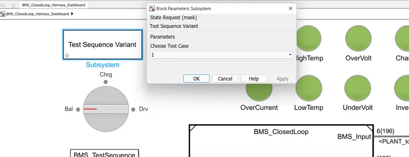
as we can choose the test case as an the 1 which has an the consist an operation as the belows
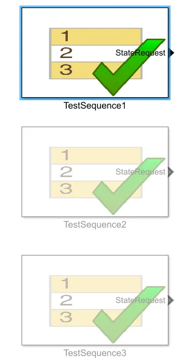
as well as the selection consist changes in the BMS state request subsystem as,
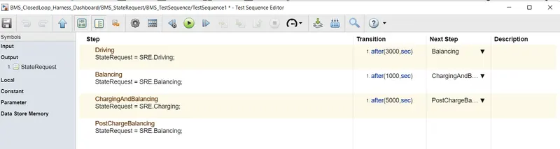
as from an the above we get that the test sequence editor as an the
- driving first for 3000 sec
- after the driving we start balancing for next 1000sec
- then charging and balancing after it
- post charge balancing occure till the simulation runs.
results:-
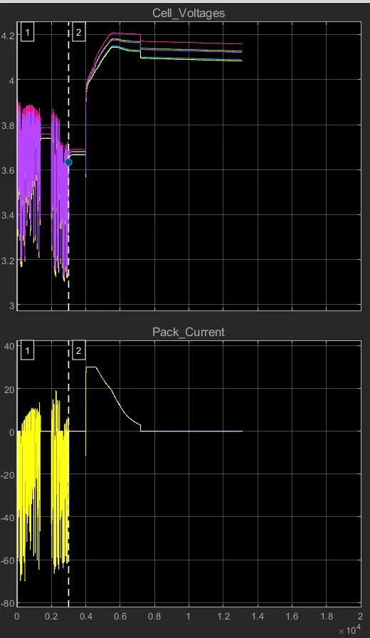
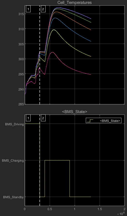
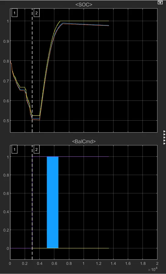
- as an the first 3000 sec 6 cell will be an at the drive mode as an the cell discharge occurs at that time so at that time the
1]Drive mode:- 0 to 3000sec
- voltage:-so the first 3000 sec the battery will be discharge due to the drive cycle and then they are the balancing state so at an the driving mode voltage will be drop an at the 3.9 to 3.1 of all cells
- Current:-as the current also to be flow from the -70 to 10 ampere due to discharge its current will be -ve
- temperature:- as an due to the diffrent cell position or placement as the during drive mode the centre cell will be at an more heated so the temperature of these cell will be very much
- BMS state:- as an at the starting due to the driving mode it shows at the drive mode,
- SOC:- state of charge reduced from an the 80 to 50% as due to the drive cycles
- BAL_cmd:- as an it has an the balance command so at an the drive their is the drive command so their is the bal cmd will be inactive
2.Balancing mode:- 3000 to 4000sec
- voltage:-so the 3000 to 4000 battery will be try to balancing the circuit at an 3.7v
- Current:-as the current is not flow in this ckt due to no load condition
- temperature:- as an due to the diffrent cell position as in case of the balancing it try to the reduced the temperature.
- BMS state:- as an due to the balancing mode bms state is standby mode
- SOC:- state of charge will be constant at that time it affect only due to self discharge
- BAL_cmd:- as an it has an the balance command so balanced command will be active.
3]charge and balancing mode:- 4000 to 9000sec
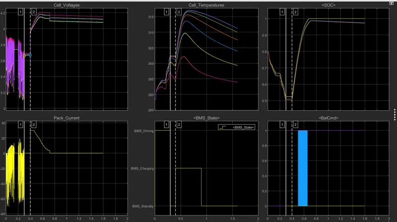
- voltage:-so the 4000 to 9000 battery will be try to balancing with charing the circuit at an 4.1v
- Current:-as the current is flow in this ckt due to no load and charging condition
- temperature:- as an due to the diffrent cell position as in case of the charging temperature it try to the increases and reduce during balancing the temperature.
- BMS state:- as an due to the charging mode bms state is chargingmode
- SOC:- state of charge will be fully charged at that time it affect only due to self discharge
- BAL_cmd:- as an it has an the balance command so balanced command will be active.
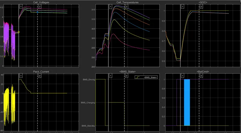
3]post charge balancing mode:- 4000 to 9000sec
- voltage:-so the 9000 to 20000 battery will be try to balancing with charing the circuit at an 4.1v
- Current:-as the current is zero in this ckt due to no load and charging condition
- temperature:- as an due to the post charge balancing mode temp reduces very fastly
- BMS state:- as an due to the charg post balancing mode bms state is standby mode
- SOC:- state of charge will be fully charged at that time it affect only due to self discharge
- BAL_cmd:- as an it has an the balance command so balanced command will be active.
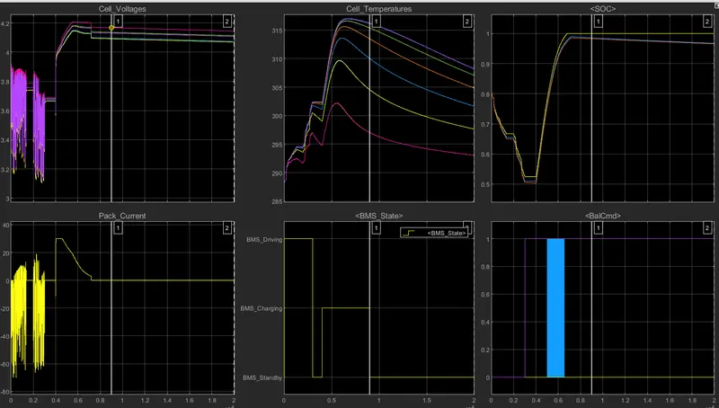
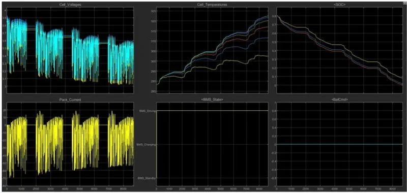
Test case 2:- as an the state case request changes to 2 as following drive cycle we can choose an the test case as the 2
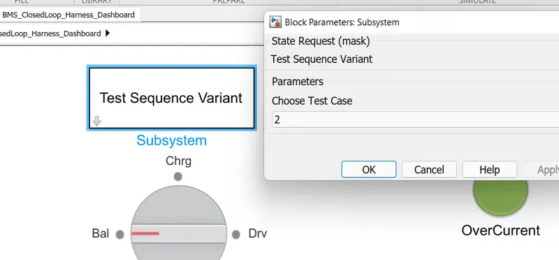
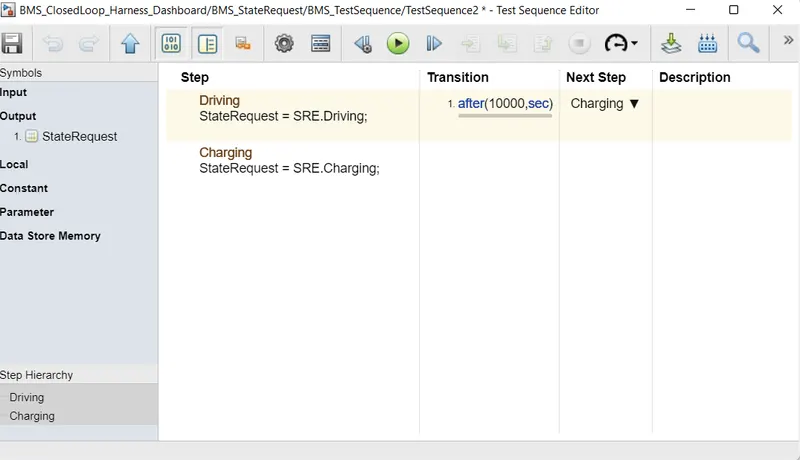
- so as an the test case we get that at an the ataring model drive at an 10000sec and then the it starts charging the battery. so the results will be an obtain as the belows
- it has an only the 2 modess as an the driving and other is the charging mode.
1 Driving mode:- 0 to 10000 sec
- voltage:-so the 0 to 10000 drive mode so voltage will be reduces rapidly. fro 3.9 to 3.05
- Current:-as current is also -70 amp and some extend 10 positive
- temperature:- as an due to the diffrent cell position as it varies from 288 to 302k.
- BMS state:- as an due to the driving mode bms state is driving state
- SOC:- state of charge will be reduces rapidly at that time.
- BAL_cmd:- as an it has an the balance command so balanced command will be inactive due to drive mode.
2 Charging mode:- 0 to 10000 sec
- voltage:-so the after an the 10000sec as battery is fully discharges then the we can start charging
- Current:- as due to the charging current is always positive
- temperature:- as an due to the diffrent cell position as temperature reducing
- BMS state:- as an due to the driving mode bms state is driving state
- SOC:- state of charge will be increases rapidly at that time.it is an the
- BAL_cmd:- as an it has an the balance command so balanced command will be active due to charge mode.
Test case 3:- now select an the test case 3 in the sequence varient dialogue box as shown below
these test cases consider an the charging for an entire duration of the time
as well as all the indicators are the green means their is no any fault in the conditions as well th plots are the belows
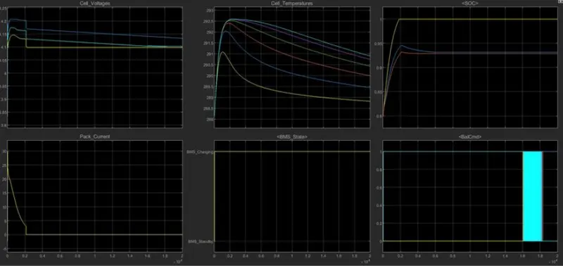
1 Charging mode:- start to end
- voltage:-so as the initially cell voltage rises from an the 3.9 to the 4.2 and then by balancing it is at the 4.15,as the cell no 1 rises from an the 3.85 to 4.15
- Current:- as due to the charging current is always positive as an the current rising from an the 0 to 30 amp and starts to reducing at an the 2.5ampere at an 2000sec,at an 2000 sec fully charged to 100% and after an fully charge cutoff will be operated as
- temperature:- as an due to the diffrent cell position as temperature increases heat upto full charge and then temperature reduces to ambient temperature as shown in the plot after an the cell is fully charges then the temperature will be reduced
- BMS state:- entire pack will be an at charging mode so stste is the BMS Charging mode.
- SOC:- state of charge will be increases but the it has an the much more diffrence between the cells as an at the 20000sec pack will be an the fully charged as an the actual charge is arround an the 93% as full charge shown by the UKF and EKF techniques.
- BAL_cmd:- here is an the cell no 6 and the 2 are starts balance with an the end of simulation
Conclusion :- as from all the test cases we annalyse the performance of the BMS on varies factors and parameters.
B].What is coulomb counting? Refer to the above model and explain how BMS implements coulomb counting for SOC estimation.
- stste of charge it is an nothing but the rate of available capacity to the maximum capacity when a battery is fully charged describes the remaining capacity in percentage.
- and to find the soc we are using an the coloumb counting method as the coloumb counting measures an the discharging current or ah capacity of an the battery and integrates an the discharging current over the time in order to the estimate an soc discharging current=previous estimated soc(SOC(t-1))
SOC(t)=SOC(t-1)+(I(t)*delta t)/Qn
- modified coloumb counting:-in this technique discharge current is corrected with an the functional and the corrected current is found out for accurate soc estimation
Ic(t)=k2I(t)^2 + K1I(t) +K0,
- where the k0,k1,k2 are all the constants
- SOC Estimation in BMS models:-
- as it is in the bms close loop - BMS ECU - SOC Estimation - coloumb counting
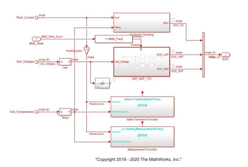
- here as an thedischarge current willl be at given to gain with an the 1/3600 to converts to ah capacity
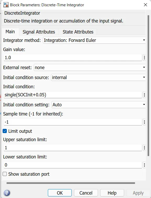
- the value is divided by capacty due to change in temperature and when it is integrated with an gain value of 1 with sample time -1 as we are using diffrent integrator
- saturation limits from 0 to 1 and multiply t to get an the gain in 100%