Week-7 Challenge: DC Motor Control
1. A. Explain a MATLAB demo model named ‘Speed control of a DC motor using BJT H-bridge’.
-------------------------------------------------------------------------------------------------------------------------------------------------------------
ANS:
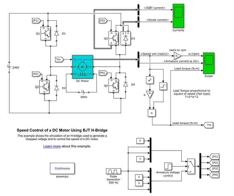
Use of component-
1.Voltage sorce. 2. BJT with diode(H-Bridge) 3.DC Motor 4.Pulse Generator circuit
Input Power circuit:
As a input circuit we use a DC input 240 V voltage .
H-bridge circuit:
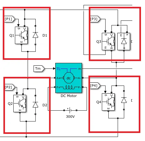
In BJT circuit we use 4 nos with 4 nos diode across each BJT .with ron resistance 0.001 ohm and forward voltage is 1 volt.
Motor Section:
Here the External power suply from another DC voltage sorce use where the voltage sorce is 300 V.The motor is 5 HP and 240 V 1750 RPM.
Pulse Generator circuit:
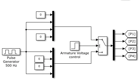
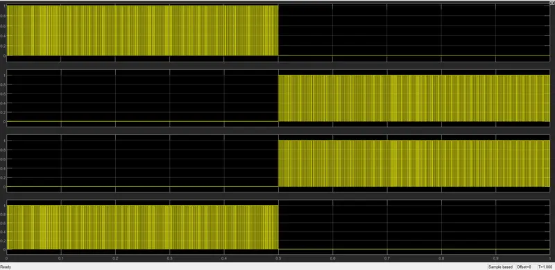
For gate pulse signal we use one no pulse genaretor And two combinne of input gate input puls arrangement.Where the switch used for select the GTA pare firing pulse which switch oparate or controled by the armature voltage control block.basically the pulse genarate 500 Hz and 1 V volt amplitude signal.For two arrangement for Q1 ,Q4 and another is for Q2,Q3 selected by the switch block and the switch change its state with respect the Armature voltage control block with 0.5 stape time.
Mechanical Load section:
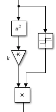
For design the mechanical load we user a equation T=K*w^2 with help of one squre block one no step input block for w value one no gain block and a product block for make the equation.
Oparation:
In basic fundamental case the DC motor run in 240V DC voltage but in case of control the mor speed there is no chance only way to control the speed is to control the Motor input voltage and that the only possible when we regulate the voltage thats why there need any type of regulator but in case of linear regulator there the main problem is IR loss or heat losses that why we prafere the switching controller.In this circuit we use the BJT switching component for main control component and for control the voltage we use 4 nosBJT for suply the control voltage in motor.
this also use full bridge inverter .And the time periode of pulse decide the voltage level of suply and the pulse decide the pulse with regulation.
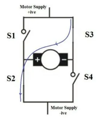
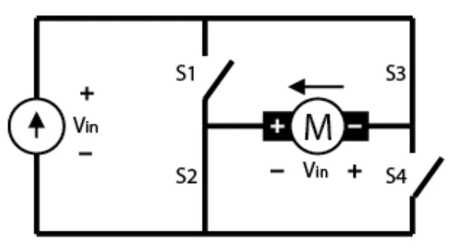
For h-bridge circuit the Q1 and Q4 IGBT close then the current flow through S1 to motor to S4 and then close the circuit.
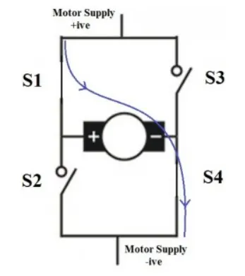
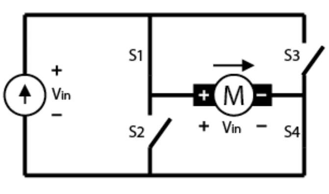
For h-bridge circuit the Q2 and Q3 IGBT close then the current flow through S3 to motor to S2 and then close the circuit.
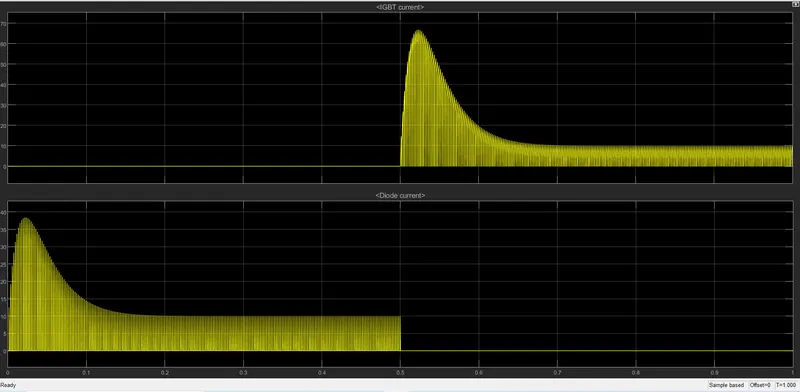
The IGBT current and diode current plot are below-
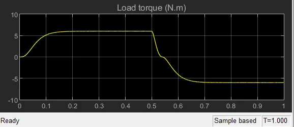
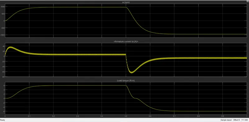
Speed armature current Speed and load torque plot are given bilow-
B. Comment on the armature current shoot-up from the scope results.
ANS:
Due to DC motor the starting case the motor is at stop condition so the stetor and rotter speed diffarent or sleep is 1 so thats why the At the starting condition motor take huge amount of current for match the speed of rottor and stator becouse at the starting condition the torque is is high and we know
torque =K*I
where the k is armature constant
so this relation shows that at starting condition when torque is high then the current also high and when the torque become or sleep become stable then the system become take normal current .
and the shotup current range depend on input firing duty cycle.
if we decrease the duty cycle then the input current also reduce.
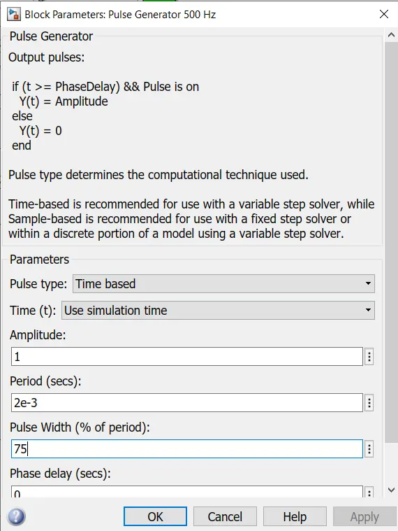

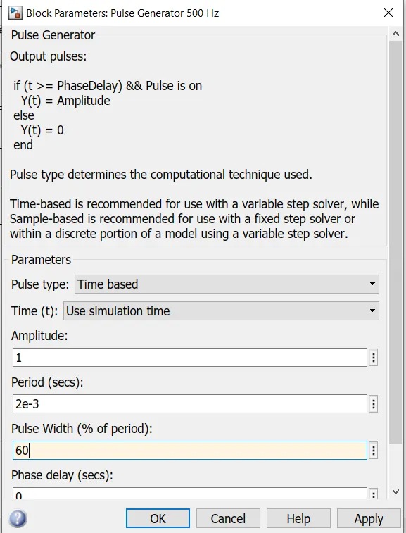

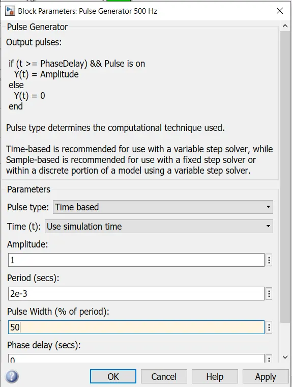

From this comperison we found that when we decrease the dutycycle then the system become stable the current shootup amount reduce.
becouse when we change the input duty cyle then also we limit our input current.
C. Refer to the help section of ‘The Four-Quadrant Chopper DC Drive (DC7) block’. Compare it with the H-bridge model.
ANS:
H-Bridge:
In H-bridge we use 4 nos semiconductor switch(IGBT) to control the voltage and currant .Switching Q1 and Q4 switch we aply forward direction voltage and current in another way we switching the Q2 and Q3 we genarate revarse voltage and current for forward mode and reverse regenartive braking mode.Control the switch we can change the direction of the motor rotation.
DC7 Block:
In case of DC7 block there is a already the bridge section and the pulse section preasent in the block and the mainly the control with two reffarance one is PI current controller and another is PI Speed control .With those two reffarance the system work or the output power control in the system.
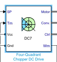
There the DC input need and for feed back speed and torque need and the as output motor control out put.
1. In case of H-bridge the only reffarance for control the voltage is the pulse width
and in case of DC7 block we can control by giving the speed refarance orcurrant refarance.
2.In case of H-bridge IGBT control by pulsewith modulation technich.
Armature voltage control by IGBT converter by two nos PI regulator.
-------------------------------------------------------------------------------------------------------------------------------------------------------------
2. Develop a 2-quadrant chopper using simulink & explain the working of the same with the relevant results. (Refer to article - Multiquadrant operation of motor )
-------------------------------------------------------------------------------------------------------------------------------------------------------------
ANS:
Two -quardrant type-A chapper ,or Type C chopper:
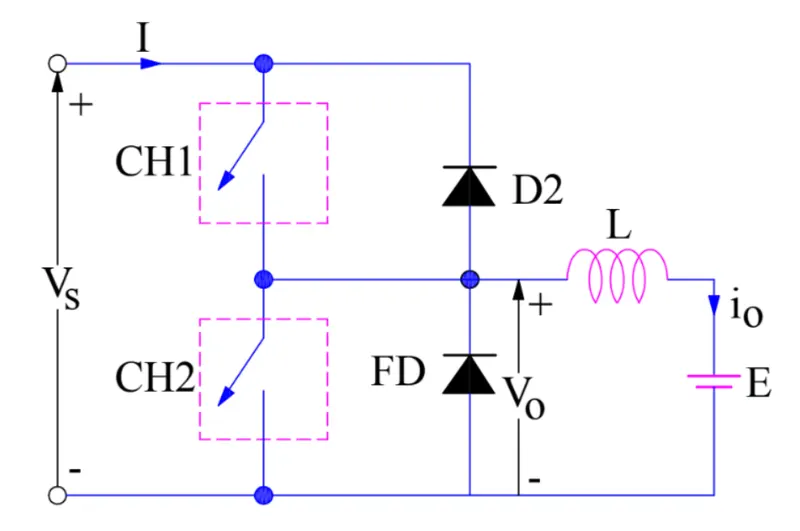
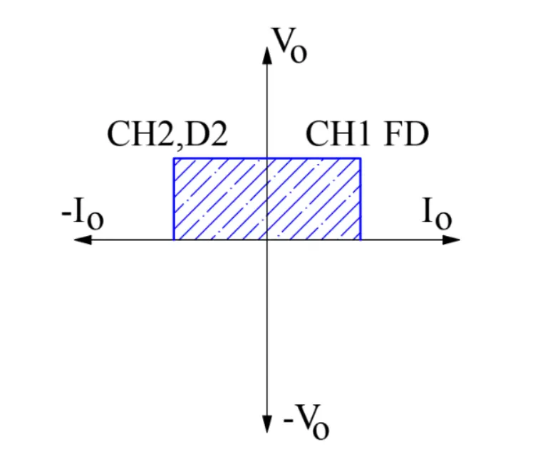
This type of chopper is obtain by connecting type A and Type B chopper in paraller as shown in figure the Output voltage alwase positive becouse of the presence of FD across the load.when chopper CH2 is ON or FD is conducts output voltage V0=0and in case chopper CH1 is on or diode D2 conducts, output voltage V0=Vs,The load current i0 can,however reverse its direction .Currenrt i0 flow in arrow direction.load current is posetive when CH1 is on and FD conducts.Load current is negative CH2 is on and D2 oparate togather as type B chopper in second quadrant. Avarage load voltage alwase positivebut avarage load currant maybe positive .therefore ,power flow may be sorce to load or load to sorce.
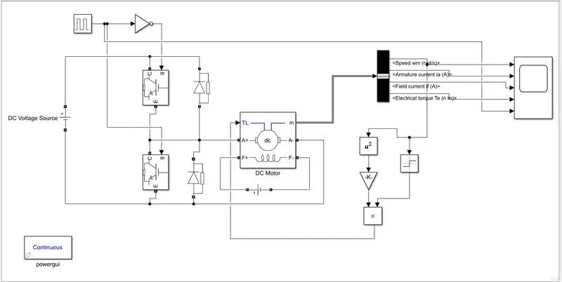
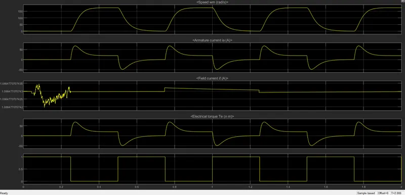
two quadrant chopper
where we use 230 volt DC voltage source for input,two IGBT for switching device DC motor which actually input 240V and the field voltage is 300V and the switching pulse duration is 0.5 sec and pulse weth is 50%.
-------------------------------------------------------------------------------------------------------------------------------------------------------------
3. Explain in a brief about operation of BLDC motor.
------------------------------------------------------------------------------------------------------------------------------------------------------------
ANS:
Every Dcmotor have brush to suply the voltage in stator or rotar but in case of BLDC motor there is the permanent magnet to make the stator The stator coil is wounded with coils,they are statiopnary but producing variable DC voltage for rotating the permanent magnet as changing the magnetic field stator windings.
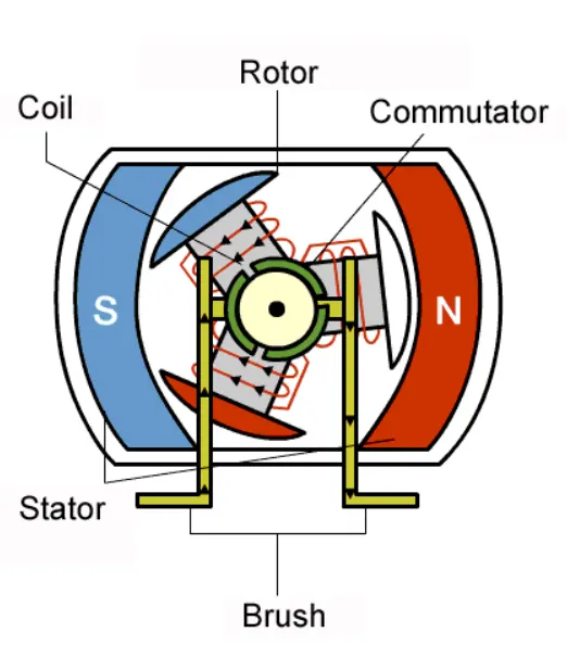
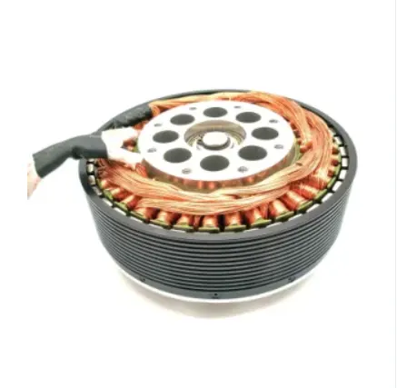
A BLDC motor with three coilon the stator will have six electrical wires (two of each coil)extending from these coil.In most implementations three of these wire will be connected internally,with the three remaining wires extending from the motor body.
Wiring the BLDC motor case is more complicated than simply connecting the power cell's positive and negative terminals.we will look more closely at how these motors work in the second sessiopn of this series.
BLDC Motor:
we can consider three winding terminal are comming out as U,V,W and their another ends are connected in single point as shown.The angle shift between two coil makes 120 degree.
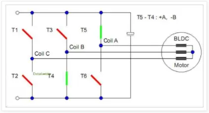
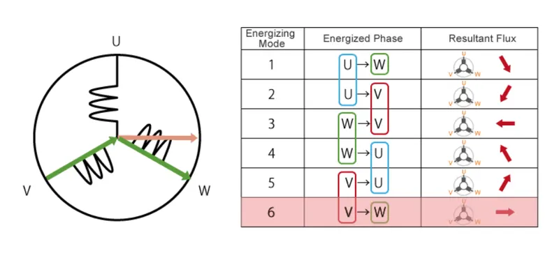
The current moves U to W makes magnetizing the coils attack the rotor consistng of permanent magnet makes momentas shown above to align with the result v.
North pole of magnet towards arrow of resultant arrow.
Rotation is maintained by continually switching the flx so that the permanent magnet is constantly chasing the rotating magnetic field induced by the coil.In the other word ,energizing of U,V,W mustbe continuaslly switched so thatthe permanent magnet is constantly chasing the rotating magnetic field induced by the coil.
Advantage of BLDC:
One big advantage is efficiency ,as these motors can control continuously at maximum rotational force.
Even small BLDC motor can deliver considerable power
BLDC motor can be controlled ,using feedback mechanisms to delivery precisely the desired torque and rotation speed.