Week - 4
- Implement control logic of a “washing machine” using Stateflow as per given sequence:
- If the power supply is available, the system gets activated
- If the Water supply is not available, stop the process & indicate through LED
- Soaking time should be 200s followed by Washing time of 100s.
- Then rinsing happens for next 20s & dryer runs for 50s
After all the processes have completed turn on the finished LED
Ans:
Circuit:
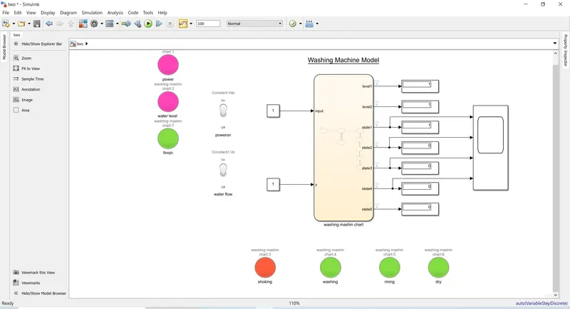
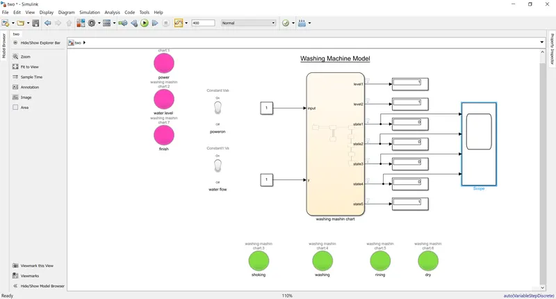
At the washing mashine system there is foure prossece like Soking,Washing,rinsing and drying.
here we use two swtich for change the state of power and water level enable or disable.
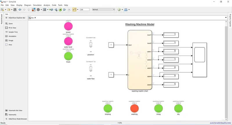
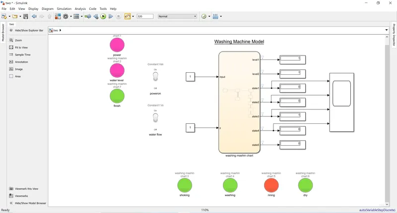
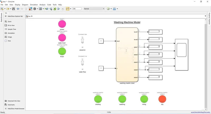
use seven lamp indicator for examine the result whose green state mean nutral and red state mean enargige.
also we use a scope for examine the out put responce.
Use display for examine the state with time respective.
s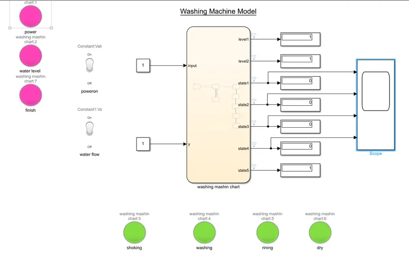
Flow chart:
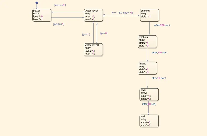
For controlling the system we use the logic which is actually represented by flow chart which displaing at circuit.
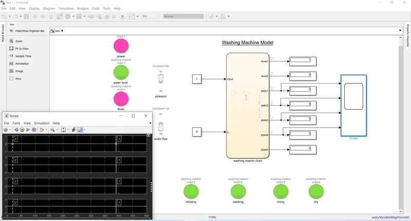
when water level is low the system become in lock position no stape improvement.
At this condition no state activated.
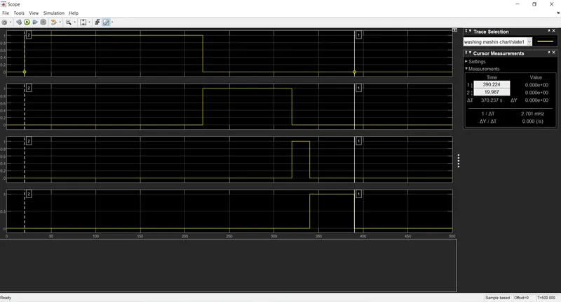
After 100 sec:
After 220 sec:
After 320 sec:
After 340 sec:
After 400 sec:
Final result:
total working periode is 370 sec as per our logic circuit.
2. Make a Simulink chart for the “Gear shift” logic as per below conditions:
Speed Range(kmph) Gear
0 to 15 1
16 to 25 2
26 to 40 3
41 to 60 4
Above 61 5
Give speed input while the simulation is running & display the gear number.
Answer:
Theory:
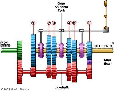
According of the road condition the veical change the gear ratio for smooth driving where the gear while edious value change with chane of vaical speed fo maitain the torque.
Each gear level has its own redious gear which contain a gear box connected with wheel of the car and change with speed level for maitain the smooth driving or smooth engine oparation.
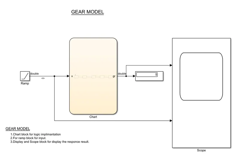
In the gear circuit we use a chart box for logic control and here the logic which is actually use for controlling the gear accoding to speed.
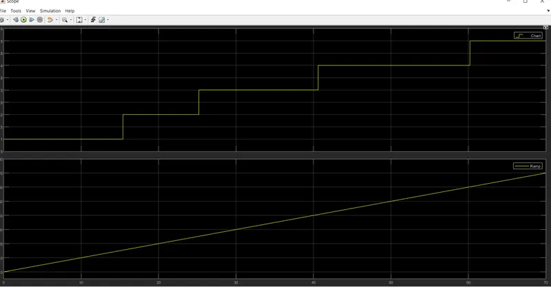
the bbasic input is speed which denoted a ramp box which is actually increase the speed linearly from 0 to 60 above and the out put after
control by the chat box controller shows the result at scope. Each box indicate the gear level which acthually increase the gear parameter
when the perticular gear oparate.
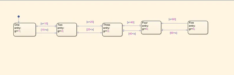
Clearly the result shows that when the input speed increasing linearly then the response change accoding to logic.