Project 2 Adaptive Cruise Control
Adaptive Cruise Control (ACC)
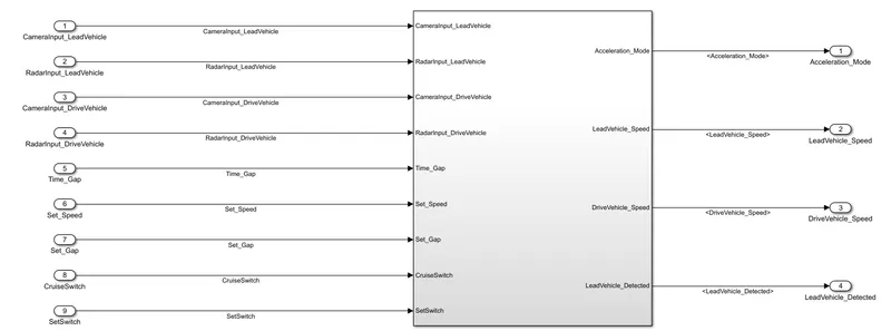
We use input signal:-
1.CameraInput_LeadVehicle
This is the input which confirm the lead vehical existance or identification.
2.RadarInput_LeadVehicle:
This is the input of the lead vehicals position or distance.
3.CameraInput_DriveVehicle:
This is the signal which confirm the Drive vehicals position in the road.
4.RadarInput_DriveVehicle:
This is also confirm posithion signal of the Drive vehical.
5.Time_Gap:
This signal is indicate or set the time value for delay.
6.Set_Speed:
This is the signal where we set the speed value.
7.Set_Gap:
This is the set value which indicate how much distance dive vehical maitain from lead vehical.
8.CruiseSwitch:
This is the signal which enable the Cruise control mode.
9.SetSwitch:
This is the input for set the control type.
We use outputs are -
1.Acceleration_Mode:
This is the data which give the Acceleration mode in our case total 6 mode available.
2.LeadVehicle_Speed:
This is the value wher its give the Lead vehical's speed.
3.DriveVehicle_Speed:
This is the value which gives the drive vehical speed.
4.LeadVehicle_Detected:
This signal gives lead vehical existancy.
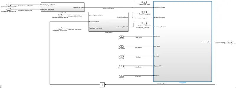
Lead Vehicle:
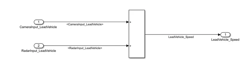
Drive Vehicle:
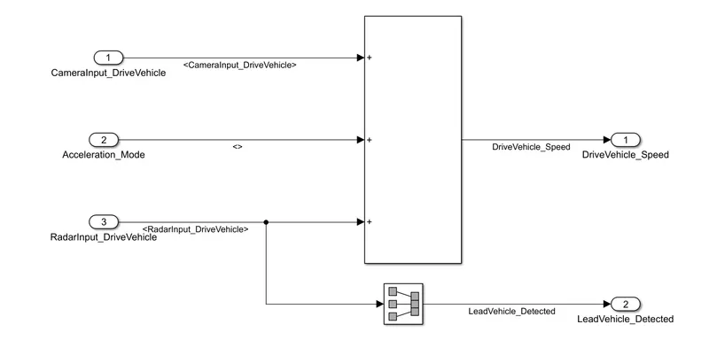
There is three mode for ACC oparetion:
1. ACC OFF MODE
2. ACC STANDBY MODE
3. ACC ON MODE
In the ACC on mode we found Adaptive Cruise control Algorithm,
Adaptive Cruise Control Algorithm:
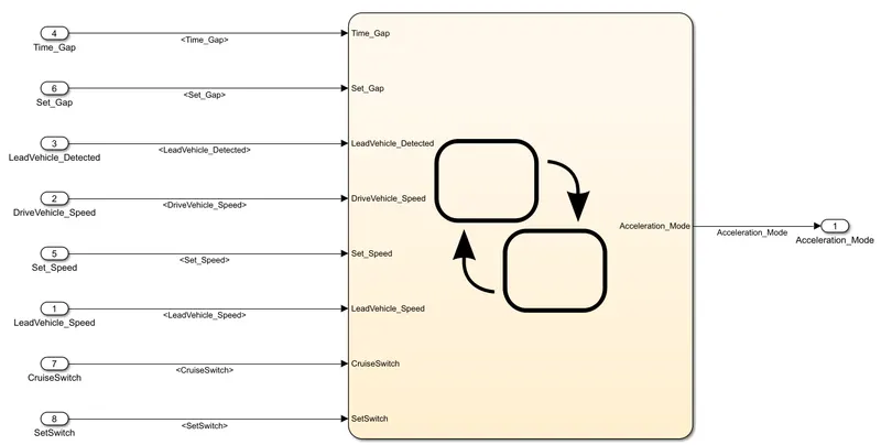
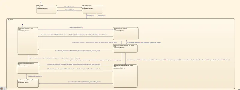
For Adaptive Cruise Control Algorithm we found 6 nos mode :
MODE1: LeadVehicle_Detected_Follow (Default)
Algaritham:
This is the default sub state inside ACC ON MODE state. Output signal Acceleration_Mode is equal to 2.
-
- Condition to transit from LeadVehicle_Detected_Follow to LeadVehicle_Not_Detected; Input signal condition LeadVehicle_Detected == 0.
- Condition to transit from LeadVehicle_Detected_Follow to LeadVehicle_Speed_lessthan_Set_Speed; Input Signals condition (LeadVehicle_Detected == 1) && (LeadVehicle_Speed < Set_Speed) || (Time_Gap < Set_Gap).
MODE2: LeadVehicle_Not_Detected
Algaritham:
Output signal Acceleration_Mode is equal to 1.
- Condition to transit from LeadVehicle_Not_Detected to LeadVehicle_Detected_Follow; Input signals condition [(LeadVehicle_Detected==1) && (DriveVehicle_Speed == Set_Speed) && (LeadVehicle_Speed >= Set_Speed) && (Time_Gap >= Set_Gap)]
- Condition to transit from LeadVehicle_Not_Detected to LeadVehicle_Speed_lessthan_Set_Speed; Input signals condition [(LeadVehicle_Detected == 1) && (LeadVehicle_Speed < Set_Speed) || (Time_Gap < Set_Gap)]
MODE3: LeadVehicle_Detected_Resume
Algaritham:
Output signal Acceleration_Mode is equal to 3.
- Condition to transit from LeadVehicle_Detected_Resume to LeadVehicle_Detected_Follow; Input signals condition [(DriveVehicle_Speed == Set_Speed) && (LeadVehicle_Speed >= Set_Speed) && (Time_Gap >= Set_Gap)]
- Condition to transit from LeadVehicle_Detected_Resume to LeadVehicle_Not_Detected_Resume; Input signal condition LeadVehicle_Detected==0.
- Condition to transit from LeadVehicle_Detected_Resume to LeadVehicle_Speed_equal_Set_Speed; Input Signal condition [(DriveVehicle_Speed < Set_Speed) && (LeadVehicle_Speed > DriveVehicle_Speed) && (Time_Gap >= Set_Gap)]
MODE4: LeadVehicle_Not_Detected_Resume
Algaritham:
Output signal Acceleration_Mode is equal to 1.
MODE5: LeadVehicle_Speed_lessthan_Set_Speed
Algaritham:
Output signal Acceleration_Mode is equal to 4.
- Condition to transit from LeadVehicle_Speed_lessthan_Set_Speed to LeadVehicle_Not_Detected; Input signal condition [(LeadVehicle_Detected == 0) && (DriveVehicle_Speed == Set_Speed)]
- Condition to transit from LeadVehicle_Speed_lessthan_Set_Speed to LeadVehicle_Speed_equal_Set_Speed; Input signals condition [((LeadVehicle_Speed*1.25>=DriveVehicle_Speed) && (LeadVehicle_Speed * 0.75<=DriveVehicle_Speed)) && (DriveVehicle_Speed < Set_Speed) && ((Time_Gap<=1.25*Set_Gap) && (Time_Gap >=0.75*Set_Gap))]
MODE 6: LeadVehicle_Speed_equal_Set_Speed
Algaritham:
- Output signal Acceleration_Mode is equal to 5.
- Condition to transit from LeadVehicle_Speed_equal_Set_Speed to LeadVehicle_Not_Detected_Resume; Input signal conditions is [(LeadVehicle_Detected == 0) || (DriveVehicle_Speed <= Set_Speed)]
- Condition to transit from LeadVehicle_Speed_equal_Set_Speed to LeadVehicle_Detected_Resume; Input signal conditions [(DriveVehicle_Speed < Set_Speed) && (LeadVehicle_Speed > DriveVehicle_Speed) || (Time_Gap >= Set_Gap)]
- Condition to transit from LeadVehicle_Speed_equal_Set_Speed to LeadVehicle_Speed_lessthan_Set_Speed; Input signals conditions [(LeadVehicle_Speed<Set_Speed) && (LeadVehicle_Speed<DriveVehicle_Speed) || (Time_Gap == 0.75*Set_Gap)]
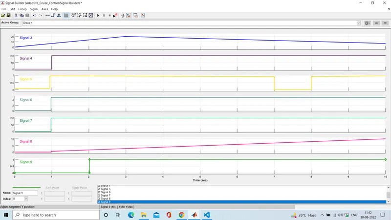
TEST:
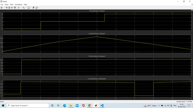
We make a random signal input data and we analyse the system
The System:
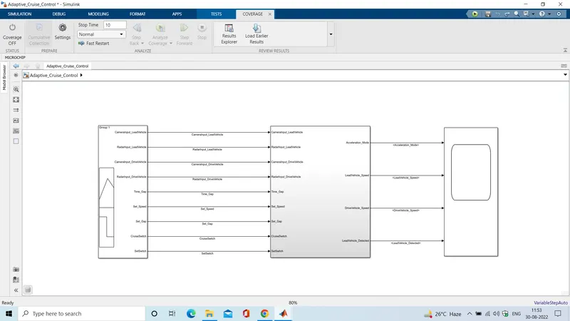
Corresponding we found the result where the accelaretion zero two and four works.
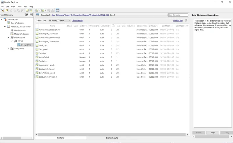
Data Dictionary :
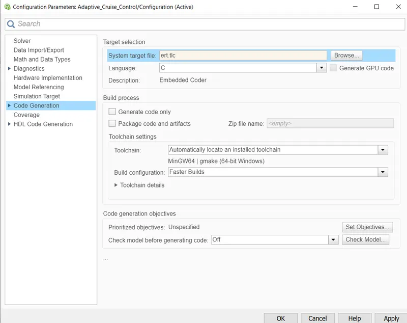
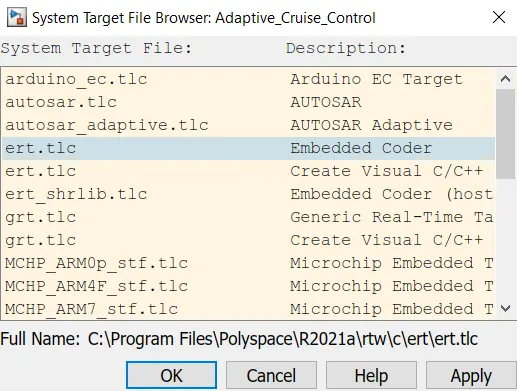
This is the configuration setting window for code genaration:
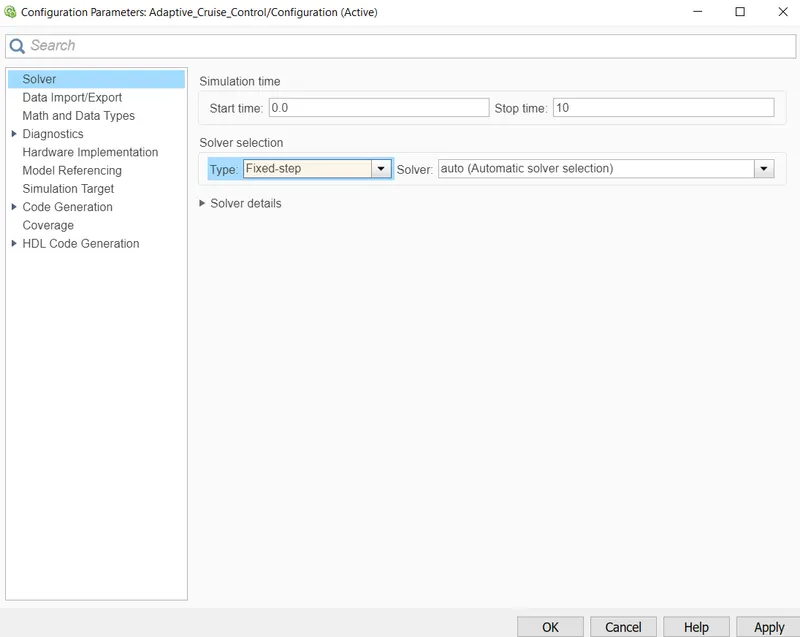
This is the Solver configuration window:
Genareted code type:
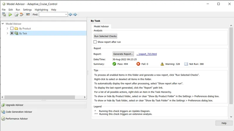
Testing report for code genaretion:
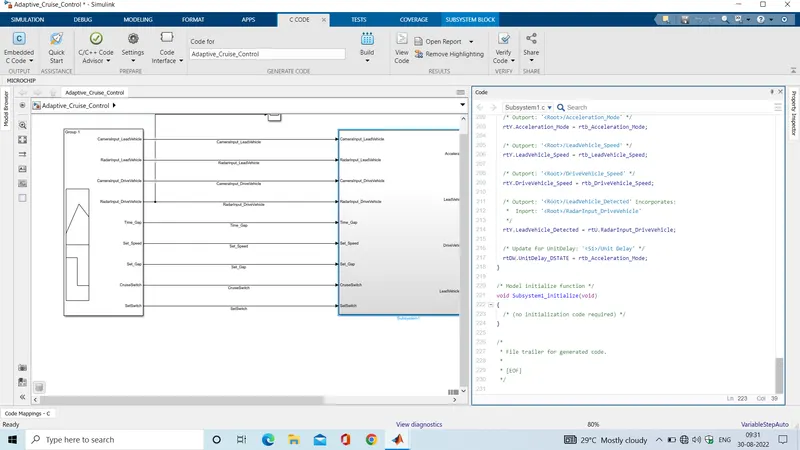
After code genaretion:
/*
 * File: ert_main.c
 *
 * Code generated for Simulink model 'Projectone'.
 *
 * Model version                  : 1.37
 * Simulink Coder version         : 9.5 (R2021a) 14-Nov-2020
 * C/C++ source code generated on : Tue Aug 23 09:50:58 2022
 *
 * Target selection: ert.tlc
 * Embedded hardware selection: Intel->x86-64 (Windows64)
 * Code generation objectives: Unspecified
 * Validation result: Not run
 */

#include
#include               /* This ert_main.c example uses printf/fflush */
#include "Projectone.h"                /* Model's header file */
#include "rtwtypes.h"

/*
 * Associating rt_OneStep with a real-time clock or interrupt service routine
 * is what makes the generated code "real-time".  The function rt_OneStep is
 * always associated with the base rate of the model.  Subrates are managed
 * by the base rate from inside the generated code.  Enabling/disabling
 * interrupts and floating point context switches are target specific.  This
 * example code indicates where these should take place relative to executing
 * the generated code step function.  Overrun behavior should be tailored to
 * your application needs.  This example simply sets an error status in the
 * real-time model and returns from rt_OneStep.
 */
void rt_OneStep(void);
void rt_OneStep(void)
{
  static boolean_T OverrunFlag = false;

  /* Disable interrupts here */

  /* Check for overrun */
  if (OverrunFlag) {
    rtmSetErrorStatus(Projectone_M, "Overrun");
    return;
  }

  OverrunFlag = true;

  /* Save FPU context here (if necessary) */
  /* Re-enable timer or interrupt here */
  /* Set model inputs here */

  /* Step the model for base rate */
  Projectone_step();

  /* Get model outputs here */

  /* Indicate task complete */
  OverrunFlag = false;

  /* Disable interrupts here */
  /* Restore FPU context here (if necessary) */
  /* Enable interrupts here */
}

/*
 * The example "main" function illustrates what is required by your
 * application code to initialize, execute, and terminate the generated code.
 * Attaching rt_OneStep to a real-time clock is target specific.  This example
 * illustrates how you do this relative to initializing the model.
 */
int_T main(int_T argc, const char *argv[])
{
  /* Unused arguments */
  (void)(argc);
  (void)(argv);

  /* Initialize model */
  Projectone_initialize();

  /* Attach rt_OneStep to a timer or interrupt service routine with
   * period 0.2 seconds (the model's base sample time) here.  The
   * call syntax for rt_OneStep is
   *
   *  rt_OneStep();
   */
  printf("Warning: The simulation will run forever. "
         "Generated ERT main won't simulate model step behavior. "
         "To change this behavior select the 'MAT-file logging' option.\n");
  fflush((NULL));
  while (rtmGetErrorStatus(Projectone_M) == (NULL)) {
    /*  Perform other application tasks here */
  }

  /* Disable rt_OneStep() here */

  /* Terminate model */
  Projectone_terminate();
  return 0;
}

/*
 * File trailer for generated code.
 *
 * [EOF]
 */