Project
Objective:
Study the BAJA ATV model using simulink realtime model.
Theory:
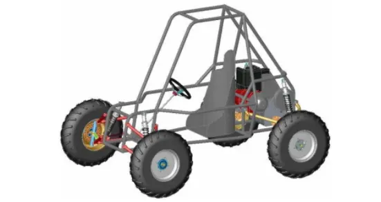
An ATV model basically designed in order to run on various such as soil,Gravel ,peddles etc so due to difficult terrain our main focus is on better ergonomics at same time.
This model is molre powerfull to handle the high torque and speed maintain condition.In the main part for us is CVT for control the torque and speed smooth oparation.
to make better performance with control the cvt ratio wich nothing but a variable gear ratio.
Model Study:
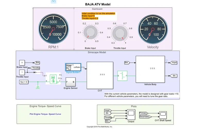
Here the total model ,this model contain a dashboard,a simulink model and a plot section.
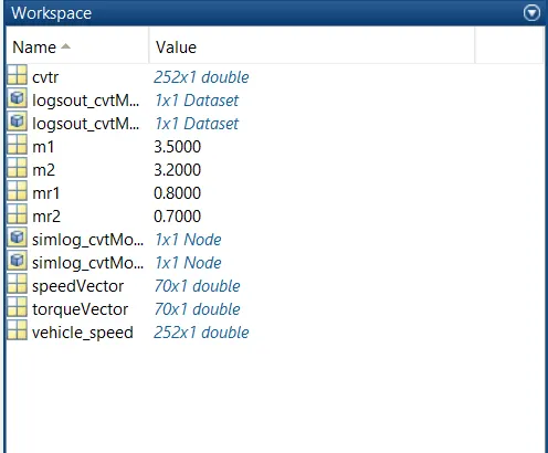
This is the Workspace here the files are loaded which we use for verious conditions for control the CVT ratio.
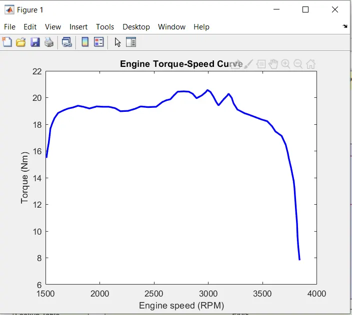
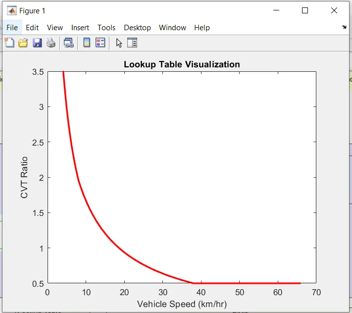
BAJA ATV model torque vs Engineen seed plot Vehicle Speed vs CVT Ratio plot
Dashboard:
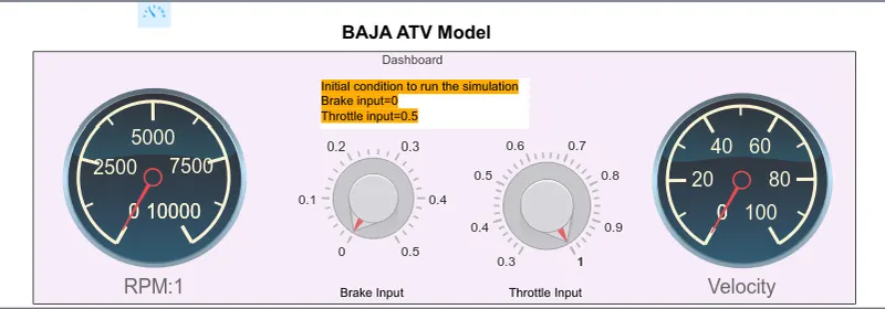
This Dash board contain a RPM meter ,a Velocity meter and two input type pot Breake and Thottle.
This section basically for interface with realistic model mand those components are available in simulink Library Dashboard section.
Here RPM:1 shows the engine RPM and the Velocity meter shose the vehicle speed.
Simscape Model:
This section basically for ATV Model which is represent the real life vaical charectarestics.
[Sensor Block]
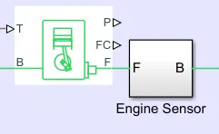
here is a engine model which is actually connected with two inputs like Brake input,Throttle input and simulink mechanical rotational refarance and a Zero block.
The Engine block out put connect with a Engine sensor block which is a simple sensor block which is contain a RPM sensor.
[CVT Block]
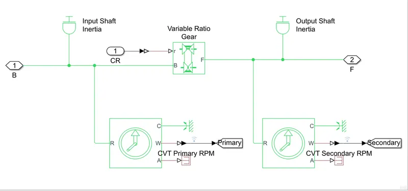
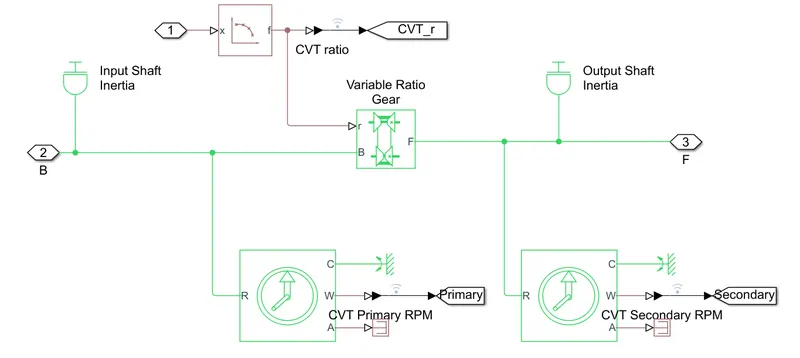
Then the sensor block connected with a CVT model block .which actually contain a variable gear ratio which contain two innertia as input innertia and output innertia and aditional two nos RPM sensor for input and out put speed of Ratio gear.and the variable gear also connected with a gear ratio input block which actually we change for more experiments.sometime we change it as constant value and some time may be signal builder or a lookup table.
after CVT block the system connected with a simple gear.
[Veical Body Block]
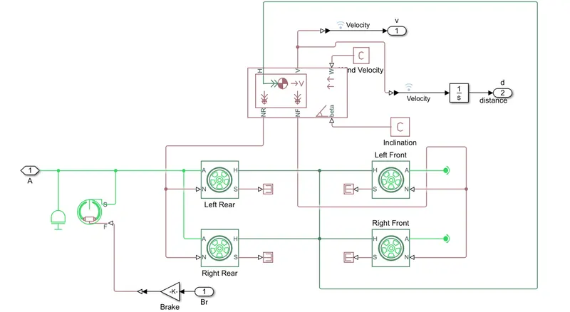
And at last the system connected with a vaical body block which contain the various parameter for real life vaical model smulation.
This mopdel contain four wheeels and other structure block which indicate the body mass friction with air ,plane and so on.
[Vehicle parameters]
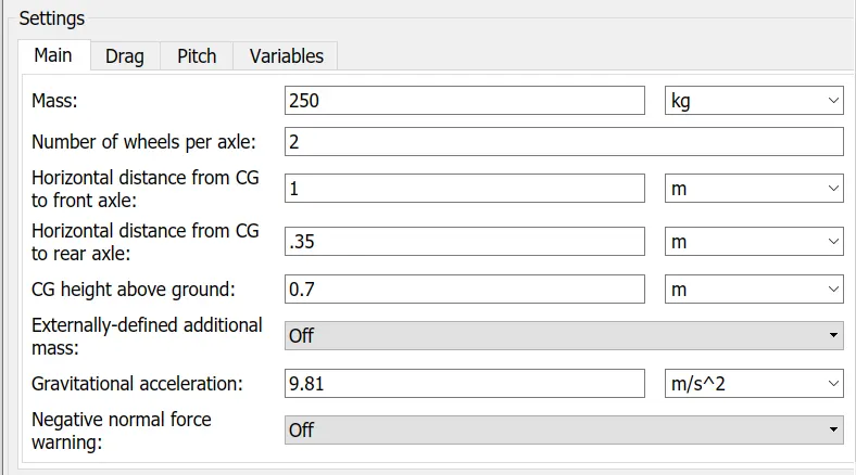
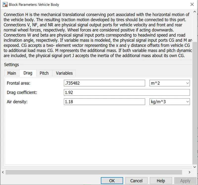
This Parameters are just default values four our model in case of particuler condition we change the parameters as per our requirement.

This is the section where we use various of scope for analysis the result and plod the deta.Here we use for measure the engine input and output shaft speed ,veical speed,Input Brake and input Thrattle data etc.
Case Study:
Case1:
Block Diogram:
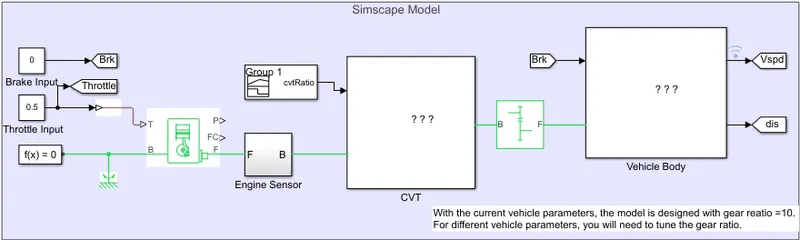
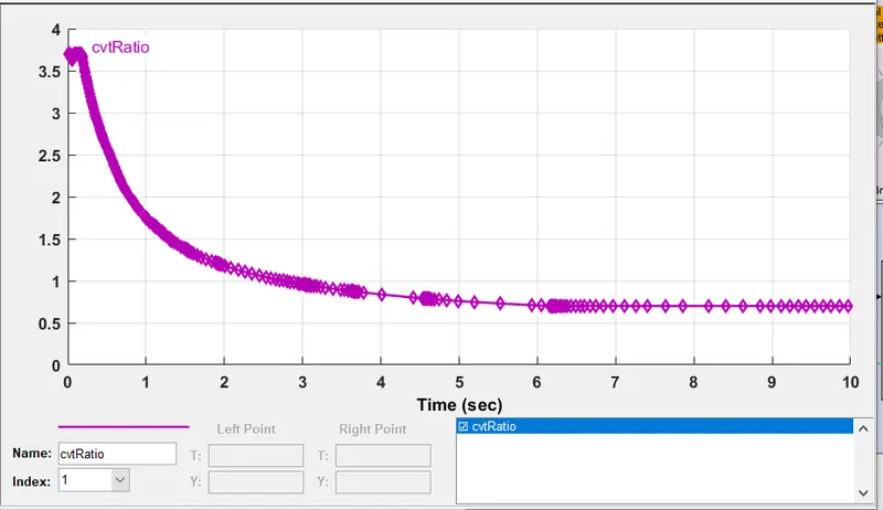
Here we use simple constant block input for brake and Throttle and for CVT ratio we use a signal block for CVT ratio.
Brake value: 0
Throttle value: 0.5
Simulation timeP: 200
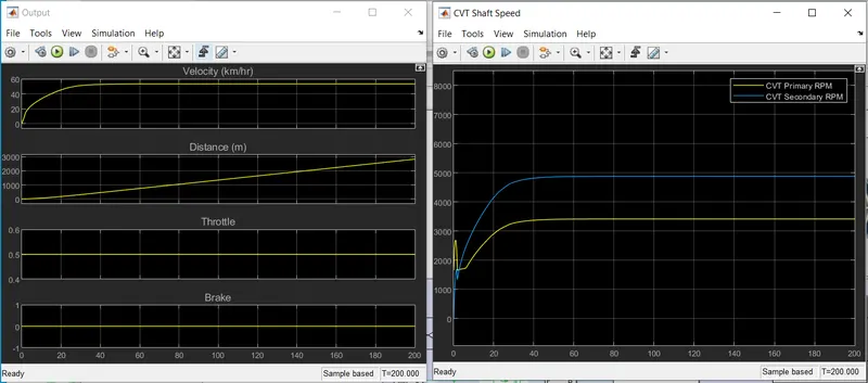
Veical Velocity plot Engine Primary and secondary RPM plot
Input Brake and Throttle plot
2nd case:
Block Diogram:
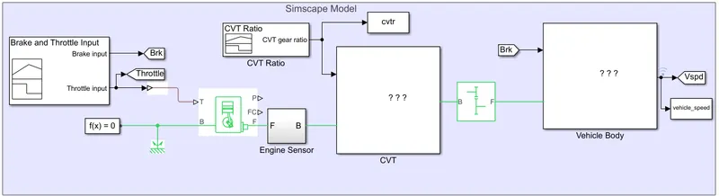
Here we use signal builder as Input section and CVT ratio
Simulation: 200
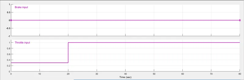
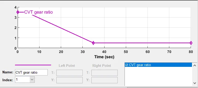
Brake and Thottle input CVT ratio
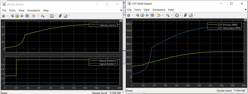
Veical Velocity plot Engine Primary and secondary RPM plot
Input Brake and Throttle plot
3rd case:
Block Diogram:
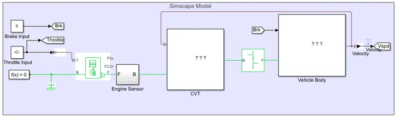
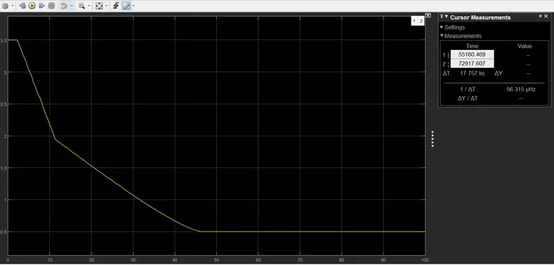
In this case we just use a feedback for control the CVT ratio and we also use the lookup table for give CVT ratio value.
Brake value: 0
Throttle value :0.6
simulation value: 100
Result:
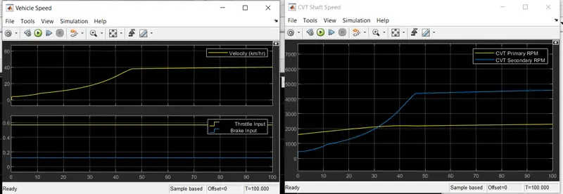
Veical Velocity plot Engine Primary and secondary RPM plot
Input Brake and Throttle plot
CVT Ratio:
\
4th case:
Block Diogram:
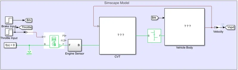
This model is as similar as pevious one ,we just change the input Brake and Throttle as a stape input block.
but as CVT ratio block as similar as previous one.
Simulation Time:200
Result:
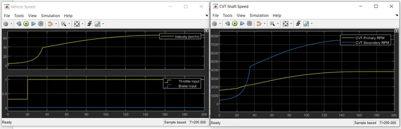
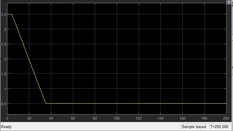
Veical Velocity plot Engine Primary and secondary RPM plot
Input Brake and Throttle plot
CVT Ratio:
Conclusion:
From this model and analysis of all type of conditions we learn tha perfomance of the vehicle body with controling the CVT ratio which we can control verious of way.