Week-6 Challenge: EV Drivetrain
1. Which types of power converter circuits are employed in electric and hybrid electric vehicle?
-----------------------------------------------------------------------------------------------------------------------------------------------------------
ANS:
The power electronics switching type semiconductor base controled circuits are used in electric and hybrid electric vehical.
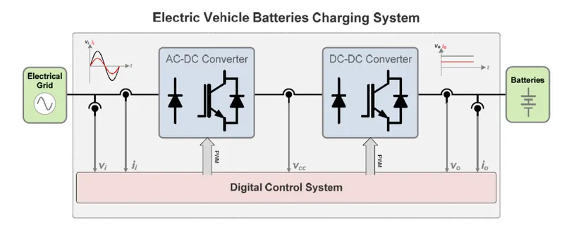
Ther here the AC to DC type converter requare for Charging the battary from charging station and DC to DC converter are requare for oparate the vehical motor and charging the battary at the regenarating braking time.
This type of system use for basically reduce the losses and control more efficiently.If we use regulator type control device then the system genarate the IR losses wich is not economic for industrial basis but replace of regulator type controller to semiconductor base switch controller is more efficient and heat production less.
In this device there is two part one is semiconductor switch and another is control circuit.
At the plase of semiconductor switches we can use thyristors,MOSFET,IGBT,SCR ,GTO etc every type of semiconductor has own charectaristics and we uses those as there aplication base.
for the switching controller we can use programable IC s.
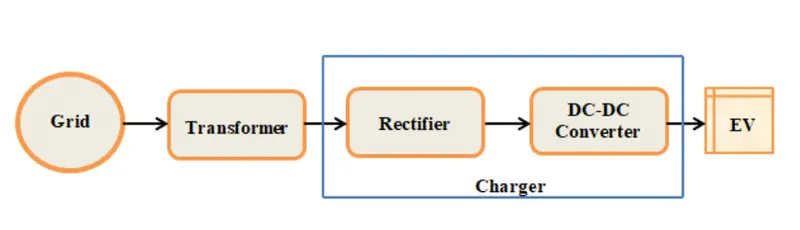
AC to DC converter type :
This converter use for convert the Incoming AC high voltages to DC low voltage battary charging circuit at chargin station-
DC to DC converter for Motor oparated suply:
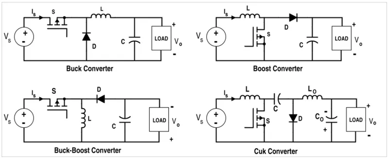
There is four typre of converter is uses for converting the DC to DC power suply.But in case of Electrical vehical we use more stable and suitable circuits.
-------------------------------------------------------------------------------------------------------------------------------------------------------------
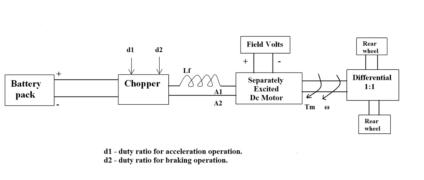
2. An Electric Vehicle's powertrain with 72V battery pack in shown in the diagram below. The duty ratio for acceleration operation is 'd1' and for the braking operation the duty ratio is 'd2'.
The other parameters of the electric vehicle is given below,
Motor and Controller Parameters:
Rated Armature voltage= 72 V
Rated armature current= 400 A
Ra= 0.5Ω, KΦ= 0.7 Volt second
Chopper Switching frequency= 400 Hz
The vehicle speed-torque characteristics are given by the below equation

What is EV steady state speed if duty cycle is 70%?
-------------------------------------------------------------------------------------------------------------------------------------------------------------
ANS:
The given vehical speed torque equation is -
Tv=24.7+(0.0051)*w^2 .................(1)
For the motor torque speed eqation the given parameters are -
Rated Armature voltage= 72 V
Duty cycle=70%=.07
Rated armature current= 400 A
Ra= 0.5Ω,
KΦ= 0.7 Volt second
Chopper Switching frequency= 400 Hz
so the oparating voltage is-
Rated Armature voltage x Dutycycle =72*0.7=50.4 V
Now the Motor torque equation we know -
T=((V*K`phi`)/Ra)-(((K`phi`)^2)*w)/Ra)
Now put the values and calculeting we get-
T=(35.28/0.5)-((0.49*w)/0.5)
T=70.56-0.98*w ........................(2)
Now solving the equation 1 and 2 we get-
T=70.56-0.98*w
Tv=24.7+(0.0051)*w^2
70.56-(0.98*w)=24.7+(0.0051)*w^2
(0.0051)*w^2+(0.98*w)-45.86=0 ..................(3)
solve the equation no 3 we get -
value of x is (38.9150) and (-231.0718)
   %(0.0051)*w^2+(0.98*w)-45.86=0

 a=0.0051;
 b=0.98;
 c=-45.86;
x(1)=(-b+sqrt(b.^2-4.*a.*c))/(2.*a)
x(2)=(-b-sqrt(b.^2-4.*a.*c))/(2.*a)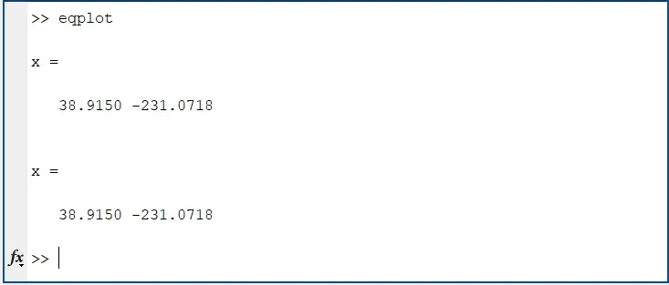
The stedy state speed value is 38.915 red/sec [negative value is neglacting]
-------------------------------------------------------------------------------------------------------------------------------------------------------------
3. Develop a mathematical model of a DC Motor for the below equation using Simulink.
ω">ωω= V/Kϕ">ϕϕ -Ra/Kϕ">ϕϕ^2 .T
-------------------------------------------------------------------------------------------------------------------------------------------------------------
ANS:
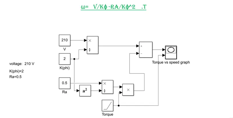
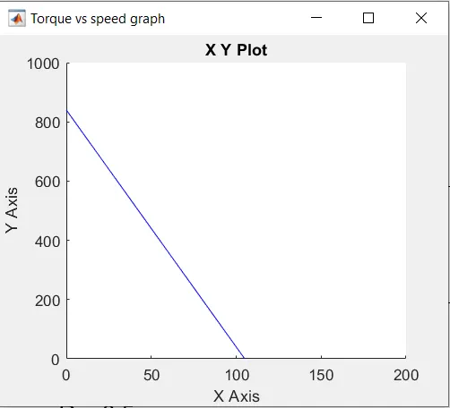
Here Torque at X axis and speed at Y axis.
-------------------------------------------------------------------------------------------------------------------------------------------------------------
4. Refer to the blog on below topic:
Induction Versus DC brushless motors by Wally Rippel, Tesla
Explain in brief about author’s perspective.
-------------------------------------------------------------------------------------------------------------------------------------------------------------
ANS:
According to Wally Rippel there is a revolutionary inventory in electric vehical word is Brush less DC motor and Induction motor.There many advantages and dis advantages are available for two types of motor itself the orther want to compare two types of motors and want to shose more efficient aplicable motor which one.
Induction Motor:
in case of induction motor there is the construction of motor more similar with Brush less DC motor but the diffarance is the rottor is made of thin stack steel laminated with buried peripheral conductors when the three phase current and voltage aply in three stator winding then the produce flux in stator cut in rottor and induce emf genarate a force and the rotter movement start to rotate .Here many things are inportant like at rottor field the induce currant make hysterisis loss and the eddy current loss.also the couse of IR loss the motor genarate the heat.While 3-phase induction motors have great utility, they also have some severe limitations. They cannot operate from DC; AC is a must. Shaft speed is proportionate to line frequency. Hence, when used with utility power, they are constant speed machines. Finally, when operated from utility power, they have limited starting torque and somewhat limited running peak torque capabilities, when compared to DC type machine
Here in case of three phase suply we use a converter because the system runing on battary DC volt and mottor runs with 3ph AC volt.
In case of induction motor the efficency is 85% which is more than a Brush less DC motor.
Brush less DC motor:
In case of Brash less DC motor the rottor portion is the more than two nos of permanent magnet stag which genarate the permanent magnetic field.when the stator variable field genarate the electric field then the motor rottor fell the force and the motor start to rotate.DC brushless rotor, the induction rotor has no magnets – just stacked steel laminations with buried peripheral conductors that form a “shorted structure.” Currents flowing in the stator windings produce a rotating magnetic field that enters the rotor. In turn, the frequency of this magnetic field as “seen” by the rotor is equal to the difference between the applied electrical frequency and the rotational “frequency” of the rotor itself. Accordingly, an induced voltage exists across the shorted structure that is proportionate to this speed difference between the rotor and electrical frequency. In response to this voltage, currents are produced within the rotor conductors that are approximately proportionate to the voltage, hence the speed difference. Finally, these currents interact with the original magnetic field to produce forces – a component of which is the desired rotor torque.
The driver of this motor is produce less heat .
Due to permanent magnet the losses are very less .The Permanent magnet DC motor's effeciency is more than Induction motor.
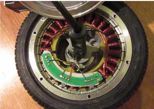
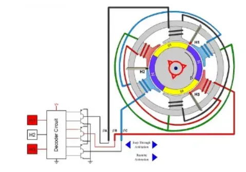
the only disadvantage is the price of the magnate in brash less DC motor .
Conclusiopn:
In case of Electrical vehical motor use ther brassless DC motor is more efficient than the 3ph induction motor.