Project 1 (Mini Project on Vehicle Direction Detection
Mini Project - Vehicle Direction Determination
General Overview:
Identifying the direction of the vehicle is one of the important & diverse features in Autonomous driving & Advanced Driver Assistance Features. This particular sub-feature of identifying the direction of vehicle is basically identifying the direction the vehicle is taking based on the camera input.
Camera reads the road signs & stores into its memory with unique values for left turn, right turn & straight drive. Depending on the direction it is taking, final indication is given to the driver – as an indication if he is driving in the recommended direction or not.
Vehicle Direction Determination can also be coupled along - side features like GPS systems to identify whether the vehicle is reaching its destination in an optimized manner. This sub feature can also be used along with Lane Detection, Highway Warning, Ramp Entry / Exit in Wrong Way Detection etc.
Process:
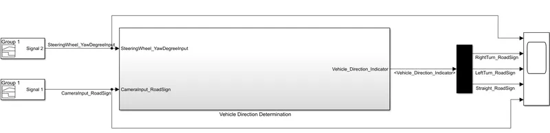
This is the model where we perform the Vehical direction ditermination logick and we make two input signal for make the system reliable input and we can test the system that is the system performing asper our requarement or not.also we take a scop for monitaring the system performance.
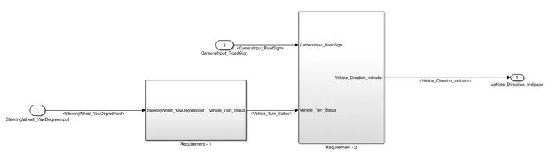
This is the structure for our two reqarement subsystem one is Requarement1 block and another is requarement 2 subsystem here we found that there is twominput signal one CameraInput_RoadSign and another is SteeringWheel_YawDegreeInput and one no output signal is Vehicle_Direction_Indicator which is only the final output and this signal give feedback about to need the vehical direction change or not.
Requirement - 1:
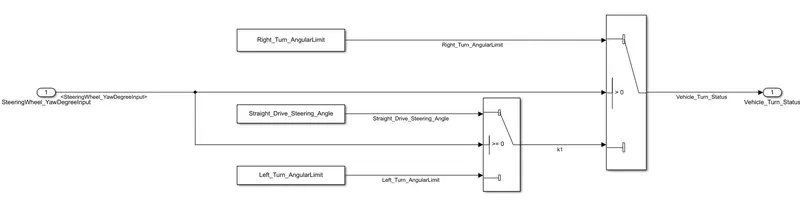
- Steering wheel input as yaw rate (Signal name: SteeringWheel_YawDegreeInput) is the input for this system.
- This is compared against 3 angular values, one each for left turn, right turn & straight drive (Calibration Values: Right_Turn_AngularLimit, Left_Turn_AngularLimit, Straight_Drive_Steering_Angle) to say which specific direction the steering wheel is turning towards.
- Use switch blocks to compare & develop this requirement. Keep this requirement in a subsystem & output of this requirement is a local signal (Signal Name: Vehicle_Turn_Status).
This circuit block is for Requarement1 section here the input signal SteeringWheel_YawDegreeInput come to the logic section and compare with the calibration values and give ultimate result as which signal will come out from the output port Vehicle_Turn_Status.Here we use two comparetor logic if the signal gratter than 0 than the the Right_Turn_AngularLimit this signal will come out,if the signal is equal to zero than Straight_Drive_Steering_Angle and if the signal less than zero than the signal Left_Turn_AngularLimit will come out.
Requirement – 2:
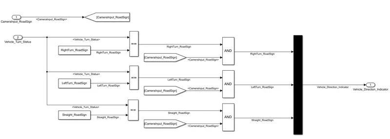
- Keep this requirement as a separate subsystem. Inputs to this requirement are local signal from requirement 1 (Signal Name: Vehicle_Turn_Status) & an input signal from camera (Signal Name: CameraInput_RoadSign), which confirms the occurrence of a road sign.
- Signal Vehicle_Turn_Status is compared against calibration values (Calibration Values: RightTurn_RoadSign, LeftTurn_RoadSign, Straight_RoadSign), if each of them is found equal, then each of the three corresponding output is compared against the camera input signal,
- Using a logical operator block, only one among them is finally given as output signal (Signal Name: Vehicle_Direction_Indicator).
This is the requarement2 subsystem block where the Vehicle_Turn_Status signal came to as input and after cmpare with another calibration parameter the logick convert the signal value to vionary value means which sigan is coming thats condition wise the perticuler signal port give higher value as 1 .After that the output bionary data compare with CameraInput_RoadSign signal and deside to that the need of signal ultimate responce.if camera value low then the system become inactive and when the camera gives higher value then the system become healthy.The ultimately output come out as the form of Vehicle_Direction_Indicator signal form.
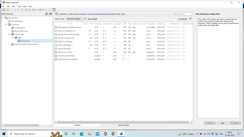
As per our requarement we store the data at the data dictionary database -
Signals & Calibration Data List:
|
Signal / Calibration Name |
Signal Type |
Data Type |
Dimension |
Min |
Max |
Initial Value |
Units |
|
SteeringWheel_YawDegreeInput |
Input |
Int16 |
1 |
-180 |
180 |
- |
Deg |
|
CameraInput_RoadSign |
Input |
Boolean |
1 |
0 |
1 |
- |
- |
|
Vehicle_Turn_Status |
Local |
Int16 |
1 |
-180 |
180 |
- |
Deg |
|
Right_Turn_AngularLimit |
Calibration |
Int16 |
[1 1] |
-180 |
180 |
30 |
Deg |
|
Left_Turn_AngularLimit |
Calibration |
Int16 |
[1 1] |
-180 |
180 |
-120 |
Deg |
|
Straight_Drive_Steering_Angle |
Calibration |
Int16 |
[1 1] |
-180 |
180 |
0 |
Deg |
|
RightTurn_RoadSign |
Calibration |
Int16 |
[1 1] |
-180 |
180 |
30 |
|
|
LeftTurn_RoadSign |
Calibration |
Int16 |
[1 1] |
-180 |
180 |
-120 |
|
|
Straight_RoadSign |
Calibration |
Int16 |
[1 1] |
-180 |
180 |
0 |
|
|
Vehicle_Direction_Indicator |
Output |
Boolean |
1 |
0 |
1 |
- |
- |
And the given picture shose the actual Data dictionary outlook and the data dictionary save DDLS.sldd file which we put as attachment file.
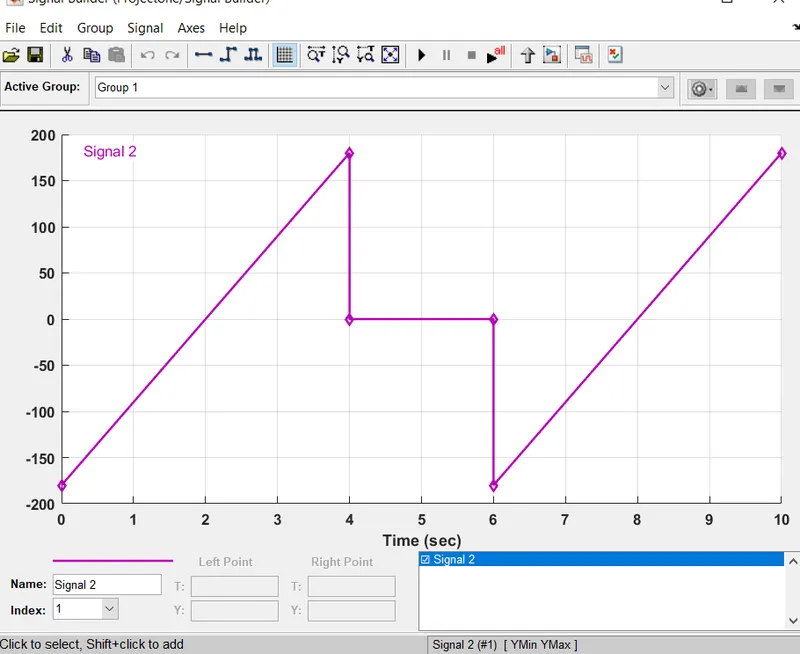
This is the input signal for testing the system where we make ramp signal twise ,one when the camera signal is high and another when camera signal is low and at between two ramp signal there is a constant gero value at same camera signal.
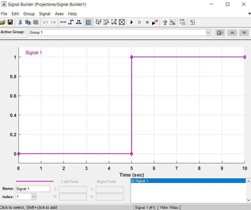
This is the camera signal.Camera on for 5 sec and of for another 5 sec.
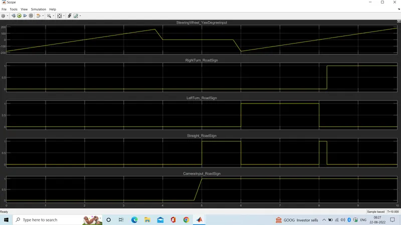
Output responce:
Here the simple model test case where as per our input signa we show that the system respond when the camera signal is high .when the camera signal is low the system is become inactive.here shows the camera signal is high and the input signal is grater than zero then the RightTurn_RoadSign is active. when input signal become zero than the Straight_RoadSign become active and when the input signal become less than zero then the LeftTurn_RoadSign is active.
Coverage Report window:
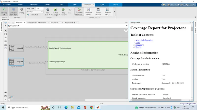
This is the covarage test case report Here after genarate the covarage test case we shows that the block become green colored status that means the system covarage 100% test case without any fault.Covarage test report also attached with the system.
Configuration window:
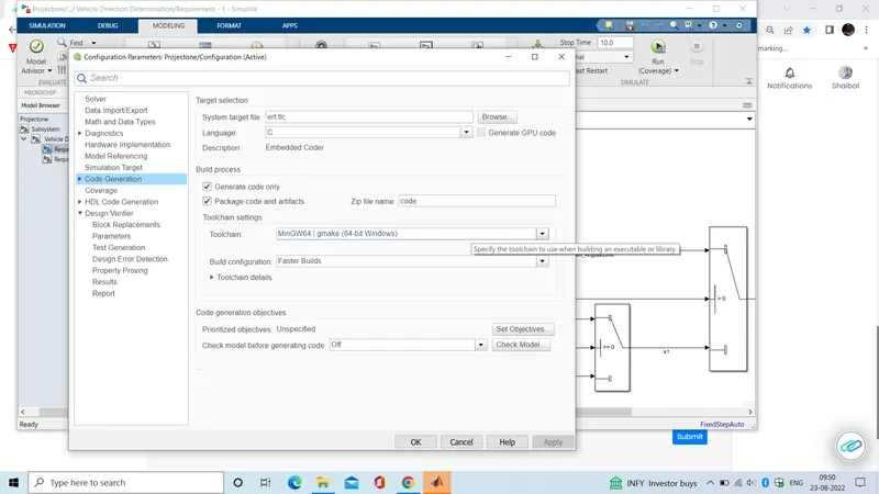
After covarage testing we genarate the code for genareting the embided code we make the conefigare as per our requarement .
Code window:
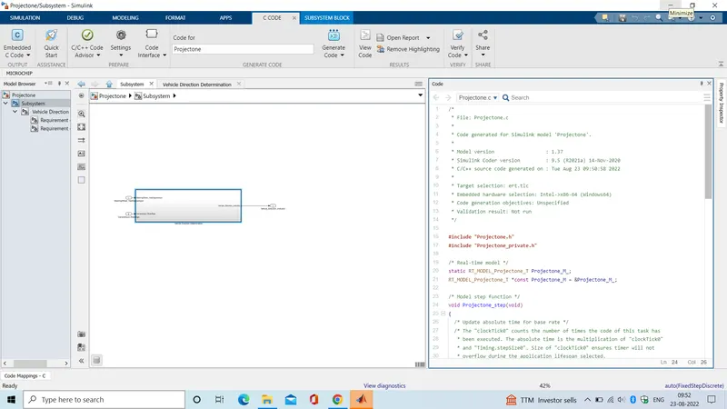
After test we genarate the the embided c code one side there is the total system block and anoder side code display window this show that the code is sucessfully genarate after code genaration process.
Code genareted file:
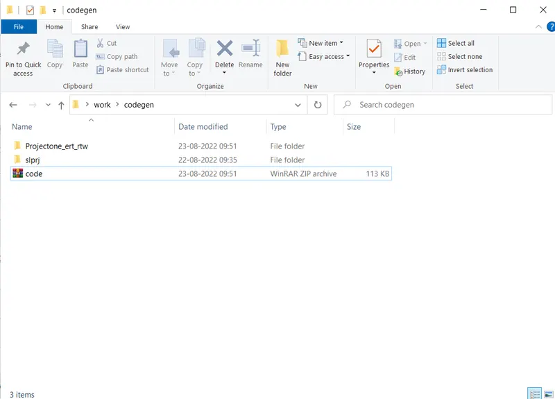
From this picture we shows that the system sucessfully genarate the code file which is actually our targate file.
Genareted Code:
This is our ert_main.c file whis is genarate at out code genarate section.
/*
 * File: ert_main.c
 *
 * Code generated for Simulink model 'Projectone'.
 *
 * Model version                  : 1.37
 * Simulink Coder version         : 9.5 (R2021a) 14-Nov-2020
 * C/C++ source code generated on : Tue Aug 23 09:50:58 2022
 *
 * Target selection: ert.tlc
 * Embedded hardware selection: Intel->x86-64 (Windows64)
 * Code generation objectives: Unspecified
 * Validation result: Not run
 */

#include <stddef.h>
#include <stdio.h>              /* This ert_main.c example uses printf/fflush */
#include "Projectone.h"                /* Model's header file */
#include "rtwtypes.h"

/*
 * Associating rt_OneStep with a real-time clock or interrupt service routine
 * is what makes the generated code "real-time".  The function rt_OneStep is
 * always associated with the base rate of the model.  Subrates are managed
 * by the base rate from inside the generated code.  Enabling/disabling
 * interrupts and floating point context switches are target specific.  This
 * example code indicates where these should take place relative to executing
 * the generated code step function.  Overrun behavior should be tailored to
 * your application needs.  This example simply sets an error status in the
 * real-time model and returns from rt_OneStep.
 */
void rt_OneStep(void);
void rt_OneStep(void)
{
  static boolean_T OverrunFlag = false;

  /* Disable interrupts here */

  /* Check for overrun */
  if (OverrunFlag) {
    rtmSetErrorStatus(Projectone_M, "Overrun");
    return;
  }

  OverrunFlag = true;

  /* Save FPU context here (if necessary) */
  /* Re-enable timer or interrupt here */
  /* Set model inputs here */

  /* Step the model for base rate */
  Projectone_step();

  /* Get model outputs here */

  /* Indicate task complete */
  OverrunFlag = false;

  /* Disable interrupts here */
  /* Restore FPU context here (if necessary) */
  /* Enable interrupts here */
}

/*
 * The example "main" function illustrates what is required by your
 * application code to initialize, execute, and terminate the generated code.
 * Attaching rt_OneStep to a real-time clock is target specific.  This example
 * illustrates how you do this relative to initializing the model.
 */
int_T main(int_T argc, const char *argv[])
{
  /* Unused arguments */
  (void)(argc);
  (void)(argv);

  /* Initialize model */
  Projectone_initialize();

  /* Attach rt_OneStep to a timer or interrupt service routine with
   * period 0.2 seconds (the model's base sample time) here.  The
   * call syntax for rt_OneStep is
   *
   *  rt_OneStep();
   */
  printf("Warning: The simulation will run forever. "
         "Generated ERT main won't simulate model step behavior. "
         "To change this behavior select the 'MAT-file logging' option.\n");
  fflush((NULL));
  while (rtmGetErrorStatus(Projectone_M) == (NULL)) {
    /*  Perform other application tasks here */
  }

  /* Disable rt_OneStep() here */

  /* Terminate model */
  Projectone_terminate();
  return 0;
}

/*
 * File trailer for generated code.
 *
 * [EOF]
 */